

ProductPRODUCT
Featured products



Contact Us
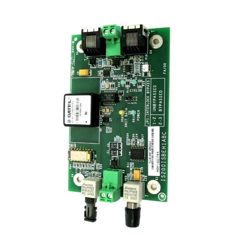
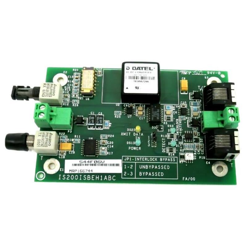
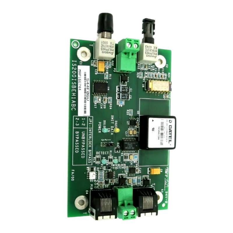
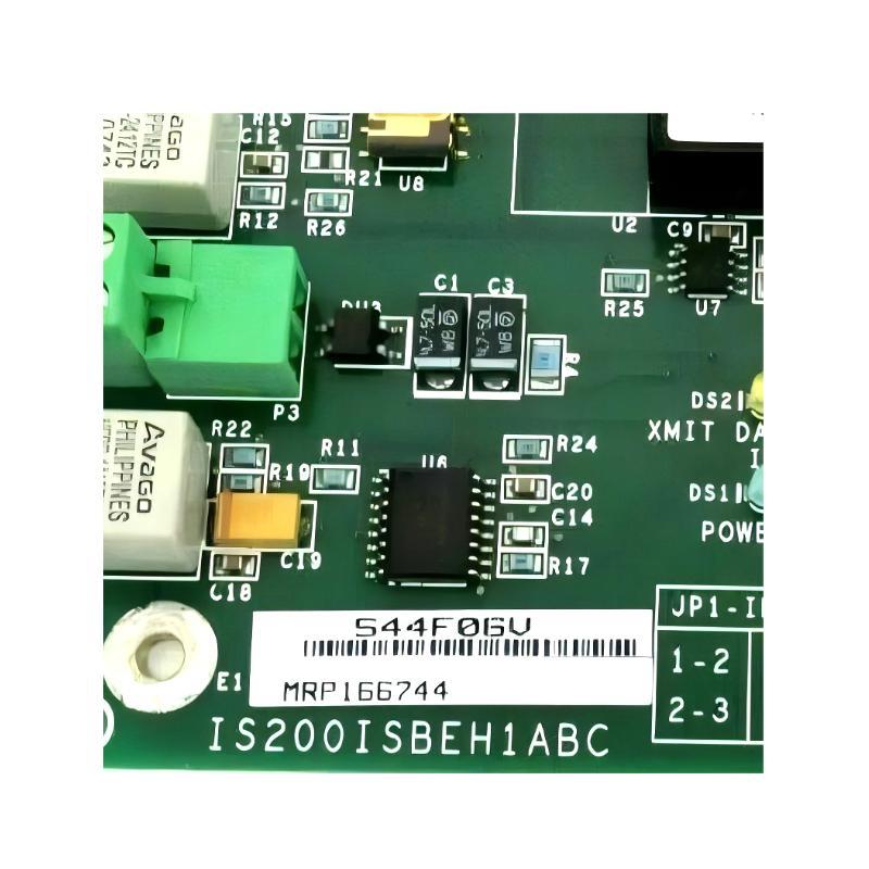
- GE
- IS200ISBEH1ABC
- Synchronous Bus Expansion Board
- USA
- 200 × 120 × 35 mm
- 0.75 kg
- Xiamen, China
- New & In Stock
- T/T, PayPal, Western Union
- 1 Year
- 1-3 Working Days
- DHL, UPS, TNT, FedEx and EMS.
- 24-Hour Service
- COO
- 29
Our advantage

Global Logistics
We have a 10-year logistics and express cooperation agreement, so our products can be shipped to any place in the world.

Brand new and original
Our products are imported in bulk from the place of origin. Because of the cooperative relationship, our products are all original and 100% new.

24-hour service
We provide 7*24 hours service to our customers. We will be there whenever you need us.

Price advantage
All our products are priced very favorably because we have our own warehouse and supply.
| Company Information | |||
| [email protected] | |||
| Mobile | +8615980777398 | ||
| +8615980777398 | |||
| 15980777398 |
Product Overview
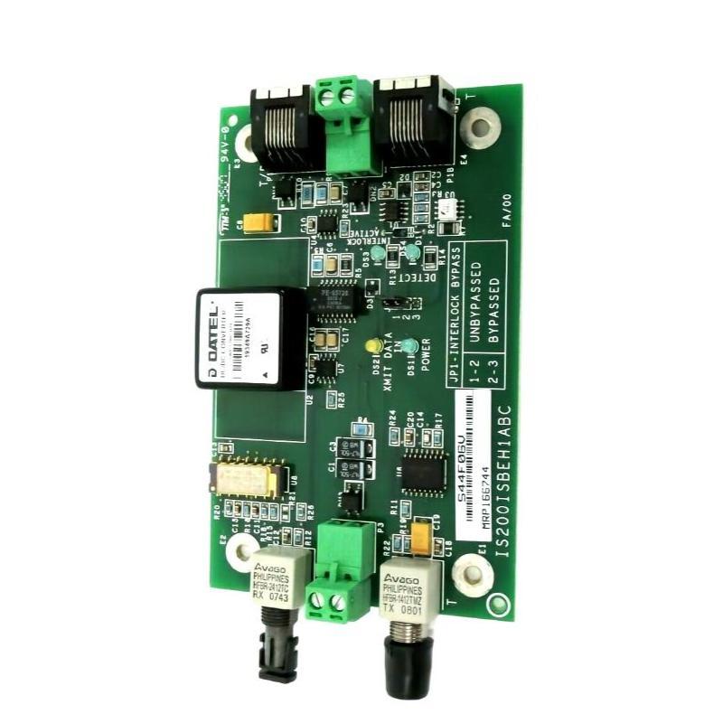
The GE IS200ISBEH1ABC Synchronous Bus Expansion Board is an industrial control-system circuit board designed to support bus expansion and synchronized communication within a larger GE automation architecture. In complex control systems, multiple processors, interface boards, I/O assemblies, and control modules often need to exchange information through an organized communication structure. A bus expansion board provides the necessary hardware interface for extending that communication architecture while maintaining reliable signal transfer between connected system sections.
The GE IS200ISBEH1ABC has a supplied physical size of 200 × 120 × 35 mm and a weight of approximately 0.75 kg. Its board-level construction allows it to be installed within industrial control cabinets or dedicated electronic equipment assemblies where several control and communication components operate together.
The term “synchronous” is particularly relevant in control environments where data or control events need to maintain a predictable relationship with a system timing reference. Reliable bus communication is important because a control system may depend on information being transferred between multiple hardware sections without introducing unexpected delays, interruptions, or communication inconsistencies.
For maintenance and replacement purposes, the complete model number GE IS200ISBEH1ABC should be verified before installation. A board with a similar appearance or physical size should not automatically be considered a suitable substitute because bus architecture, connector assignments, communication functions, and system compatibility can vary between different GE control boards.
Technical Specifications
| Parameter | Specification |
|---|---|
| Manufacturer | GE |
| Model | IS200ISBEH1ABC |
| Product Type | Synchronous Bus Expansion Board |
| Primary Function | Bus expansion and synchronized communication support |
| Application | Industrial control and automation systems |
| Dimensions | 200 × 120 × 35 mm |
| Weight | 0.75 kg |
| Installation | Industrial control cabinet / electronic control assembly |
| Board Type | Communication and bus-interface board |
| System Role | Expansion of the system communication architecture |
| Application Environment | Industrial automation |
| Maintenance | Inspection, communication diagnosis and controlled replacement |
What Is the GE IS200ISBEH1ABC?
The GE IS200ISBEH1ABC is identified as a Synchronous Bus Expansion Board. Its role is associated with extending or interfacing a system bus so that additional control hardware can participate in the overall control architecture.
Industrial automation systems are rarely built around a single circuit board. Instead, they normally contain multiple specialized boards, each responsible for a particular task. Processing boards execute control algorithms, I/O boards handle field signals, communication interfaces transfer information, and supporting boards provide timing, power, or interconnection functions.
The bus provides a pathway through which these different sections can exchange information.
A simplified architecture can be represented as:
Control Processor → System Bus → Expansion Interface → Additional Control Hardware
The IS200ISBEH1ABC fits into this type of system-level architecture by providing bus expansion functionality rather than acting as a standalone PLC or independent controller.
Understanding Synchronous Bus Expansion
A bus expansion system allows a control architecture to connect additional electronic modules without requiring every component to communicate through a completely independent connection.
The basic concept involves three important elements:
Bus Connectivity
The board provides an interface through which signals or data can be transferred between different portions of the control system.
Expansion
Additional system sections can be connected to the broader communication architecture through the expansion function.
Synchronization
Where the system requires coordinated timing, communication events can be associated with an appropriate timing or synchronization structure.
This is especially useful in high-performance industrial control environments where multiple control functions must work together.
Role in an Industrial Control System
The GE IS200ISBEH1ABC should be considered part of a larger control architecture.
A typical system may include:
- Central processing hardware
- Digital and analog I/O
- Communication interfaces
- Timing circuits
- Bus interfaces
- Power supplies
- Terminal assemblies
- Field sensors
- Actuators
- Monitoring equipment
The bus expansion board provides a connection point between appropriate sections of this architecture.
Its reliability therefore contributes to the reliability of the larger communication structure.
A board-level problem may affect multiple downstream devices because loss of bus connectivity can prevent information from reaching other parts of the control system.
Function and Working Principle
The precise internal implementation of the IS200ISBEH1ABC depends on the system in which it is installed. At a functional level, its operation can be understood through the following stages.
1. Bus Signal Reception
The board receives communication or control-related signals from one section of the system bus.
2. Interface Processing
The board manages the electrical interface required to connect the bus with an expanded section of the control architecture.
3. Synchronized Communication
Where applicable, the connected system maintains the required timing relationship between communication events and other control functions.
4. Bus Signal Distribution
The relevant information is made available to the connected expansion section.
5. System-Level Communication
Other control boards or modules can then exchange information through the expanded architecture.
The objective is to provide an organized and reliable communication pathway rather than to perform the complete control algorithm itself.
Why Bus Expansion Is Important
Large industrial automation systems often contain more control functions than can be accommodated by a single local bus section.
A bus expansion architecture provides several practical benefits.
Increased System Capacity
Additional control hardware can be incorporated into the system architecture.
Organized Communication
Multiple boards can exchange information through an established communication structure.
Modular System Design
The control system can be divided into functional sections rather than requiring all electronics to be concentrated in one location.
Easier System Maintenance
A modular communication architecture can make it easier to isolate individual sections during troubleshooting.
Coordinated Control
When synchronized communication is required, the system can maintain predictable relationships between connected control functions.
Industrial Applications
The GE IS200ISBEH1ABC can be relevant to industrial automation environments where GE control hardware uses expandable bus-based architectures.
Turbine Control
Turbine control systems contain numerous electronic control functions and may require coordinated communication between processors, I/O interfaces, monitoring circuits, and other control hardware.
Generator Control
Generator-related automation systems use multiple electronic assemblies to monitor and regulate operating conditions. Bus communication provides an important pathway between these system sections.
Excitation Systems
Excitation control architectures can contain processors, feedback interfaces, gate-drive hardware, and communication components that need to exchange information reliably.
Industrial Drives
Drive systems often contain multiple control and power-interface boards. An organized bus architecture allows these components to operate as a coordinated system.
Process Automation
Complex process-control equipment may require communication between multiple electronic modules distributed across an automation system.
Installation and System Integration
The IS200ISBEH1ABC should be installed by qualified personnel familiar with the relevant GE control architecture.
Because a bus expansion board can influence communication between multiple components, incorrect installation may result in broader system-level problems.
Verify the Exact Model
Confirm the complete part number:
GE IS200ISBEH1ABC
The final revision characters should not be ignored during replacement.
Isolate the Equipment
Place the associated equipment into an appropriate maintenance condition and follow established electrical isolation procedures.
Document Existing Connections
Before removing an installed board, document cable and connector locations. This is especially important when multiple communication connections have similar physical characteristics.
Inspect the Replacement
Check the replacement board for:
- Physical damage
- Bent connectors
- Cracked PCB material
- Corrosion
- Contamination
- Signs of overheating
- Damaged mounting hardware
Install the Board
Install the board into its designated position without applying excessive mechanical force.
Reconnect Communication Paths
Verify that every connector is correctly seated and that cables are routed according to the existing system configuration.
Commissioning After Installation
After physical installation, the system should be returned to service in a controlled manner.
Recommended verification steps include:
- Confirm board installation.
- Verify connectors.
- Check relevant power conditions.
- Start the control system according to the approved procedure.
- Review system diagnostics.
- Check bus communication status.
- Verify communication with connected modules.
- Monitor the system for abnormal alarms.
- Confirm normal operation under appropriate operating conditions.
A successful power-up does not necessarily prove that the bus expansion function is working correctly. Communication should be verified at the system level.
Troubleshooting the GE IS200ISBEH1ABC
When a bus communication problem occurs, technicians should consider the complete communication path.
A useful diagnostic sequence is:
Power → Board → Connector → Bus → Expansion Section → Connected Module → Control Application
This prevents unnecessary replacement of the IS200ISBEH1ABC when the actual fault is located elsewhere.
Loss of Bus Communication
Possible causes include:
- Loose connector
- Incorrect installation
- Damaged communication cable
- Power-supply problem
- Faulty connected module
- Bus interface problem
- Board-level failure
- System configuration issue
Intermittent Communication
Intermittent communication is often more difficult to diagnose than a complete failure.
Possible causes include:
- Vibration
- Connector movement
- Thermal cycling
- Aging components
- Electrical noise
- Cable damage
- Poor shielding or grounding
If communication becomes unstable only after the equipment warms up, thermal behavior should be investigated.
Multiple Modules Report Communication Errors
If several connected devices report communication problems simultaneously, technicians should first investigate the shared communication path.
For example:
Common Power Supply → Bus Interface → Expansion Board → Communication Network
A common-point failure can affect several downstream devices at once.
Diagnosing Bus-Related Faults
A structured diagnostic method can significantly reduce repair time.
Step 1: Identify the Scope of the Fault
Determine whether one module or several modules are affected.
A single-device fault may point toward a local connection, while multiple-device faults may indicate a shared bus or power problem.
Step 2: Review System Diagnostics
Record communication alarms and diagnostic messages before resetting the system.
Step 3: Inspect Physical Connections
Check connectors, cables, and mounting hardware.
Step 4: Verify Power
Confirm that the board and associated communication hardware receive the expected electrical supply.
Step 5: Check the Bus Path
Trace the communication route from the primary control section through the expansion interface to the affected module.
Step 6: Compare With a Known-Good Condition
Where system procedures permit, compare the affected communication path with a functioning path.
Step 7: Evaluate the Board
Only after external causes have been reasonably eliminated should the IS200ISBEH1ABC itself be considered the primary suspect.
Common Failure Causes
Connector Problems
Poor electrical contact can interrupt communication even when the board itself is operating correctly.
Cable Damage
Industrial cables can be affected by vibration, bending, heat, abrasion, or improper routing.
Electrical Noise
Power equipment and switching devices can generate electromagnetic interference that affects sensitive communication signals.
Thermal Stress
Repeated heating and cooling can contribute to aging of electronic components and soldered connections.
Vibration
Continuous industrial vibration can gradually affect connectors and mechanical mounting.
Contamination
Dust and conductive particles can contribute to insulation or contact problems.
Component Aging
Long-term operation can eventually affect electronic components and reduce system reliability.
Preventive Maintenance
Preventive maintenance should cover both the IS200ISBEH1ABC and the surrounding communication architecture.
Recommended activities include:
- Inspect connectors periodically.
- Check cable routing and mechanical support.
- Keep control cabinets clean.
- Maintain appropriate ventilation.
- Monitor cabinet temperature.
- Review communication diagnostics.
- Record recurring communication alarms.
- Check for signs of corrosion.
- Inspect mounting hardware.
- Maintain suitable ESD procedures.
- Keep an appropriately identified spare available for critical equipment.
Preventive maintenance is particularly useful for legacy systems where replacement hardware may require longer procurement or testing.
Replacement Considerations
The supplied physical specifications for the GE IS200ISBEH1ABC are:
Dimensions: 200 × 120 × 35 mm
Weight: 0.75 kg
These specifications are useful for inventory management, mechanical planning, shipping, and storage.
However, physical compatibility does not establish electrical or functional compatibility.
Before installing a replacement, maintenance personnel should verify:
- Complete part number
- Board revision
- Connector arrangement
- Communication architecture
- Installation position
- Associated control hardware
- Cable configuration
- System configuration
A board with similar dimensions may perform a completely different communication or control function.
Spare-Part Management
For critical industrial automation equipment, spare-part management should include detailed identification records.
A recommended record for the IS200ISBEH1ABC includes:
| Parameter | Information |
|---|---|
| Manufacturer | GE |
| Model | IS200ISBEH1ABC |
| Product Type | Synchronous Bus Expansion Board |
| Dimensions | 200 × 120 × 35 mm |
| Weight | 0.75 kg |
| Application | Industrial control and automation |
| Storage | Clean, dry, ESD-protected environment |
| Installation Location | Record cabinet/rack position |
| Condition | New / tested / installed / removed |
| Maintenance History | Record fault and replacement information |
Accurate inventory records help technicians quickly locate the correct component during an unexpected communication failure.
Handling and Storage
The IS200ISBEH1ABC should be treated as a sensitive industrial electronic component.
Recommended handling practices include:
- Use appropriate ESD protection.
- Avoid touching conductive contacts unnecessarily.
- Protect connectors from impact.
- Handle the board carefully.
- Store it in protective packaging.
- Keep it away from moisture.
- Avoid conductive dust and contaminants.
- Maintain clear model identification.
The supplied weight of 0.75 kg should also be considered when packaging and transporting the board to prevent mechanical impact.
Relationship With Other Control Components
A bus expansion board normally depends on the surrounding control architecture.
Its operation can be affected by:
- Main processing hardware
- Communication interfaces
- Power supplies
- Backplanes
- Connectors
- Communication cables
- Expansion modules
- System configuration
This means that troubleshooting should not isolate the board from the rest of the system.
For example, a communication failure could originate from an upstream processor, while the IS200ISBEH1ABC may simply be reporting or passing through the resulting abnormal condition.
System-level analysis is therefore more effective than replacing boards based solely on alarm descriptions.
Synchronous Communication and Control Reliability
Synchronization is important when multiple control functions must work together.
Consider a simplified sequence:
Control Event → Bus Communication → Data Reception → Control Decision → Output Response
If communication timing becomes unpredictable, the downstream control logic may receive information at an unexpected point in its operating cycle.
The consequences depend on the particular application, but potential symptoms can include:
- Communication alarms
- Delayed status updates
- Inconsistent feedback
- Unexpected control responses
- Intermittent system faults
Maintaining a reliable bus architecture therefore contributes to the stability of the overall automation system.
Long-Term Maintenance Strategy
For legacy GE control installations, long-term reliability depends on more than replacing failed boards.
A practical strategy includes:
- Maintain accurate part-number records.
- Keep critical communication boards available as spares.
- Monitor communication diagnostics.
- Inspect connectors and cables regularly.
- Control cabinet temperature and cleanliness.
- Record every board replacement.
- Analyze recurring failures.
- Test replacement hardware before critical installation where practical.
- Verify compatibility before substitution.
This approach can reduce unplanned downtime and make troubleshooting more systematic.
Key Advantages
Bus Expansion Capability
The IS200ISBEH1ABC provides an interface for expanding the communication architecture of a larger industrial control system.
Synchronized Communication Support
Its synchronous bus function supports coordinated communication within the applicable control architecture.
Modular System Integration
The board allows different sections of an industrial automation system to be connected through a structured bus arrangement.
Compact Construction
The supplied 200 × 120 × 35 mm dimensions make it suitable for integration into industrial electronic equipment.
Manageable Weight
At 0.75 kg, the board can be handled and stocked relatively easily as a replacement component.
Useful for Legacy-System Maintenance
A correctly identified spare can help support the continued operation of established GE automation equipment.
Technical FAQs
What is the GE IS200ISBEH1ABC?
The GE IS200ISBEH1ABC is a Synchronous Bus Expansion Board associated with bus expansion and synchronized communication within an industrial control architecture.
What are the dimensions of the IS200ISBEH1ABC?
The supplied dimensions are 200 × 120 × 35 mm.
How much does the IS200ISBEH1ABC weigh?
The supplied weight is 0.75 kg.
What is the purpose of a synchronous bus expansion board?
It provides a hardware interface for extending a control-system bus and supporting communication between different sections of the automation architecture.
Is the IS200ISBEH1ABC a standalone PLC?
No. It is a specialized communication and bus-interface board that operates within a larger industrial control system.
What can cause communication problems?
Possible causes include connector faults, cable damage, power problems, electrical interference, vibration, thermal stress, configuration issues, connected-module failures, or board-level faults.
Can another IS200 board replace the IS200ISBEH1ABC?
Not automatically. The complete part number, revision, connector configuration, communication architecture, and system compatibility should be verified before substitution.
How should the board be stored?
It should be stored in a clean, dry, ESD-protected environment and protected from impact, moisture, contamination, and excessive environmental conditions.
Conclusion
The GE IS200ISBEH1ABC Synchronous Bus Expansion Board is a specialized industrial automation component designed to support bus expansion and synchronized communication within a larger GE control architecture. By providing an organized communication interface between system sections, it can contribute to reliable information exchange and coordinated operation among multiple control components.
The supplied dimensions are 200 × 120 × 35 mm, with a weight of 0.75 kg. These specifications are useful for installation planning, spare-part management, transportation, and storage.
When communication problems occur, technicians should evaluate the entire bus path rather than immediately assuming that the IS200ISBEH1ABC has failed. Power, connectors, cables, connected modules, electromagnetic interference, environmental conditions, and system configuration can all influence communication performance.
For replacement applications, the complete GE IS200ISBEH1ABC model designation should be carefully verified. Correct identification, controlled installation, preventive maintenance, and systematic troubleshooting can help maintain the reliability of GE industrial automation and control systems.