

ProductPRODUCT
Featured products
Contact Us
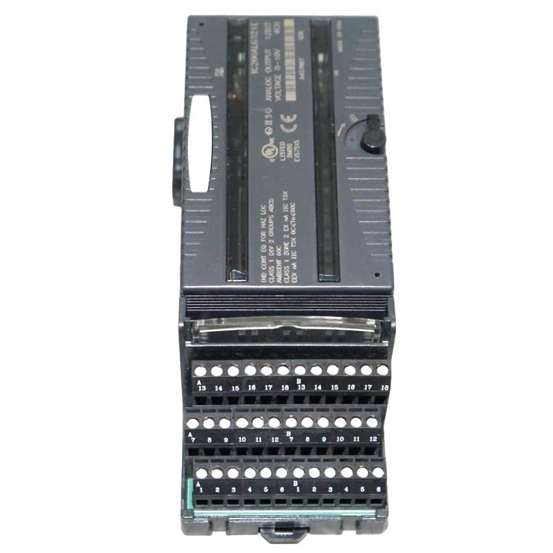
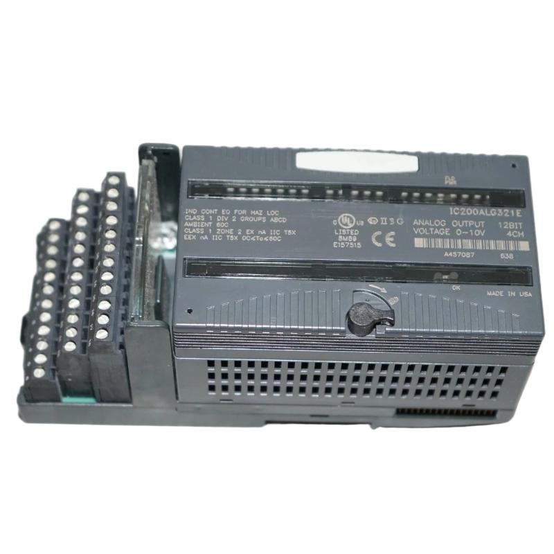
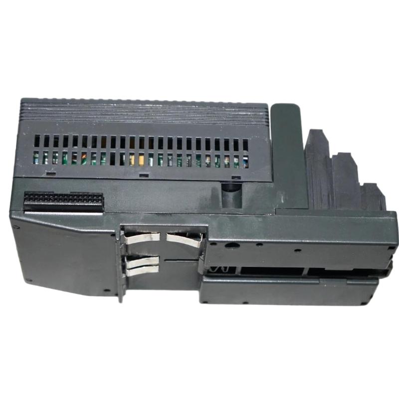
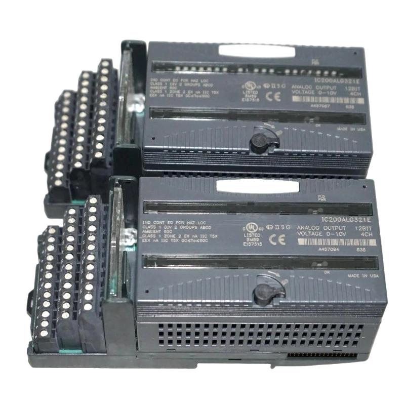
- GE
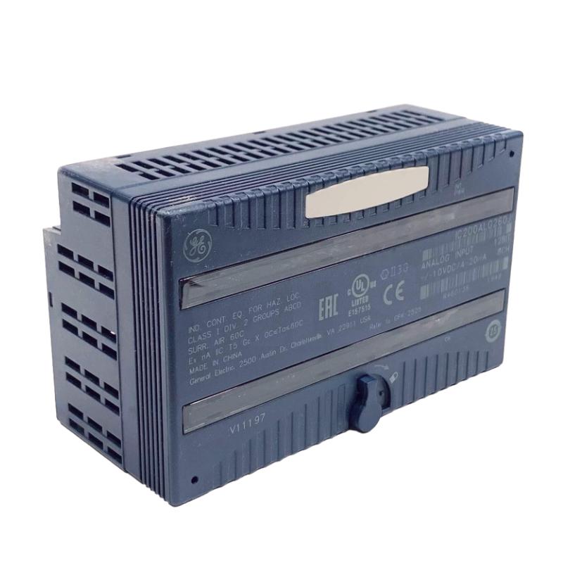
- IC200ALG321B
- Analog Output Module
- USA
- 110 × 66.8 × 50 mm
- 0.136 kg
- Xiamen, China
- New & In Stock
- T/T, PayPal, Western Union
- 1 Year
- 1-3 Working Days
- DHL, UPS, TNT, FedEx and EMS.
- 24-Hour Service
- COO
- 42
Our advantage

Global Logistics
We have a 10-year logistics and express cooperation agreement, so our products can be shipped to any place in the world.

Brand new and original
Our products are imported in bulk from the place of origin. Because of the cooperative relationship, our products are all original and 100% new.

24-hour service
We provide 7*24 hours service to our customers. We will be there whenever you need us.

Price advantage
All our products are priced very favorably because we have our own warehouse and supply.
| Company Information | |||
| [email protected] | |||
| Mobile | +8615980777398 | ||
| +8615980777398 | |||
| 15980777398 |
Product Overview
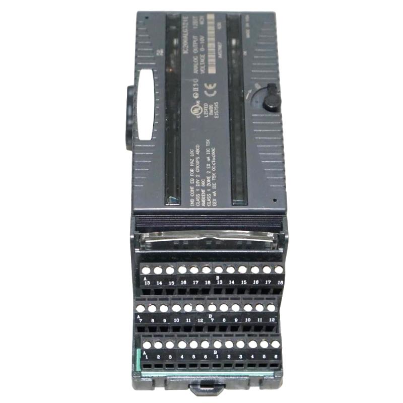
The GE IC200ALG321B VersaMax 4-Channel Analog Output Module converts digital output commands from a VersaMax controller or Network Interface Unit into four analog voltage signals for field equipment. It is intended for applications where control devices require a continuously variable 0–10 VDC command rather than a simple ON/OFF signal.
Typical loads include valve positioners, proportional actuators, analog control interfaces, and equipment that accepts voltage-based speed or position references. Each of the four channels operates as a single-ended analog voltage output, allowing several independent control signals to be handled from one module.
The module operates through a compatible VersaMax I/O carrier, which provides the physical connection to the backplane and field wiring. An external field-side power supply is required for the analog output circuits, while the PLC or Network Interface Unit supplies the output data through the backplane.
The module also supports configurable output behavior when communication or backplane power is interrupted. Depending on the carrier jumper configuration, outputs can either retain their last commanded value or return to 0 V, making the setting an important consideration when the connected equipment has a defined safe-state requirement.
Technical Specifications
| Parameter | Specification |
|---|---|
| Product Type | Analog Output Module |
| Product Series | VersaMax |
| Model | IC200ALG321B |
| Number of Analog Outputs | 4 |
| Output Type | Analog Voltage |
| Output Range | 0 to 10 VDC |
| Resolution | 12 Bit |
| Output Configuration | 4 Single-Ended Outputs |
| Update Rate | 0.3 ms maximum |
| External Power Supply | 18–30 VDC recommended range |
| Application | Analog Equipment and Process Control |
| Dimensions | 110 × 66.8 × 50 mm |
| Weight | 0.136 kg |
Product Features
- Four analog voltage output channels for independent control signals.
- Provides a 0–10 VDC output range for compatible analog devices.
- Uses 12-bit digital-to-analog conversion.
- Maximum module update rate of approximately 0.3 ms.
- Requires an external field-side power supply for the analog output circuits.
- Provides single-ended output channels for connection to compatible loads.
- Integrates with VersaMax carriers and controller or Network Interface Unit architectures.
- Supports configurable output behavior during loss of backplane power or communication.
- Includes field-power and backplane-status indication through the module LEDs.
Working Principle
The IC200ALG321B receives four words of analog output data from the VersaMax CPU or Network Interface Unit and converts the digital values into corresponding voltage signals.
VersaMax CPU / NIU → IC200ALG321B → 0–10 VDC Output → Analog Actuator / Control Device
The output process works as follows:
- The PLC application calculates the required analog command.
- The controller sends the corresponding digital output data through the VersaMax backplane.
- The IC200ALG321B processes one output data word for each channel.
- The module converts the digital values into analog voltage levels.
- Each output channel supplies a corresponding 0–10 VDC signal to the connected field device.
- The receiving device uses the voltage level as a proportional command for position, speed, flow, pressure, or another controlled variable.
The module’s output resolution corresponds to approximately 2.5 mV per 8 counts, while the application program determines the scaling between the engineering value and the voltage command.
Role in a VersaMax Control Architecture
The IC200ALG321B operates at the analog output layer of a VersaMax control architecture, translating controller calculations into proportional electrical commands for field equipment.
VersaMax Controller / NIU → VersaMax Carrier → IC200ALG321B → 0–10 VDC Device → Controlled Equipment
| System Element | Typical Function |
|---|---|
| VersaMax CPU | Executes application logic and calculates analog commands |
| Network Interface Unit | Provides controller/network communication in distributed I/O configurations |
| VersaMax Carrier | Provides the module’s physical and electrical interface |
| IC200ALG321B | Converts digital output data into four analog voltage signals |
| External 24 VDC Supply | Supplies field-side power for the output circuits |
| Valve Positioner | Uses the analog voltage to control valve position |
| Variable-Speed Interface | Uses voltage reference for proportional equipment control |
| Analog Actuator | Converts the voltage command into mechanical action |
| HMI | Displays commanded and actual operating values |
| Field Wiring | Carries the analog voltage signals to connected devices |
Industrial Applications
| Application | Typical Use |
|---|---|
| Process Automation | Sending proportional commands to valves and actuators |
| Water Treatment | Controlling valve position, dosing equipment, and variable process devices |
| HVAC Systems | Providing voltage references for compatible fan and damper control equipment |
| Manufacturing | Analog positioning and speed-reference control |
| Packaging Machinery | Controlling proportional actuators and machine-positioning devices |
| Pump Systems | Providing variable control references to compatible equipment |
| Material Handling | Analog speed or position commands for machine components |
| Utility Systems | Generating voltage-based control signals for field equipment |
| Legacy VersaMax Installations | Replacement of existing 4-channel analog output modules |
Installation and Maintenance
- Verify that the IC200ALG321B is compatible with the selected VersaMax carrier.
- Confirm that the controlled device accepts a 0–10 VDC analog command.
- Provide the required external field-side power supply for the output circuits.
- Install the module securely on the carrier and ensure that the connectors are fully engaged.
- Check the wiring of each output channel and its corresponding return connection.
- Use suitable shielded twisted-pair wiring for analog signals where required by the installation environment.
- Keep analog output cables away from high-current motor and switching circuits to reduce electrical interference.
- Confirm that the field device’s input impedance is suitable for the module output.
- Configure the PLC output data and scaling so that the digital command corresponds correctly to the required voltage.
- Verify the FLD PWR and OK indicators during startup.
- Check the output voltage with suitable test equipment when commissioning each channel.
- Confirm whether the carrier jumper is configured for Hold Last State or default-to-0 V behavior.
- If one channel produces an incorrect voltage, inspect its wiring, load, configuration, and channel assignment before replacing the module.
- If all four channels are affected, check field power, backplane power, carrier connections, controller communication, and module status.
- During preventive maintenance, inspect terminal connections, cable shielding, carrier contacts, and field-device interfaces.
An incorrect analog output can originate from PLC scaling, field power, wiring, load impedance, carrier connections, or the receiving device. Measuring the actual voltage at the module terminals and then at the field device is a useful way to separate an I/O problem from a downstream wiring or equipment issue.
Related Components
| Component | Function |
|---|---|
| VersaMax CPU | Generates analog output commands |
| VersaMax Network Interface Unit | Provides distributed I/O communication |
| VersaMax I/O Carrier | Provides the physical module and backplane connection |
| 24 VDC Field Power Supply | Supplies power for the analog output circuits |
| Analog Valve Positioner | Uses the 0–10 VDC signal for proportional valve control |
| Analog Actuator | Responds to the variable voltage command |
| Variable-Speed Equipment Interface | Accepts an analog voltage reference |
| Shielded Twisted-Pair Cable | Carries low-level analog output signals |
| Terminal Assembly | Provides field wiring connections |
| HMI / SCADA | Displays command values and operating conditions |
Recommended Related Models
| Model / Series | Product Type | Typical Application |
|---|---|---|
| IC200ALG321B | VersaMax Analog Output Module | 4-channel 0–10 VDC analog output |
| IC200ALG320 | VersaMax Analog Output Module | 4-channel 4–20 mA analog output |
| IC200ALG322 | VersaMax Analog Output Module | 4-channel ±10 VDC analog output |
| IC200ALG325 | VersaMax Analog Output Module | 8-channel voltage output applications |
| IC200ALG326 | VersaMax Analog Output Module | 8-channel current output applications |
| IC200ALG327 | VersaMax Analog Output Module | 12-channel voltage output applications |
| IC200ALG328 | VersaMax Analog Output Module | 12-channel current output applications |
| IC200ALG331 | VersaMax Analog Output Module | Isolated voltage/current output applications |
| VersaMax I/O Series | Modular I/O Platform | Distributed machine and process control |
Key Advantages
- Four independent analog voltage outputs provide proportional control for compatible field devices.
- 0–10 VDC range covers common analog command interfaces.
- 12-bit resolution supports reasonably fine output adjustment for process and machine control.
- Fast output update capability is suitable for applications requiring frequent command updates.
- External field power separates the output circuit supply from the controller’s logic operation.
- Configurable loss-of-communication behavior allows the application to select between holding the last command and returning to 0 V.
- Fits the modular VersaMax I/O architecture and can be used in both centralized and distributed control arrangements.
Technical FAQs
What type of equipment can use the IC200ALG321B output?
The module can drive compatible devices that accept a 0–10 VDC analog input, including valve positioners, proportional actuators, analog speed references, dampers, and other control interfaces. The receiving device’s input impedance and electrical requirements should be checked before connection.
Does the IC200ALG321B require an external power supply?
Yes. The analog output circuits require external field-side power. The recommended external supply range is 18–30 VDC, and the field supply must remain available for the outputs to operate correctly.
What happens to the outputs if the PLC or backplane communication is interrupted?
The output behavior can be configured through the carrier jumper. The outputs can either hold their last commanded state or be configured to default to 0 V when backplane power or communication is interrupted.
How can an incorrect 0–10 V output be diagnosed?
Measure the voltage directly at the module’s output terminals first. If the voltage is correct at the module but incorrect at the field device, inspect the cable, return connection, shielding, and receiving device. If the module voltage itself is incorrect, check PLC scaling, output data, field power, carrier connections, and the affected channel.