

ProductPRODUCT
Featured products
Contact Us
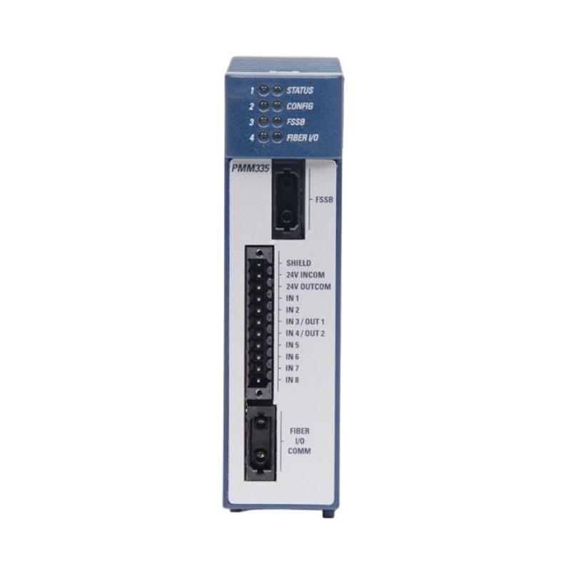
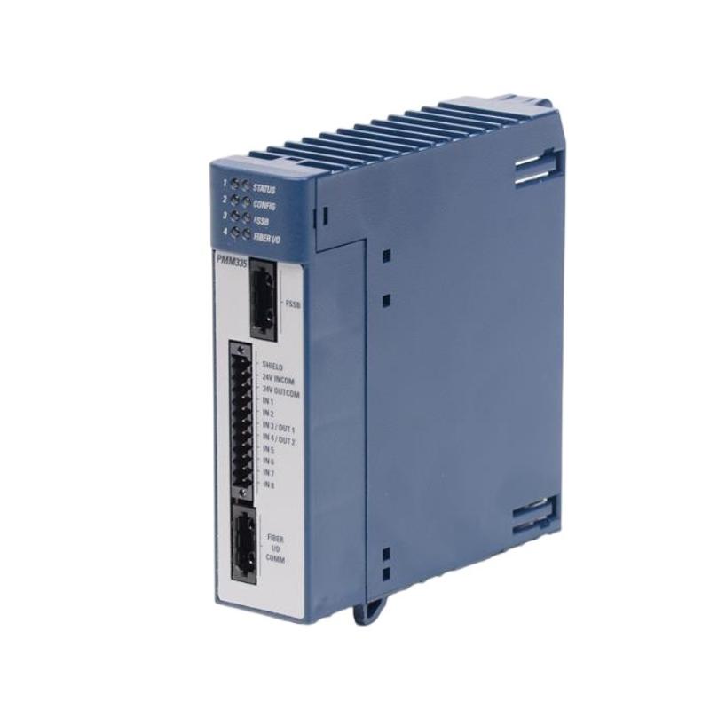
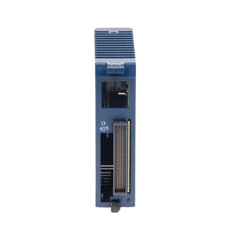
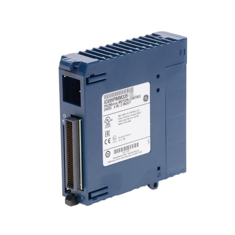
- GE
- IC695PMM335
- Multi-Axis Motion Controller Module
- USA
- 185 × 120 × 45 mm
- 0.7 kg
- Xiamen, China
- New & In Stock
- T/T, PayPal, Western Union
- 1 Year
- 1-3 Working Days
- DHL, UPS, TNT, FedEx and EMS.
- 24-Hour Service
- COO
- 48
Our advantage

Global Logistics
We have a 10-year logistics and express cooperation agreement, so our products can be shipped to any place in the world.

Brand new and original
Our products are imported in bulk from the place of origin. Because of the cooperative relationship, our products are all original and 100% new.

24-hour service
We provide 7*24 hours service to our customers. We will be there whenever you need us.

Price advantage
All our products are priced very favorably because we have our own warehouse and supply.
| Company Information | |||
| [email protected] | |||
| Mobile | +8615980777398 | ||
| +8615980777398 | |||
| 15980777398 |
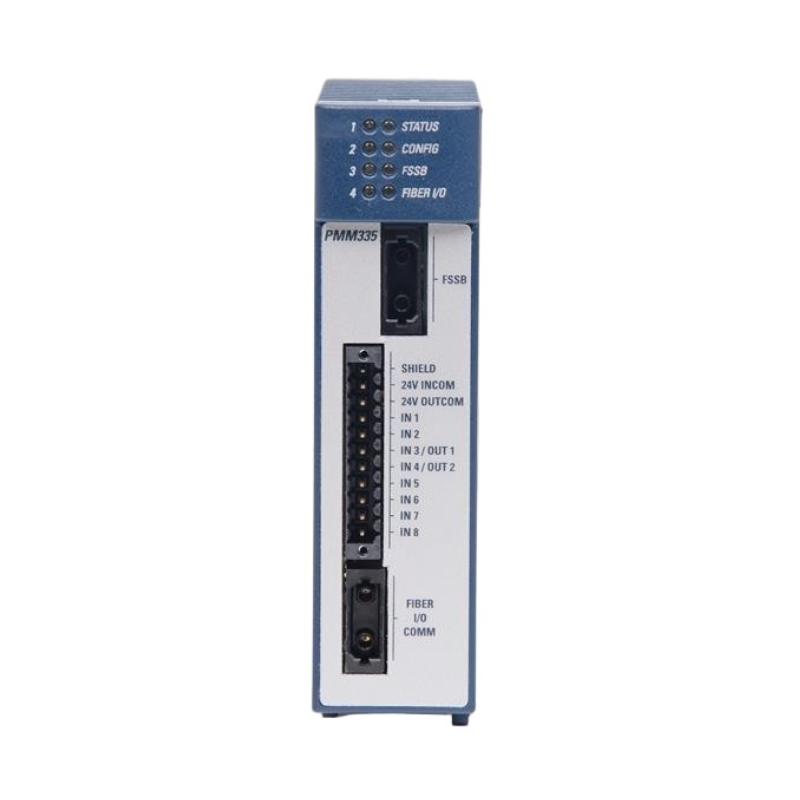
Product Overview
The GE IC695PMM335 is a Multi-Axis Motion Controller Module designed for industrial automation systems that require coordinated control of multiple motion axes. Motion control applications are commonly found in machinery where motors, drives, positioning systems, and mechanical mechanisms must operate according to accurately defined movement profiles.
Unlike a conventional PLC application that primarily handles sequential logic and discrete I/O, a motion-control system must also manage position, velocity, acceleration, synchronization, and coordinated movement. A dedicated motion controller module can therefore provide an important interface between the control program and the machine’s motion system.
The specified dimensions of the GE IC695PMM335 are 185 × 120 × 45 mm, with a weight of approximately 0.7 kg.
The module can be integrated into an RX3i-based automation architecture alongside CPUs, I/O modules, communication hardware, power supplies, and other control components. Correct module installation, configuration, motion parameter setup, drive communication, and commissioning are essential for safe and stable operation.
This guide provides practical information about the IC695PMM335, including its system role, technical specifications, motion-control principles, installation, commissioning, troubleshooting, maintenance, and replacement procedures.
Product Identification
| Parameter | Specification |
|---|---|
| Manufacturer | GE |
| Product Family | PACSystems RX3i |
| Model | IC695PMM335 |
| Product Type | Multi-Axis Motion Controller Module |
| Primary Function | Multi-Axis Motion Control |
| Dimensions | 185 × 120 × 45 mm |
| Weight | Approximately 0.7 kg |
| Installation | RX3i Control System |
| Application | Industrial Motion Automation |
| System Role | Motion Control and Axis Coordination |
Technical Specifications
| Technical Item | Specification |
|---|---|
| Product Series | PACSystems RX3i |
| Part Number | IC695PMM335 |
| Module Type | Multi-Axis Motion Controller |
| Height | 185 mm |
| Width | 120 mm |
| Depth | 45 mm |
| Weight | Approximately 0.7 kg |
| Primary Function | Coordinated Motion Control |
| Application | Multi-Axis Industrial Machinery |
| Installation Environment | Industrial Control Cabinet |
| System Architecture | Modular PLC / Motion Control |
What Is the GE IC695PMM335?
The IC695PMM335 is a specialized motion-control module intended for applications in which multiple machine axes must be controlled and coordinated.
A multi-axis machine may contain:
- Servo motors
- Servo drives
- Position feedback devices
- Linear actuators
- Rotary mechanisms
- Conveyors
- Indexing systems
- Cutting tools
- Pick-and-place mechanisms
The motion controller coordinates these elements according to the machine’s control strategy.
A simplified architecture can be represented as:
PLC / Control Application
↓
IC695PMM335 Motion Controller
↓
Motion Network / Drive Interface
↓
Servo Drives
↓
Servo Motors
↓
Mechanical Axes
This architecture allows motion commands to be integrated with the broader PLC control system.
Multi-Axis Motion Control Principle
Motion control generally involves several fundamental parameters.
Position
Position defines where an axis should move.
Velocity
Velocity defines how quickly the axis should travel.
Acceleration
Acceleration determines how quickly the axis reaches its commanded speed.
Deceleration
Deceleration controls how the axis slows down before stopping.
Synchronization
Multiple axes may need to move together according to a coordinated trajectory.
Feedback
Position or velocity feedback allows the control system to compare actual motion with commanded motion.
A simplified closed-loop concept is:
Command Position
↓
Motion Controller
↓
Drive
↓
Motor
↓
Mechanical System
↓
Feedback
↓
Motion Controller
The controller can then evaluate the difference between the commanded and actual conditions.
Why Multi-Axis Control Is Important
Many modern machines require more than simple motor start/stop control.
For example, a packaging machine may require:
- Conveyor synchronization
- Product positioning
- Servo acceleration
- Cutting-axis coordination
- Registration control
- Precise stopping
A coordinated motion controller can help synchronize these operations.
Other examples include CNC-style machinery, material handling systems, robotic mechanisms, printing equipment, and automated assembly machines.
Typical Industrial Applications
The GE IC695PMM335 can be considered for industrial applications involving coordinated machine movement, including:
- Packaging machinery
- Automated assembly
- Material handling
- Conveyor systems
- Printing machinery
- Cutting equipment
- Machine tools
- Pick-and-place systems
- Robotics-related machinery
- Textile machinery
- Semiconductor equipment
- Automated inspection systems
- Production machinery
The appropriate application depends on the complete control architecture and supported motion hardware.
System Integration
A typical motion-control system may include:
| Component | Typical Function |
|---|---|
| RX3i CPU | PLC application control |
| IC695PMM335 | Multi-axis motion control |
| RX3i Power Supply | System power |
| RX3i Backplane | Module interconnection |
| Servo Drives | Motor control |
| Servo Motors | Mechanical movement |
| Encoders | Position feedback |
| Digital I/O | Machine sequencing |
| Analog I/O | Process signals |
| Safety System | Machine protection |
| Engineering Workstation | Configuration and diagnostics |
The exact configuration should always follow the machine’s engineering design.
Installation Guide
1. Verify the Module
Confirm the product identification:
GE IC695PMM335 Multi-Axis Motion Controller Module
Check the part number against the system documentation before installation.
2. Inspect the Module
Inspect the module for:
- Physical damage
- Damaged connectors
- Housing cracks
- Contamination
- Bent interfaces
- Signs of overheating
Do not install visibly damaged equipment.
3. Verify the Motion Architecture
Before installation, identify:
- Number of motion axes
- Servo drives
- Motor types
- Feedback devices
- Motion network
- Controller configuration
- Axis assignments
- Required motion profiles
4. Prepare the Cabinet
The specified dimensions are:
185 × 120 × 45 mm
Provide adequate space for:
- Module installation
- Adjacent modules
- Communication cables
- Ventilation
- Maintenance access
Keep the module away from excessive heat and strong sources of electromagnetic interference.
5. Back Up Existing Configuration
For an existing machine, back up:
- PLC program
- Motion configuration
- Axis parameters
- Drive parameters
- Network configuration
- Motion profiles
- Diagnostic information
This information can significantly simplify recovery after hardware replacement.
6. Shut Down the Machine
Before installing the module:
- Stop automatic operation.
- Place all axes in a safe condition.
- Disable motion commands.
- Remove system power.
- Verify zero-energy conditions where required.
- Apply appropriate lockout/tagout procedures.
Motion systems require particular attention because stored mechanical or electrical energy may remain even after the controller is powered down.
7. Install the Module
Install the IC695PMM335 in the designated RX3i system position.
Verify:
- Correct orientation
- Proper alignment
- Secure seating
- Correct module position
- Proper mechanical retention
Do not force the module into its interface.
8. Connect Motion Communication
Connect the motion-control communication path according to the approved system design.
Check:
- Correct ports
- Cable condition
- Connector engagement
- Cable routing
- Shielding
- Network topology
9. Connect Feedback and Drive Equipment
Verify all associated drive and feedback connections.
Check:
- Servo-drive communication
- Encoder or feedback wiring
- Axis identification
- Motor connections
- Drive enable circuits
10. Configure the Motion System
Load the validated motion configuration.
Typical parameters may include:
- Axis assignments
- Scaling
- Position units
- Velocity limits
- Acceleration
- Deceleration
- Travel limits
- Homing behavior
- Feedback parameters
- Drive settings
The actual parameter set depends on the machine design.
Motion System Commissioning
Step 1 — Mechanical Inspection
Verify that motors, couplings, linear mechanisms, and machine components are correctly installed.
Step 2 — Electrical Inspection
Check:
- Power
- Drive wiring
- Feedback wiring
- Emergency-stop circuits
- Safety devices
Step 3 — Module Startup
Power the control system and verify module status.
Step 4 — Communication Verification
Confirm communication between the motion controller and associated drive system.
Step 5 — Axis Identification
Verify that each configured axis corresponds to the correct physical machine axis.
Step 6 — Feedback Verification
Confirm that actual position feedback changes correctly when an axis moves.
Step 7 — Jog Test
Perform a controlled low-speed jog test.
Step 8 — Direction Test
Verify that commanded positive and negative movement corresponds to the intended physical direction.
Step 9 — Homing Test
Perform the approved homing procedure.
Step 10 — Motion Profile Test
Test acceleration, velocity, deceleration, and positioning.
Step 11 — Multi-Axis Synchronization
Test coordinated movement between the configured axes.
Step 12 — Full Machine Test
Run the machine under controlled conditions before returning it to normal production.
Troubleshooting Guide
Fault 1 — Motion Controller Is Not Recognized
Possible causes:
- Module not properly seated
- Backplane connection problem
- Power issue
- Configuration mismatch
- Hardware fault
Recommended Checks
- Verify system power.
- Check module seating.
- Inspect the backplane interface.
- Review controller diagnostics.
- Compare the installed hardware with the configuration.
Fault 2 — Servo Drive Cannot Be Controlled
Possible causes:
- Communication failure
- Incorrect drive configuration
- Axis assignment error
- Drive enable problem
- Network connection problem
Check the communication path:
Motion Controller → Network → Drive → Motor
Fault 3 — Axis Does Not Move
Possible causes:
- Servo not enabled
- Safety circuit active
- Drive fault
- Motion command problem
- Travel limit active
- Incorrect axis configuration
Before troubleshooting the controller, verify that the drive and machine safety conditions permit movement.
Fault 4 — Axis Moves in the Wrong Direction
Possible causes:
- Incorrect direction configuration
- Motor wiring issue
- Feedback polarity configuration
- Incorrect axis setup
Stop the machine and correct the configuration before continuing motion tests.
Fault 5 — Position Feedback Is Incorrect
Possible causes:
- Feedback wiring problem
- Encoder issue
- Incorrect scaling
- Incorrect feedback configuration
- Mechanical coupling problem
Compare commanded movement with actual feedback.
Fault 6 — Position Error Becomes Excessive
Possible causes:
- Incorrect tuning
- Excessive mechanical load
- Acceleration too high
- Drive configuration issue
- Mechanical obstruction
- Feedback problem
Investigate both the motion parameters and mechanical system.
Fault 7 — Motion Is Jerky or Unstable
Possible causes:
- Incorrect acceleration settings
- Incorrect velocity parameters
- Mechanical backlash
- Servo tuning issue
- Feedback noise
- Mechanical resonance
Check whether the problem occurs during acceleration, constant-speed movement, or deceleration.
Fault 8 — Multi-Axis Synchronization Is Poor
Possible causes:
- Incorrect axis configuration
- Communication timing problem
- Incorrect scaling
- Different motion parameters
- Mechanical mismatch
Verify that all axes use compatible units, scaling, and synchronization settings.
Fault 9 — Axis Suddenly Stops During Operation
Possible causes:
- Drive fault
- Safety circuit activation
- Communication loss
- Limit switch activation
- Feedback failure
- Controller fault
Review the event sequence and diagnostic information before resetting the system.
Fault 10 — Motion Works During Jogging but Fails During Automatic Operation
Possible causes:
- Incorrect motion program
- Incorrect position parameters
- Sequence logic problem
- Synchronization configuration
- Automatic-mode interlock
Compare manual and automatic operating conditions.
Fault 11 — Communication Drops Intermittently
Possible causes:
- Loose connector
- Damaged cable
- Electrical interference
- Network equipment problem
- Improper cable routing
- Grounding issue
Inspect the physical communication network first.
Fault 12 — Axis Fault Appears After Module Replacement
Possible causes:
- Motion configuration not restored
- Incorrect axis mapping
- Incorrect scaling
- Incorrect drive parameters
- Communication configuration mismatch
Compare the replacement system configuration with the previous validated configuration.
Motion Troubleshooting Workflow
A structured diagnostic sequence is:
Power
↓
RX3i Backplane
↓
IC695PMM335
↓
Motion Communication
↓
Servo Drive
↓
Motor
↓
Feedback Device
↓
Mechanical System
↓
Motion Program
↓
Machine Process
This method helps isolate whether the problem originates in the controller, communication system, drive, feedback device, mechanical system, or application logic.
Preventive Maintenance
Module Inspection
Inspect:
- Housing
- Connectors
- Module seating
- Status indicators
- Signs of overheating
Communication Inspection
Check:
- Motion cables
- Connectors
- Shielding
- Routing
- Network condition
Drive Inspection
Monitor:
- Drive status
- Fault history
- Motor condition
- Temperature
- Connections
Mechanical Inspection
Check:
- Couplings
- Belts
- Gears
- Linear guides
- Bearings
- Mechanical alignment
Feedback Inspection
Check:
- Encoder connections
- Feedback cables
- Position stability
- Signal integrity
Preventive Maintenance Checklist
| Inspection Item | Recommended Action |
|---|---|
| IC695PMM335 | Inspect physical condition |
| Module Seating | Verify secure installation |
| Motion Network | Check communication stability |
| Drive Connections | Inspect cables and connectors |
| Feedback Wiring | Inspect encoder connections |
| Servo Drives | Review fault history |
| Motors | Check operating condition |
| Mechanical System | Inspect alignment and wear |
| Safety Circuits | Verify operation |
| Motion Parameters | Maintain configuration backup |
| Cabinet Environment | Monitor temperature and contamination |
| Diagnostic Logs | Review recurring motion faults |
Motion Controller Replacement Procedure
Step 1 — Back Up the System
Save:
- PLC program
- Motion configuration
- Axis parameters
- Drive parameters
- Network settings
- Machine-specific motion profiles
Step 2 — Record Axis Configuration
Document:
- Axis names
- Axis assignments
- Drive assignments
- Feedback devices
- Scaling
- Homing parameters
- Motion limits
Step 3 — Stop the Machine
Bring the machine to a safe condition.
Step 4 — Remove Energy
Shut down power and follow the machine’s lockout/tagout procedure.
Step 5 — Label Connections
Identify communication and associated connections before removal.
Step 6 — Remove the Existing Module
Carefully remove the existing motion controller.
Step 7 — Inspect the Backplane
Check the module interface for damage or contamination.
Step 8 — Install the Replacement
Install the replacement IC695PMM335.
Step 9 — Restore Connections
Reconnect the motion communication system.
Step 10 — Restore Configuration
Load the validated controller and motion configuration.
Step 11 — Verify Axis Mapping
Confirm that every logical axis corresponds to the correct physical axis.
Step 12 — Verify Feedback
Check actual position feedback.
Step 13 — Perform Low-Speed Testing
Test individual axes at low speed before attempting coordinated movement.
Step 14 — Test Multi-Axis Motion
Verify synchronization and coordinated motion.
Step 15 — Return to Production
Only return the machine to normal operation after all required tests are successful.
Key Advantages
- Designed for multi-axis industrial motion control
- Supports coordinated machine movement
- Integrates motion control with modular automation architectures
- Suitable for applications requiring positioning and synchronization
- Supports structured servo-control architectures
- Can simplify centralized management of multiple motion axes
- Compact 185 × 120 × 45 mm dimensions
- Approximately 0.7 kg weight
- Suitable for industrial control cabinet installation
- Supports integration of motion functions into broader PLC-based systems
Frequently Asked Questions
What is the GE IC695PMM335?
The GE IC695PMM335 is a Multi-Axis Motion Controller Module designed for industrial automation systems requiring coordinated motion control.
What are its dimensions?
The specified dimensions are:
185 × 120 × 45 mm
What is the weight?
Approximately 0.7 kg.
What is the purpose of a multi-axis motion controller?
It coordinates multiple machine axes by managing motion commands such as position, velocity, acceleration, deceleration, and synchronization.
Why does an axis fail to move?
Check drive status, safety conditions, communication, axis configuration, motion commands, travel limits, and feedback.
Why is position feedback inaccurate?
Possible causes include feedback wiring, encoder problems, incorrect scaling, configuration errors, or mechanical coupling problems.
Why is multi-axis synchronization inaccurate?
Check axis scaling, motion parameters, communication performance, synchronization configuration, and mechanical differences between axes.
What should be backed up before replacing the IC695PMM335?
The PLC program, motion configuration, axis parameters, drive parameters, network configuration, and machine-specific motion settings should be preserved.
Why should low-speed testing be performed after replacement?
Low-speed testing provides a controlled way to verify axis direction, feedback, limits, drive response, and mechanical behavior before full-speed operation.
Conclusion
The GE IC695PMM335 Multi-Axis Motion Controller Module is intended for industrial automation systems where several machine axes must be coordinated with accurate and repeatable motion. With specified dimensions of 185 × 120 × 45 mm and a weight of approximately 0.7 kg, it provides a compact module for integrating motion-control functionality into an RX3i-based automation architecture.
Multi-axis motion applications require more than conventional sequence logic. Position, velocity, acceleration, deceleration, synchronization, feedback, drive control, and machine safety all influence overall performance. For this reason, successful installation requires coordination between the motion controller, servo drives, motors, feedback devices, mechanical equipment, and PLC application.
During commissioning, individual axes should be verified before coordinated motion is tested. Direction, feedback, homing, limits, drive enable conditions, and motion parameters should be confirmed before higher-speed operation.
When troubleshooting the IC695PMM335, technicians should follow the complete motion path rather than focusing exclusively on the controller. Communication, drive status, feedback, mechanical conditions, configuration, and application logic can all produce similar motion symptoms.
With appropriate configuration management, preventive maintenance, controlled commissioning, and systematic troubleshooting, the IC695PMM335 can form an important part of a reliable multi-axis industrial motion-control system.