

ProductPRODUCT
Featured products


Contact Us
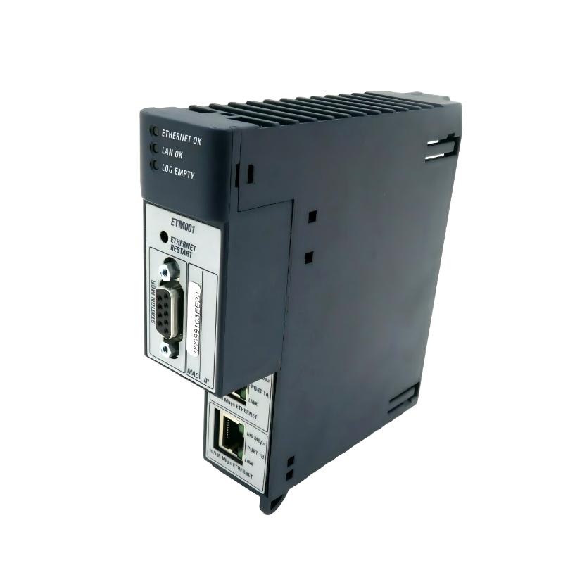
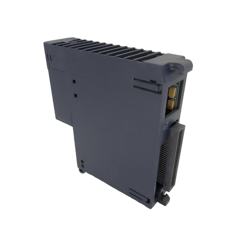
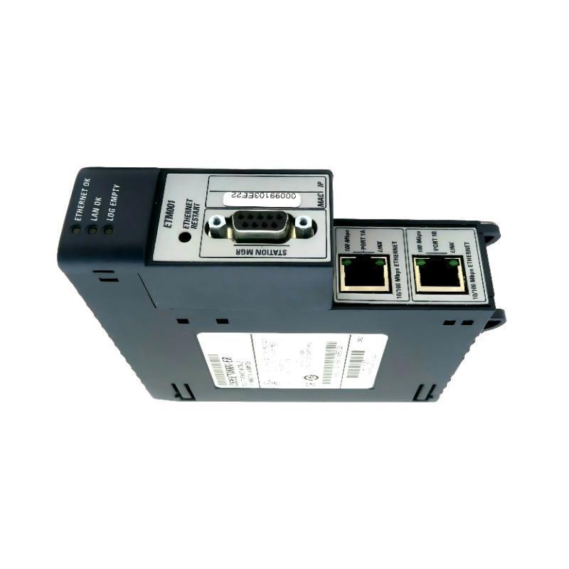
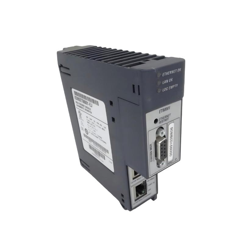
- GE
- IC695NKT001
- Ethernet Remote I/O Expansion Kit
- USA
- 130 × 100 × 60 mm
- 1.08 kg
- Xiamen, China
- New & In Stock
- T/T, PayPal, Western Union
- 1 Year
- 1-3 Working Days
- DHL, UPS, TNT, FedEx and EMS.
- 24-Hour Service
- COO
- 49
Our advantage

Global Logistics
We have a 10-year logistics and express cooperation agreement, so our products can be shipped to any place in the world.

Brand new and original
Our products are imported in bulk from the place of origin. Because of the cooperative relationship, our products are all original and 100% new.

24-hour service
We provide 7*24 hours service to our customers. We will be there whenever you need us.

Price advantage
All our products are priced very favorably because we have our own warehouse and supply.
| Company Information | |||
| [email protected] | |||
| Mobile | +8615980777398 | ||
| +8615980777398 | |||
| 15980777398 |
Product Overview
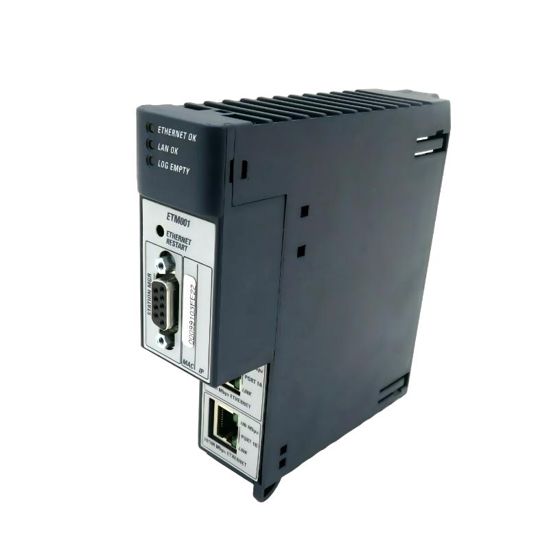
The GE IC695NKT001 is an Ethernet Remote I/O Expansion Kit designed for industrial automation architectures that require distributed I/O communication over an Ethernet-based network. By extending I/O functionality away from the central controller, the kit can help organize field devices into remote stations while allowing process data to be exchanged with the main control system.
In a distributed automation installation, placing every I/O point beside the central PLC is not always practical. Machines may be physically separated, production lines may cover large areas, or field instruments may be located close to remote equipment. An Ethernet remote I/O architecture allows these devices to be grouped into remote I/O stations and connected to the control network.
The GE IC695NKT001 has specified dimensions of 130 × 100 × 60 mm and a weight of approximately 1.08 kg.
The kit can therefore be considered part of the communication infrastructure between the central control system and distributed I/O equipment. Correct network configuration, power, cable installation, module arrangement, and diagnostic monitoring are essential for dependable operation.
This guide provides practical information covering product identification, technical characteristics, system architecture, installation, commissioning, troubleshooting, preventive maintenance, and replacement.
Product Identification
| Parameter | Specification |
|---|---|
| Manufacturer | GE |
| Product Family | PACSystems RX3i |
| Model | IC695NKT001 |
| Product Type | Ethernet Remote I/O Expansion Kit |
| Primary Function | Remote I/O Expansion |
| Communication | Ethernet-Based Industrial Network |
| Dimensions | 130 × 100 × 60 mm |
| Weight | 1.08 kg |
| Installation | Industrial Control System |
| Application | Distributed I/O |
| System Role | Remote I/O Network Interface |
Technical Specifications
| Technical Item | Specification |
|---|---|
| Product Series | PACSystems RX3i |
| Part Number | IC695NKT001 |
| Module / Kit Type | Ethernet Remote I/O Expansion Kit |
| Height | 130 mm |
| Width | 100 mm |
| Depth | 60 mm |
| Weight | Approximately 1.08 kg |
| Primary Function | Remote I/O Expansion |
| Communication Type | Ethernet |
| Installation Environment | Industrial Control Cabinet |
| System Architecture | Distributed Automation |
| Application | Remote I/O and Industrial Networking |
What Is the GE IC695NKT001?
The IC695NKT001 is an Ethernet remote I/O expansion kit intended for applications where I/O devices need to be located away from the main control cabinet or controller.
A conventional centralized I/O architecture can be represented as:
Field Devices
↓
Central I/O
↓
PLC Controller
↓
Control System
With remote I/O, the architecture can instead be organized as:
Field Devices
↓
Remote I/O Station
↓
Ethernet Network
↓
Central Controller
↓
PLC Application
This approach can reduce long field-wiring runs and provide a more organized architecture for geographically distributed machines and processes.
How Ethernet Remote I/O Works
The operation of a remote I/O architecture can be divided into several stages.
1. Field Signal Acquisition
Sensors and other field devices generate electrical signals.
2. Remote I/O Processing
The remote I/O station receives these signals through the installed I/O modules.
3. Network Data Transfer
The remote station exchanges I/O data with the central control system through the Ethernet network.
4. Controller Processing
The PLC processes the received input information according to the application program.
5. Output Command Transmission
The controller generates output commands that are transferred back through the network.
6. Remote Output Operation
Remote output modules operate the connected actuators and equipment.
The resulting communication path is:
Sensor → Remote I/O → Ethernet → Controller → Ethernet → Remote I/O → Actuator
Advantages of Remote I/O Architecture
Using remote I/O can provide several practical benefits.
Reduced Field Wiring
Instead of bringing every field signal back to a central cabinet, field devices can be connected to a nearby remote I/O station.
Flexible Equipment Placement
Remote I/O stations can be positioned closer to machines and production equipment.
Easier System Expansion
Additional remote I/O stations can be integrated into an established network architecture when the system design allows it.
Better Cabinet Organization
Separating field interfaces from the central controller can simplify cabinet layouts.
Improved Maintenance
Grouping field connections near the associated equipment can make troubleshooting more systematic.
Typical Industrial Applications
The GE IC695NKT001 can be used in automation architectures involving:
- Factory automation
- Production lines
- Packaging machinery
- Material handling
- Conveyor systems
- Water treatment
- Process automation
- Power-related automation
- Chemical processing
- Oil and gas
- Food and beverage manufacturing
- Pharmaceutical production
- Large industrial facilities
Remote I/O is particularly useful when machines or field devices are physically separated from the main control cabinet.
System Integration
A typical remote I/O architecture may include:
| Component | Typical Function |
|---|---|
| RX3i Controller | Central control processing |
| IC695NKT001 | Ethernet remote I/O expansion |
| Remote I/O Station | Distributed signal interface |
| Ethernet Network | Data communication |
| RX3i Power Supply | System power |
| Digital Input Modules | Discrete signal acquisition |
| Digital Output Modules | Discrete control |
| Analog Input Modules | Process measurement |
| Analog Output Modules | Analog control |
| Network Switch | Network interconnection |
| Sensors | Field signal generation |
| Actuators | Physical process control |
The exact hardware configuration depends on the control-system design.
Installation Guide
1. Verify the Product
Confirm:
GE IC695NKT001 Ethernet Remote I/O Expansion Kit
Verify the part number against the engineering documentation before installation.
2. Inspect the Kit
Inspect the equipment for:
- Physical damage
- Damaged connectors
- Damaged mounting points
- Signs of contamination
- Signs of overheating
- Packaging or transport damage
Do not install visibly damaged equipment.
3. Confirm the Network Architecture
Before installation, determine:
- Remote I/O location
- Central controller location
- Ethernet network topology
- Network switch arrangement
- Remote I/O modules
- Power supply
- Required network configuration
4. Prepare the Cabinet
Specified dimensions:
130 × 100 × 60 mm
Provide sufficient space for:
- Installation
- Ethernet cable routing
- Power connections
- Adjacent modules
- Ventilation
- Inspection
- Maintenance
Avoid excessive heat, moisture, vibration, and corrosive contamination.
5. Plan the Remote I/O Location
Place the remote I/O station close enough to the associated field devices to provide practical wiring distances.
Consider:
- Cable length
- Environmental conditions
- Maintenance access
- Temperature
- Vibration
- Electrical noise
- Network accessibility
6. Back Up the Existing Configuration
For an existing installation, save:
- PLC program
- Hardware configuration
- Ethernet configuration
- Remote I/O configuration
- Network topology documentation
- Diagnostic records
7. Shut Down the System
Before installation:
- Stop the controlled process.
- Shut down the control system.
- Remove power according to the approved procedure.
- Verify the equipment is safe to service.
- Apply lockout/tagout procedures where required.
8. Install the Remote I/O Expansion Equipment
Install the IC695NKT001 according to the approved mechanical arrangement.
Verify:
- Correct orientation
- Secure mounting
- Proper module alignment
- Adequate clearance
- Accessible connectors
9. Connect the Ethernet Network
Connect the Ethernet communication path.
Check:
- Correct network port
- Cable integrity
- Connector engagement
- Cable routing
- Network switch connection
Avoid routing Ethernet communication cables directly alongside high-current motor wiring where practical.
10. Connect Remote I/O Modules
Install and connect the required remote I/O modules according to the approved architecture.
Verify:
- Module arrangement
- I/O addresses
- Module seating
- Power requirements
- Field wiring
11. Connect Field Devices
Connect sensors and actuators to the appropriate I/O channels.
Label field wiring clearly to simplify future troubleshooting.
12. Restore Power
After all connections are verified:
- Restore power.
- Observe system status.
- Check remote I/O status.
- Check Ethernet communication.
- Review controller diagnostics.
Ethernet Network Installation Considerations
Reliable remote I/O operation depends heavily on network quality.
Cable Routing
Keep network cables away from strong electrical noise sources whenever possible.
Connector Security
Loose Ethernet connectors can cause intermittent communication.
Network Topology
Use the topology specified by the engineering design.
Network Equipment
Verify that network switches and other communication devices are operating correctly.
Grounding and Shielding
Follow the installation requirements for the selected Ethernet cabling and industrial environment.
Commissioning Procedure
Step 1 — Physical Inspection
Verify all hardware is securely installed.
Step 2 — Power Verification
Confirm stable power at the remote I/O station.
Step 3 — Network Startup
Power the Ethernet communication infrastructure.
Step 4 — Remote Station Recognition
Verify that the central controller can identify the remote I/O system.
Step 5 — Network Communication Test
Check communication between:
Controller ↔ Ethernet Network ↔ Remote I/O
Step 6 — Input Test
Activate representative sensors and confirm that the controller receives the expected input data.
Step 7 — Output Test
Command representative outputs and verify field-device response.
Step 8 — Diagnostic Check
Review controller and remote I/O diagnostics.
Step 9 — Process Test
Operate the machine or process under supervised conditions.
Troubleshooting Guide
Fault 1 — Remote I/O Station Does Not Start
Possible causes:
- Power supply problem
- Incorrect wiring
- Loose connection
- Hardware fault
- Incorrect installation
Recommended Checks
- Verify power.
- Check wiring.
- Inspect module connections.
- Check status indicators.
- Review diagnostics.
Fault 2 — Remote I/O Is Not Detected
Possible causes:
- Ethernet communication failure
- Incorrect configuration
- Network switch problem
- Incorrect network addressing
- Remote I/O hardware fault
Check the complete communication path between the controller and remote station.
Fault 3 — Ethernet Communication Is Intermittent
Possible causes:
- Damaged cable
- Loose connector
- Electrical interference
- Network switch problem
- Power instability
- Environmental conditions
Inspect the physical network before changing configuration parameters.
Fault 4 — Remote Inputs Are Not Updating
Possible causes:
- Sensor failure
- I/O module problem
- Remote station communication failure
- Incorrect I/O configuration
- Field wiring problem
Use the following diagnostic sequence:
Sensor → I/O Channel → Remote Station → Ethernet → Controller
Fault 5 — Remote Outputs Do Not Operate
Possible causes:
- Incorrect output configuration
- Output module problem
- Network communication loss
- Field wiring problem
- Actuator failure
Test the output path step by step.
Fault 6 — Some Remote I/O Channels Work but Others Do Not
Possible causes:
- Individual I/O module problem
- Channel wiring fault
- Incorrect configuration
- Local power issue
- Damaged field device
This type of fault does not necessarily indicate an Ethernet problem.
Fault 7 — Network Communication Drops During Machine Operation
Possible causes:
- Electrical interference
- Vibration
- Loose connector
- Damaged network cable
- Network equipment overload or failure
- Power fluctuation
Observe whether the communication fault occurs only when specific machines or motors start.
Fault 8 — I/O Data Is Incorrect
Possible causes:
- Incorrect channel mapping
- Wrong I/O configuration
- Sensor fault
- Wiring error
- Application logic problem
Compare the expected field signal with the actual I/O data at each stage.
Fault 9 — Communication Fails After Configuration Changes
Possible causes:
- Incorrect network configuration
- Incorrect remote I/O configuration
- Address conflict
- Configuration mismatch
- Incorrect module arrangement
Restore the last known-good configuration if necessary and then make changes systematically.
Fault 10 — Communication Fails After Hardware Replacement
Possible causes:
- Configuration not restored
- Incorrect module installation
- Incorrect network connection
- Wrong I/O arrangement
- Cable problem
Compare the replacement installation with the original documented configuration.
Diagnostic Workflow
A practical troubleshooting sequence is:
Power Supply
↓
Remote I/O Hardware
↓
IC695NKT001
↓
Ethernet Cable
↓
Network Switch
↓
Network Configuration
↓
Remote I/O Modules
↓
RX3i Controller
↓
PLC Application
↓
Field Devices
This approach helps determine whether the problem is caused by hardware, communication, configuration, or field equipment.
Preventive Maintenance
Hardware Inspection
Inspect:
- Expansion kit
- Mounting
- Connectors
- Remote I/O modules
- Power connections
Ethernet Network Inspection
Check:
- Cable condition
- Connector security
- Network switches
- Cable routing
- Network status
I/O Inspection
Verify:
- Sensor connections
- Actuator wiring
- Module seating
- Channel operation
- I/O diagnostics
Environmental Inspection
Monitor:
- Temperature
- Dust
- Moisture
- Vibration
- Electrical interference
- Ventilation
Preventive Maintenance Checklist
| Inspection Item | Recommended Action |
|---|---|
| IC695NKT001 | Inspect physical condition |
| Mounting | Verify secure installation |
| Ethernet Cables | Inspect for damage |
| Network Connectors | Check connection security |
| Network Switches | Verify operating status |
| Remote I/O Modules | Check module seating |
| Field Wiring | Inspect connections |
| Power Supply | Monitor stability |
| Cabinet Temperature | Monitor operating conditions |
| PLC Configuration | Maintain current backup |
| Network Configuration | Maintain documentation |
| Diagnostics | Review communication faults |
Remote I/O Expansion Kit Replacement Procedure
Step 1 — Back Up the System
Save:
- PLC application
- Hardware configuration
- Ethernet configuration
- Remote I/O configuration
Step 2 — Document the Existing Network
Record:
- Ethernet connections
- Network topology
- Remote I/O location
- Module arrangement
- Relevant configuration information
Step 3 — Stop the Process
Place the machine or process in a safe condition.
Step 4 — Remove Power
Follow the approved shutdown and lockout/tagout procedure.
Step 5 — Label Network and I/O Connections
Clearly identify cables before disconnection.
Step 6 — Remove the Existing Equipment
Disconnect network and power connections and remove the existing unit.
Step 7 — Inspect Connections
Check mounting points, cables, connectors, and adjacent hardware.
Step 8 — Install the Replacement
Install the replacement IC695NKT001.
Step 9 — Reconnect the Network
Restore Ethernet connections according to the original configuration.
Step 10 — Restore Remote I/O Connections
Reconnect the required I/O modules and field wiring.
Step 11 — Restore Configuration
Load the validated system configuration.
Step 12 — Restore Power
Power up the system.
Step 13 — Verify Network Communication
Confirm:
Controller ↔ Network ↔ Remote I/O
Step 14 — Test I/O
Verify representative inputs and outputs.
Step 15 — Return to Service
Return the process to normal operation after all required checks are completed.
Key Advantages
- Designed for Ethernet-based remote I/O architectures
- Supports distributed industrial automation
- Helps extend I/O away from the central controller
- Can reduce long field-wiring runs
- Supports organized remote I/O installations
- Compact 130 × 100 × 60 mm form factor
- Approximately 1.08 kg weight
- Suitable for machine and process automation
- Facilitates centralized control of distributed field devices
- Supports structured industrial network integration
Frequently Asked Questions
What is the GE IC695NKT001?
The GE IC695NKT001 is an Ethernet Remote I/O Expansion Kit designed to support distributed I/O architectures in industrial automation systems.
What are the dimensions?
The specified dimensions are:
130 × 100 × 60 mm
What is the weight?
Approximately 1.08 kg.
Why use Ethernet remote I/O?
Remote I/O allows field signals to be collected closer to machines and process equipment while transferring the data to the central controller through an industrial Ethernet network.
What causes remote I/O communication failure?
Possible causes include network cable problems, loose connectors, power failures, incorrect configuration, network switch problems, or hardware faults.
Why do remote inputs fail to update?
Check the sensor, field wiring, I/O module, remote station, Ethernet connection, network configuration, and controller data path.
Why do remote outputs not operate?
Check controller commands, network communication, remote I/O configuration, output module status, field wiring, and the connected actuator.
What causes intermittent Ethernet communication?
Loose connectors, damaged cables, electrical interference, unstable power, network equipment problems, or environmental conditions can cause intermittent communication.
What should be backed up before replacing the IC695NKT001?
Maintain current copies of the PLC program, hardware configuration, Ethernet configuration, remote I/O configuration, and network documentation.
Conclusion
The GE IC695NKT001 Ethernet Remote I/O Expansion Kit is intended for industrial automation systems where I/O needs to be distributed across a plant, production line, or machine installation. With specified dimensions of 130 × 100 × 60 mm and a weight of approximately 1.08 kg, it provides a compact solution for integrating remote I/O into an Ethernet-based control architecture.
Remote I/O can provide important practical advantages by placing field interfaces closer to sensors and actuators. This can reduce long field-wiring runs, simplify cabinet organization, and provide a structured way to connect geographically distributed equipment to a central controller.
Reliable operation depends on more than the expansion kit itself. The complete communication path—including power, remote I/O hardware, Ethernet cables, network switches, configuration, I/O modules, controller, and field devices—must be correctly installed and maintained.
During commissioning, technicians should verify network communication before testing individual I/O channels. During troubleshooting, following the signal path from the field device through the remote I/O station and Ethernet network to the controller can help quickly identify the actual fault location.
With appropriate installation practices, accurate network documentation, regular preventive maintenance, reliable configuration backups, and systematic troubleshooting, the IC695NKT001 can support a scalable and maintainable distributed I/O architecture for industrial automation applications.