

ProductPRODUCT
Featured products
Contact Us
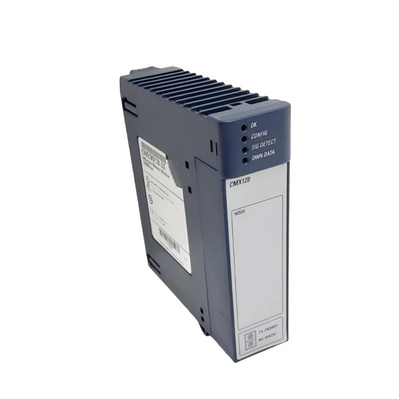
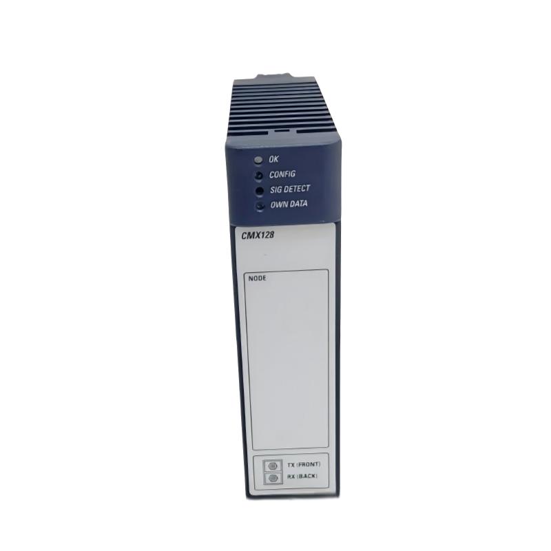
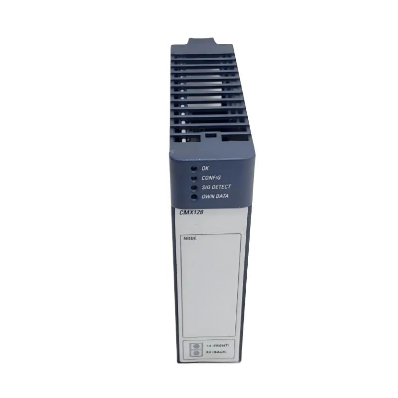
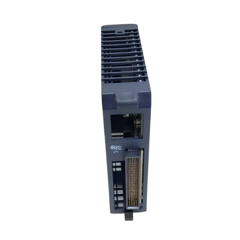
- GE
- IC695CMX128
- RX3i Control Memory Switching Module
- USA
- 50 × 160 × 120 mm
- 0.45 kg
- Xiamen, China
- New & In Stock
- T/T, PayPal, Western Union
- 1 Year
- 1-3 Working Days
- DHL, UPS, TNT, FedEx and EMS.
- 24-Hour Service
- COO
- 39
Our advantage

Global Logistics
We have a 10-year logistics and express cooperation agreement, so our products can be shipped to any place in the world.

Brand new and original
Our products are imported in bulk from the place of origin. Because of the cooperative relationship, our products are all original and 100% new.

24-hour service
We provide 7*24 hours service to our customers. We will be there whenever you need us.

Price advantage
All our products are priced very favorably because we have our own warehouse and supply.
| Company Information | |||
| [email protected] | |||
| Mobile | +8615980777398 | ||
| +8615980777398 | |||
| 15980777398 |
Product Overview
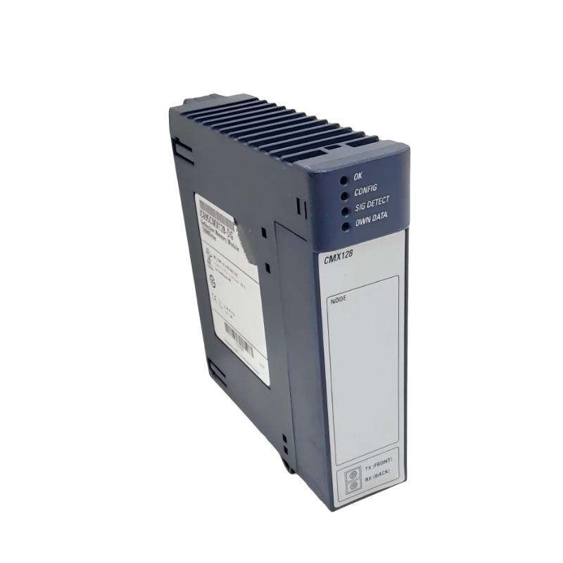
The GE IC695CMX128 is an RX3i Control Memory Switching Module designed for use within GE PACSystems RX3i industrial automation architectures. It is intended to support control-system memory management and switching functions within an RX3i-based control environment, providing an important hardware interface for applications that require organized control memory handling and dependable system operation.
In complex PLC systems, memory-related hardware must operate consistently with the controller, rack infrastructure, and application configuration. A properly installed control memory switching module can contribute to stable system operation, while an incorrect configuration, poor module connection, or hardware fault may result in diagnostic alarms or unexpected controller behavior.
The IC695CMX128 has compact dimensions of 50 × 160 × 120 mm and a specified weight of approximately 0.45 kg. Its rack-mounted construction makes it suitable for industrial control cabinets where space efficiency, accessibility, and reliable module integration are important.
This guide covers the product’s general function, installation considerations, commissioning procedures, troubleshooting methods, preventive maintenance, and replacement practices.
Product Identification
| Parameter | Specification |
|---|---|
| Manufacturer | GE |
| Product Family | PACSystems RX3i |
| Model | IC695CMX128 |
| Product Type | RX3i Control Memory Switching Module |
| Primary Function | Control Memory Switching |
| Dimensions | 50 × 160 × 120 mm |
| Weight | 0.45 kg |
| Installation | RX3i Control System |
| Mounting | Rack-Based Installation |
| Application | Industrial Automation |
| System Platform | PACSystems RX3i |
Technical Specifications
| Technical Item | Specification |
|---|---|
| Product Series | PACSystems RX3i |
| Model Number | IC695CMX128 |
| Module Type | Control Memory Switching Module |
| Function | Control Memory Switching |
| Height | 50 mm |
| Width | 160 mm |
| Depth | 120 mm |
| Weight | Approximately 0.45 kg |
| Installation Environment | Industrial Control Cabinet |
| System Architecture | RX3i |
| Maintenance | Replaceable Industrial Module |
Main Function
The IC695CMX128 is used as part of the RX3i control-system architecture to support control memory switching functions.
Its role can be considered within the broader PLC architecture:
RX3i Controller
↓
Control / Memory Management
↓
IC695CMX128
↓
System Memory Switching Function
↓
Control Application
The exact behavior of the module depends on the surrounding RX3i system architecture, controller configuration, and application requirements.
Role in an RX3i Control System
Control memory is essential to PLC operation because the controller relies on stored information for executing application logic and maintaining system functions.
A control memory switching module can be particularly important in applications where controlled access to different memory states or memory resources is required.
The module may therefore be considered part of the system infrastructure alongside:
- RX3i CPU modules
- RX3i power supplies
- RX3i backplates
- Communication modules
- Digital I/O modules
- Analog I/O modules
- Programming and engineering systems
Maintaining reliable communication and physical connections between these components is essential for stable operation.
Working Principle
The IC695CMX128 operates as a hardware component within the RX3i control architecture.
A simplified operating sequence is:
- The RX3i system initializes the installed hardware.
- The controller identifies configured system components.
- The control memory switching function becomes available according to the system configuration.
- The PLC executes the programmed control application.
- Memory-related operations are managed according to the configured system architecture.
- Diagnostic information is made available when abnormal conditions occur.
Because memory-related functions can affect overall controller operation, troubleshooting should always begin with the system configuration and diagnostic information rather than replacing the module immediately.
Typical Industrial Applications
The GE IC695CMX128 can be used in industrial automation environments based on the RX3i platform, including:
- Factory automation
- Machine control
- Process control
- Power generation
- Water treatment
- Chemical processing
- Oil and gas
- Pharmaceutical production
- Food and beverage manufacturing
- Mining
- Steel production
- Material handling
- Packaging systems
It is particularly relevant to control architectures where reliable memory management is part of the overall system design.
Installation Guide
1. Verify the Module
Confirm the product identification:
GE IC695CMX128 RX3i Control Memory Switching Module
Check the part number carefully before installation.
2. Confirm System Requirements
Before installation, verify that the existing RX3i system architecture is designed to accommodate the module.
Review:
- CPU configuration
- Rack arrangement
- Power supply
- Module slot
- Engineering configuration
- Application requirements
3. Inspect the Module
Before installation, inspect:
- Module housing
- Connector area
- Mounting mechanism
- Product label
- Electrical contacts
- Signs of physical damage
Do not install a module with damaged connectors or housing.
4. Prepare the Cabinet
The specified module dimensions are:
50 × 160 × 120 mm
Provide adequate space for:
- Module insertion
- Cable routing
- Ventilation
- Maintenance
- Future replacement
Avoid installing the module where it can be exposed to excessive heat, moisture, vibration, or contamination.
5. Shut Down the System
Before installing the module:
- Stop the PLC application.
- Shut down the control system according to plant procedures.
- Remove power where required.
- Verify safe working conditions.
- Follow applicable lockout/tagout procedures.
6. Install the Module
Insert the IC695CMX128 into the designated RX3i position.
Check:
- Correct alignment
- Complete insertion
- Secure mechanical engagement
- Proper connector engagement
Do not force the module into the rack.
7. Check Module Connections
After installation, inspect the connection between the module and rack.
Ensure that:
- The connector is fully engaged.
- No contacts are visibly damaged.
- The module is mechanically secure.
- The module is installed in the intended location.
8. Configure the System
Update the RX3i hardware configuration as required.
Verify:
- Correct module identification
- Correct slot assignment
- Compatible CPU configuration
- Memory-related system parameters
- Diagnostic settings
9. Restore Power
After completing the installation:
- Restore system power.
- Start the controller.
- Observe module status indicators.
- Verify system initialization.
- Check for diagnostic alarms.
Commissioning Procedure
A controlled commissioning process helps identify installation problems before the system is returned to production.
Step 1 — Hardware Inspection
Confirm that the module is correctly installed.
Step 2 — Configuration Verification
Compare the physical module with the engineering configuration.
Step 3 — Controller Startup
Start the RX3i controller according to the approved procedure.
Step 4 — Module Recognition
Confirm that the controller recognizes the installed module.
Step 5 — Diagnostic Review
Check the controller and engineering software for hardware or configuration alarms.
Step 6 — Memory Function Verification
Verify the intended control memory switching function according to the application’s approved test procedure.
Step 7 — System Test
Run the control system under controlled conditions before returning it to full production.
Troubleshooting Guide
Fault 1 — Module Is Not Recognized
Possible causes include:
- Incorrect installation
- Improper module seating
- Incorrect slot assignment
- Configuration mismatch
- Backplane connection problem
- Module hardware fault
Recommended Checks
- Confirm the model number.
- Inspect module seating.
- Check the hardware configuration.
- Inspect the rack connection.
- Review controller diagnostics.
Fault 2 — Controller Reports a Configuration Error
Possible causes:
- Incorrect module configuration
- Wrong slot assignment
- Incompatible hardware arrangement
- Engineering project does not match the physical system
Compare the actual rack configuration with the downloaded PLC hardware configuration.
Fault 3 — Module Diagnostic Alarm
Possible causes include:
- Hardware fault
- Communication problem
- Configuration error
- Power instability
- Poor rack connection
Review the diagnostic information before replacing the module.
Fault 4 — Memory Switching Function Does Not Operate Correctly
Possible causes:
- Incorrect system configuration
- Application logic problem
- Module connection problem
- Controller issue
- Memory configuration error
Separate the problem into hardware, configuration, and application layers.
Fault 5 — Controller Fails During Startup
If the controller fails during initialization after module installation, inspect:
- Module seating
- Hardware configuration
- Rack power
- Backplane connection
- Module compatibility
If the problem began immediately after module replacement, compare the old and new hardware configuration carefully.
Fault 6 — Intermittent Module Operation
Possible causes:
- Loose connection
- Mechanical vibration
- Contaminated connector
- Rack problem
- Power instability
- Environmental stress
Inspect the physical installation before changing software parameters.
Fault 7 — System Resets Unexpectedly
Possible causes include:
- Unstable power
- Hardware connection problem
- Controller fault
- Rack-level issue
- Environmental interference
Review system diagnostics and power records to identify whether the reset originates from hardware or application behavior.
Fault 8 — Communication Problem
Possible causes:
- Backplane connection failure
- Controller issue
- Module fault
- Configuration mismatch
Check the complete communication path rather than focusing only on the module.
Fault 9 — Fault Appears After Maintenance
If the problem appears immediately after cabinet maintenance, inspect:
- Module seating
- Rack connections
- Wiring
- Power connections
- Configuration changes
Maintenance activities can unintentionally disturb otherwise stable hardware connections.
Fault 10 — Repeated Module Failure
If replacement modules repeatedly exhibit the same problem, do not assume that every replacement module is defective.
Investigate:
- Power quality
- Rack condition
- Environmental conditions
- Electrical interference
- Incorrect configuration
- Mechanical stress
A repeated fault often indicates a system-level problem.
Diagnostic Workflow
A structured diagnostic procedure can be organized as follows:
Power Supply
↓
RX3i Backplate
↓
IC695CMX128
↓
RX3i CPU
↓
Hardware Configuration
↓
Control Memory Function
↓
PLC Application
↓
System Diagnostics
This sequence helps maintenance personnel isolate the problem without unnecessarily replacing multiple components.
Preventive Maintenance
Regular maintenance can improve system reliability.
Mechanical Inspection
Check:
- Module housing
- Mounting mechanism
- Rack alignment
- Connector engagement
- Signs of vibration
Electrical Inspection
Check:
- Power stability
- Grounding
- Connector condition
- Backplane interfaces
Configuration Maintenance
Maintain:
- PLC project backups
- Hardware configuration records
- Module slot documentation
- Diagnostic history
- Approved replacement procedures
Environmental Maintenance
Monitor:
- Cabinet temperature
- Humidity
- Dust
- Vibration
- Corrosive contaminants
- Ventilation
Preventive Maintenance Checklist
| Inspection Item | Recommended Action |
|---|---|
| Module Housing | Inspect for physical damage |
| Connector | Check condition and seating |
| Rack Installation | Verify secure mounting |
| Power Supply | Monitor stability |
| Grounding | Verify system grounding |
| Hardware Configuration | Compare with physical rack |
| Diagnostic Logs | Review periodically |
| Cabinet Temperature | Monitor operating conditions |
| Dust / Contamination | Clean cabinet as required |
| PLC Backup | Maintain current backup |
Replacement Procedure
When replacing an IC695CMX128, use a controlled maintenance procedure.
Step 1
Back up the PLC application and hardware configuration.
Step 2
Record the existing module position.
Step 3
Document relevant system settings.
Step 4
Shut down the controller.
Step 5
Remove system power according to the approved procedure.
Step 6
Remove the existing module.
Step 7
Inspect the rack connector.
Step 8
Install the replacement IC695CMX128.
Step 9
Verify mechanical and electrical engagement.
Step 10
Restore the hardware configuration if required.
Step 11
Restore system power.
Step 12
Check controller recognition.
Step 13
Review diagnostic information.
Step 14
Test the control memory switching function.
Step 15
Perform a complete system test.
Key Advantages
- Designed for RX3i control-system architecture
- Dedicated control memory switching function
- Compact industrial module design
- Rack-based installation
- Easy integration into organized control cabinets
- Suitable for industrial automation environments
- Supports structured control-system architecture
- Straightforward maintenance and replacement
- Provides a dedicated hardware solution for memory-related control functions
Frequently Asked Questions
What is the GE IC695CMX128?
The GE IC695CMX128 is an RX3i Control Memory Switching Module used as part of a GE PACSystems RX3i industrial control architecture.
What are its dimensions?
The specified dimensions are:
50 × 160 × 120 mm
What is the weight?
Approximately 0.45 kg.
What is the primary purpose of this module?
Its primary function is to provide control memory switching within the applicable RX3i system architecture.
Where is the module installed?
It is installed as part of the RX3i rack-based control system and should be placed according to the approved hardware configuration.
Why is the module not recognized?
Possible causes include incorrect installation, poor connector engagement, configuration mismatch, rack problems, or a module fault.
What should be checked before replacing the module?
Check the hardware configuration, module seating, backplane connection, power supply, controller diagnostics, and system environment first.
What can cause intermittent operation?
Loose connections, vibration, contamination, power instability, environmental stress, and rack-level problems can all contribute to intermittent behavior.
Should the PLC project be backed up before replacement?
Yes. A current PLC application and hardware configuration backup should be maintained before performing significant control-system maintenance.
Conclusion
The GE IC695CMX128 RX3i Control Memory Switching Module is a specialized component within the PACSystems RX3i control architecture. With dimensions of 50 × 160 × 120 mm and a weight of approximately 0.45 kg, it provides a compact solution for control-system memory switching requirements.
Reliable operation depends on correct module installation, proper rack engagement, accurate hardware configuration, stable power, and suitable cabinet environmental conditions. When a fault occurs, technicians should use a structured diagnostic approach that evaluates the power supply, rack, module connection, CPU, configuration, and application before concluding that the module itself has failed.
For long-term reliability, regular inspection of module connections, rack hardware, system configuration, environmental conditions, and diagnostic records is recommended. Proper maintenance and controlled replacement procedures can help minimize downtime and maintain dependable RX3i control-system performance.