

- Home
- >
- GE Fanuc
- >
- GE IC695CBL002 Cable
- >
ProductPRODUCT
Featured products
Contact Us
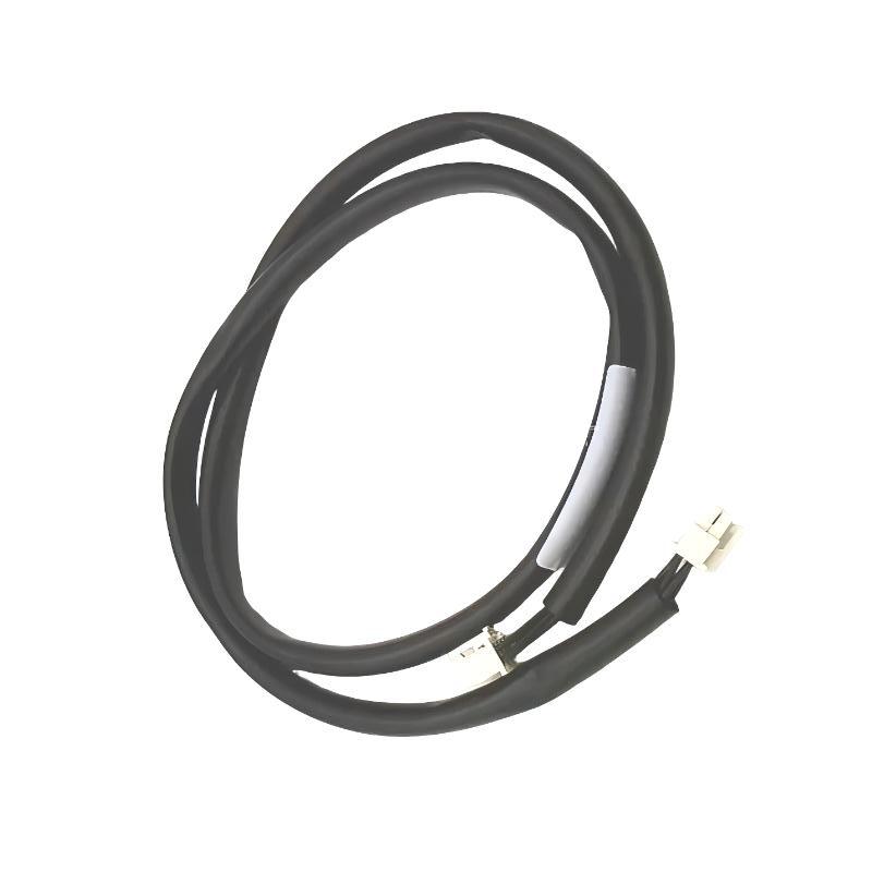
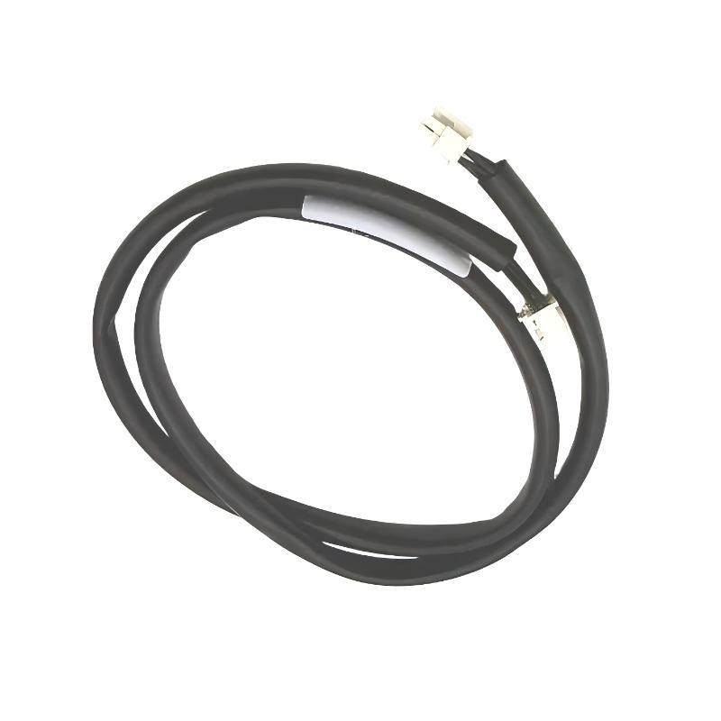
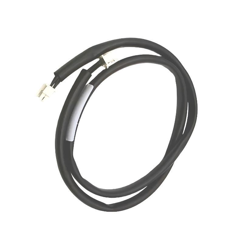
- GE
- IC695CBL002
- Cable
- USA
- 3 feet
- 3 kg
- Xiamen, China
- New & In Stock
- T/T, PayPal, Western Union
- 1 Year
- 1-3 Working Days
- DHL, UPS, TNT, FedEx and EMS.
- 24-Hour Service
- COO
- 47
Our advantage

Global Logistics
We have a 10-year logistics and express cooperation agreement, so our products can be shipped to any place in the world.

Brand new and original
Our products are imported in bulk from the place of origin. Because of the cooperative relationship, our products are all original and 100% new.

24-hour service
We provide 7*24 hours service to our customers. We will be there whenever you need us.

Price advantage
All our products are priced very favorably because we have our own warehouse and supply.
| Company Information | |||
| [email protected] | |||
| Mobile | +8615980777398 | ||
| +8615980777398 | |||
| 15980777398 |
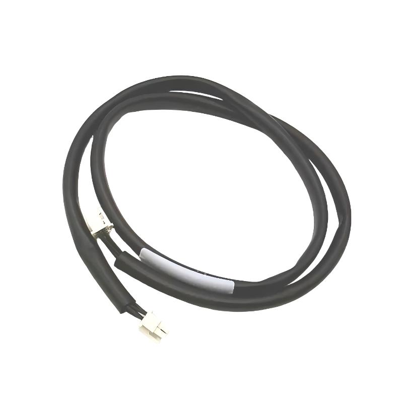
Product Overview
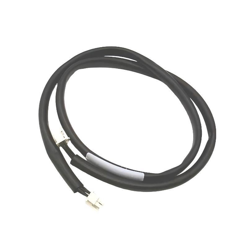
The GE IC695CBL002 is an industrial automation cable intended for use within compatible GE PACSystems RX3i control-system installations. Cables such as this provide the physical electrical connection required for reliable communication or signal exchange between automation components.
Although cables are often considered simple accessories, they can have a direct impact on PLC system availability. Loose connectors, damaged conductors, excessive bending, poor routing, or electromagnetic interference can produce intermittent communication faults that may initially appear to be controller or I/O hardware problems.
The IC695CBL002 has a specified cable length of 3 feet, equivalent to approximately 0.91 meters, making it suitable for short-distance connections inside control cabinets and equipment enclosures. The supplied shipping weight is 3 kg.
For maintenance engineers, the cable should be treated as part of the overall automation communication path rather than as a passive accessory. Correct identification, installation, routing, inspection, and replacement are important for maintaining reliable system operation.
Product Identification
| Parameter | Specification |
|---|---|
| Manufacturer | GE |
| Product Series | PACSystems RX3i |
| Model | IC695CBL002 |
| Product Type | Industrial Automation Cable |
| Primary Function | System Interconnection |
| Cable Length | 3 feet / approximately 0.91 m |
| Shipping Weight | 3 kg |
| Typical Installation | Industrial Control Cabinet |
| Application | PLC System Connection |
| Connection Type | Compatible Industrial Equipment Interface |
| Service Function | Communication / Signal Interconnection |
Technical Specifications
| Technical Item | Specification |
|---|---|
| Product Family | PACSystems RX3i |
| Part Number | IC695CBL002 |
| Cable Category | Industrial Automation Cable |
| Length | 3 ft |
| Approximate Length | 0.91 m |
| Shipping Weight | 3 kg |
| Installation | Cabinet / Equipment Interconnection |
| Application | Industrial Automation |
| Signal Function | System Communication / Connection |
| Construction | Industrial Cable Assembly |
| Maintenance Type | Replaceable Connection Component |
Main Function
The primary purpose of the IC695CBL002 is to provide a reliable electrical connection between compatible automation-system components.
Depending on the system architecture, industrial cables can be used for:
- Controller connections
- I/O system interconnections
- Rack or equipment connections
- Communication interfaces
- System expansion
- Programming and commissioning
- Maintenance connections
- Control-system integration
A typical connection can be represented as:
Automation Controller
↓
IC695CBL002
↓
Compatible System Component
↓
Signal / Data Exchange
↓
Industrial Control Process
The exact equipment connected to the cable should always be confirmed against the applicable system documentation and the connector configuration before installation.
Why Cable Condition Matters
A PLC can be fully operational while a defective cable prevents reliable communication.
Cable-related faults may cause:
- Communication interruptions
- Intermittent data loss
- Diagnostic alarms
- I/O communication problems
- Controller timeouts
- Unexpected equipment behavior
- Difficult-to-reproduce system faults
For this reason, the cable should be included in normal troubleshooting procedures whenever communication between two devices becomes unstable.
Typical Industrial Applications
The GE IC695CBL002 can be used as part of industrial automation installations involving:
- Factory automation
- Machine control
- Process automation
- Power generation
- Water treatment
- Oil and gas
- Chemical processing
- Pharmaceutical manufacturing
- Food and beverage production
- Mining
- Steel manufacturing
- Packaging systems
Its short 3-foot length is particularly useful where connected components are located relatively close to one another inside a cabinet or equipment enclosure.
Installation Guide
1. Confirm the Cable Model
Before installation, verify:
GE IC695CBL002
Do not substitute another cable simply because it has a similar physical appearance. Connector configuration, wiring arrangement, and electrical characteristics must be compatible with the intended system.
2. Inspect the Cable Before Installation
Carefully inspect:
- Cable jacket
- Connector bodies
- Contact pins
- Connector locking mechanism
- Strain-relief areas
- Cable identification
- Signs of bending or crushing
Do not install a cable showing obvious mechanical damage.
3. Confirm Cable Length
The specified cable length is:
3 feet / approximately 0.91 m
Check that the cable can reach both connection points without excessive tension.
A cable should never be stretched to make a connection.
4. Power Down the Equipment
Before connecting or disconnecting the cable:
- Stop the associated equipment.
- Follow the plant shutdown procedure.
- Remove electrical power where required.
- Apply appropriate lockout/tagout procedures.
- Verify that the equipment is safe to service.
5. Identify Both Connection Points
Before connecting the cable, identify:
- Device A
- Device B
- Correct connector
- Correct cable orientation
- Required locking mechanism
Confirm the intended connection against the system wiring documentation.
6. Connect the Cable
Carefully insert each connector.
Verify:
- Correct orientation
- Full insertion
- Secure engagement
- Proper locking
Never force a connector into a mating port.
7. Route the Cable
The 3-foot cable should be routed without:
- Sharp bends
- Excessive tension
- Crushing
- Twisting
- Abrasion
- Contact with moving mechanisms
Keep the cable supported where necessary.
8. Separate From High-Power Wiring
Where practical, route signal and communication cables away from:
- Motor power cables
- Variable-frequency-drive output cables
- Contactors
- Transformers
- High-current conductors
This helps reduce electromagnetic interference.
9. Inspect the Finished Installation
After installation, check:
- Connector engagement
- Cable routing
- Mechanical support
- Clearance from moving equipment
- Separation from power cables
- Absence of excessive tension
10. Restore Power and Test
Restore system power according to the equipment startup procedure.
Check:
- Controller status
- Communication status
- Diagnostic messages
- Connected-device operation
- System alarms
Commissioning Procedure
A basic commissioning sequence should include:
Step 1 — Physical Inspection
Confirm both connectors are correctly installed.
Step 2 — Cable Routing
Verify that the cable is not under tension or exposed to excessive bending.
Step 3 — System Startup
Power the control system according to normal procedures.
Step 4 — Communication Verification
Confirm that connected equipment communicates correctly.
Step 5 — Diagnostic Review
Check the controller for communication or connection alarms.
Step 6 — Operational Test
Operate the connected equipment and monitor communication stability.
Troubleshooting Guide
Fault 1 — No Communication
Possible causes include:
- Cable not connected
- Connector not fully seated
- Incorrect connection point
- Damaged cable
- Connected equipment fault
- Configuration problem
Recommended Checks
- Verify both cable connections.
- Inspect connector condition.
- Check cable routing.
- Test with a known-good compatible cable where appropriate.
- Review controller diagnostics.
Fault 2 — Intermittent Communication
Intermittent faults are commonly associated with physical connection problems.
Possible causes:
- Loose connector
- Damaged connector contacts
- Internal conductor damage
- Excessive vibration
- Cable movement
- Electromagnetic interference
Inspect the cable while monitoring system diagnostics.
Fault 3 — Communication Drops During Machine Operation
If communication is stable while the machine is stopped but fails during operation, investigate:
- Vibration
- Cable movement
- Motor-related interference
- Cable routing
- Connector security
Mechanical movement can expose a marginal connection that appears normal during static inspection.
Fault 4 — Controller Reports Communication Timeout
Possible causes:
- Cable interruption
- Connected device failure
- Connector problem
- Power interruption
- Communication configuration issue
Start troubleshooting at the physical connection before replacing expensive controller hardware.
Fault 5 — Communication Errors Increase When Motors Start
This condition may indicate electromagnetic interference.
Inspect:
- Cable routing
- Separation from motor cables
- Shielding
- Grounding
- VFD installation
- Cabinet wiring practices
Fault 6 — Connector Will Not Seat Properly
Possible causes:
- Incorrect mating connector
- Damaged connector housing
- Bent contact
- Foreign material
- Incorrect orientation
Do not force the connector.
Fault 7 — Cable Jacket Is Damaged
Damage can result from:
- Abrasion
- Crushing
- Excessive bending
- Sharp cabinet edges
- Heat
- Chemical exposure
If internal conductor damage is suspected, replace the cable.
Fault 8 — System Works After Restart but Fails Later
This can indicate an intermittent connection.
Inspect:
- Cable connectors
- Cable movement
- Temperature effects
- Vibration
- Mechanical stress
Intermittent faults should be investigated before they develop into complete communication failures.
Fault 9 — New Cable Does Not Resolve the Problem
If replacing the cable does not correct the problem, investigate:
- Connected device
- Controller configuration
- Power supply
- Communication interface
- Backplane or rack hardware
- Grounding
- System software
Not every communication problem originates in the cable.
Fault 10 — Physical Cable Failure
A cable should be considered defective when there is evidence of:
- Broken conductors
- Severe jacket damage
- Damaged connector
- Bent contacts
- Persistent communication failure
- Intermittent continuity
Replace the cable with a verified compatible unit.
Diagnostic Workflow
A practical troubleshooting sequence is:
Controller
↓
Connector A
↓
IC695CBL002
↓
Connector B
↓
Connected Device
↓
Power Supply
↓
Communication Configuration
↓
System Diagnostics
This approach allows technicians to separate physical connection faults from hardware and software problems.
Preventive Maintenance
Regular inspection can significantly reduce unexpected cable-related failures.
Cable Inspection
Check:
- Jacket condition
- Connector condition
- Strain relief
- Bending
- Abrasion
- Mechanical support
Connector Inspection
Check:
- Contact condition
- Locking mechanism
- Contamination
- Mechanical damage
Routing Inspection
Verify:
- Proper bend radius
- No excessive tension
- No crushing
- Separation from high-power conductors
Environmental Inspection
Check for exposure to:
- Excessive heat
- Moisture
- Oil
- Chemicals
- Dust
- Mechanical vibration
Preventive Maintenance Checklist
| Inspection Item | Recommended Action |
|---|---|
| Cable Jacket | Inspect for cracks and abrasion |
| Connectors | Inspect for damage |
| Contact Pins | Check condition |
| Locking Mechanism | Verify secure engagement |
| Cable Routing | Check for excessive bending |
| Mechanical Support | Verify secure routing |
| Power Cable Separation | Inspect routing |
| Grounding | Verify system grounding |
| Communication Status | Monitor diagnostics |
| Spare Cable | Maintain suitable replacement stock |
Cable Replacement Procedure
When replacing an IC695CBL002, follow the plant’s approved maintenance procedure.
Step 1
Record the existing cable routing and connection points.
Step 2
Shut down the relevant equipment.
Step 3
Remove power where required.
Step 4
Disconnect the existing cable from both devices.
Step 5
Inspect the mating connectors.
Step 6
Install the replacement cable.
Step 7
Confirm both connectors are fully seated.
Step 8
Route and secure the cable correctly.
Step 9
Restore system power.
Step 10
Verify communication.
Step 11
Check controller diagnostics.
Step 12
Perform an operational test.
Key Advantages
- Compact 3-foot cable length
- Suitable for short-distance cabinet connections
- Supports reliable industrial equipment interconnection
- Simple installation and replacement
- Easy visual inspection
- Suitable for PLC and automation environments
- Helps maintain stable system communication
- Appropriate for scheduled preventive maintenance
- Useful as a replacement component for compatible systems
Frequently Asked Questions
What is the GE IC695CBL002?
The GE IC695CBL002 is an industrial automation cable used to establish an electrical connection between compatible system components.
What is the cable length?
The specified cable length is 3 feet, approximately 0.91 meters.
What is the shipping weight?
The specified shipping weight is 3 kg.
Where is the IC695CBL002 typically installed?
Its 3-foot length makes it suitable for short-distance connections inside industrial control cabinets and equipment enclosures.
What causes intermittent communication?
Common causes include loose connectors, damaged conductors, vibration, electromagnetic interference, poor routing, and mechanical stress.
Can a similar-looking cable be used as a replacement?
A replacement should only be used after confirming electrical and connector compatibility. Physical appearance alone is not sufficient to establish compatibility.
How can cable-related faults be diagnosed?
Begin by checking both connectors and the cable’s physical condition. Then inspect routing, grounding, interference sources, controller diagnostics, and the connected devices.
When should the cable be replaced?
Replacement is recommended when the cable has damaged insulation, broken conductors, damaged connectors, bent contacts, or persistent communication problems attributable to the cable.
Conclusion
The GE IC695CBL002 Cable is a compact industrial connection component intended for compatible automation-system installations. Its specified 3-foot (approximately 0.91 m) length makes it suitable for short-distance connections within control cabinets and equipment enclosures, while its stated shipping weight is 3 kg.
Reliable cable installation is an important part of PLC system maintenance. Correct connector engagement, appropriate routing, protection against mechanical damage, separation from high-power wiring, and regular inspection can help prevent intermittent communication problems and unexpected downtime.
When a communication fault occurs, maintenance personnel should inspect the complete signal path rather than immediately replacing the controller or I/O hardware. Checking the IC695CBL002, connectors, connected devices, power supply, grounding, and system diagnostics in sequence provides a practical way to identify faults efficiently and restore stable automation-system operation.