

ProductPRODUCT
Featured products
Contact Us
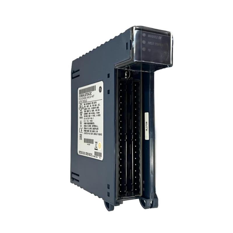
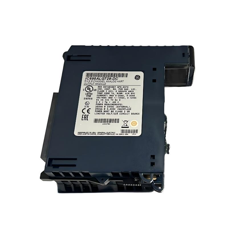
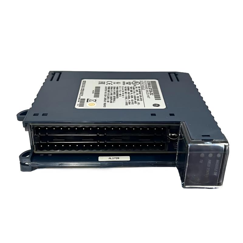
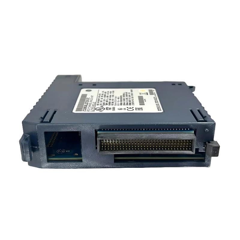
- GE
- IC695ALG728
- RX3i Analog Output Module
- USA
- 145 x 34 x 140 mm
- 0.5 kg
- Xiamen, China
- New & In Stock
- T/T, PayPal, Western Union
- 1 Year
- 1-3 Working Days
- DHL, UPS, TNT, FedEx and EMS.
- 24-Hour Service
- COO
- 62
Our advantage

Global Logistics
We have a 10-year logistics and express cooperation agreement, so our products can be shipped to any place in the world.

Brand new and original
Our products are imported in bulk from the place of origin. Because of the cooperative relationship, our products are all original and 100% new.

24-hour service
We provide 7*24 hours service to our customers. We will be there whenever you need us.

Price advantage
All our products are priced very favorably because we have our own warehouse and supply.
| Company Information | |||
| [email protected] | |||
| Mobile | +8615980777398 | ||
| +8615980777398 | |||
| 15980777398 |
Product Overview
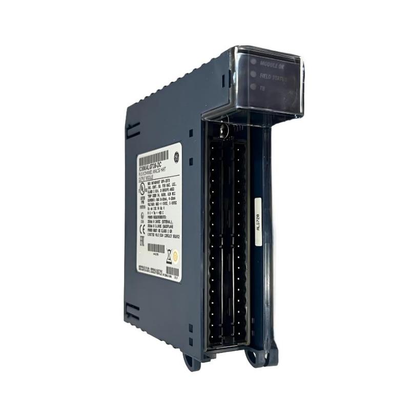
The GE IC695ALG728 is a high-performance RX3i Analog Output Module designed for the GE PACSystems RX3i programmable automation platform. The module converts digital control commands generated by the RX3i CPU into precise analog output signals for controlling industrial field devices. It is widely used in continuous process control applications where accurate analog signal transmission is essential for maintaining stable production processes.
Installed on the RX3i Universal Backplane, the IC695ALG728 communicates with the controller through the high-speed backplane bus, providing reliable and deterministic analog output performance. It is commonly used to control devices such as variable frequency drives (VFDs), control valves, proportional valves, actuators, speed controllers, pressure regulators, and other analog-controlled equipment.
With compact dimensions of 145 × 34 × 140 mm and a shipping weight of approximately 0.5 kg, the module is well suited for high-density control cabinets while maintaining excellent durability in demanding industrial environments.
Designed for continuous industrial operation, the IC695ALG728 combines high output accuracy, fast response time, built-in diagnostics, and excellent electrical noise immunity, making it an ideal solution for modern industrial automation systems.
Product Identification
| Parameter | Specification |
|---|---|
| Manufacturer | GE |
| Product Series | PACSystems RX3i |
| Model | IC695ALG728 |
| Product Type | Analog Output Module |
| Platform | RX3i PLC |
| Primary Function | Analog Signal Output |
| Installation | RX3i Universal Backplane |
| Dimensions | 145 × 34 × 140 mm |
| Weight | 0.5 kg |
| Mounting Method | Rack Installation |
| Communication | RX3i Backplane Bus |
| Cooling | Natural Air Convection |
Technical Specifications
| Technical Item | Specification |
|---|---|
| Product Family | PACSystems RX3i |
| Module Category | Analog Output Module |
| Signal Direction | PLC to Field Device |
| Signal Conversion | Digital to Analog |
| Height | 145 mm |
| Width | 34 mm |
| Depth | 140 mm |
| Weight | Approximately 0.5 kg |
| Installation Platform | RX3i Universal Rack |
| Diagnostics | Module and Channel Diagnostics |
| Isolation | Industrial Grade |
| Operating Mode | Continuous Industrial Service |
Main Functions
The IC695ALG728 converts digital output values calculated by the PLC into analog control signals that regulate industrial equipment.
Typical controlled devices include:
- Variable Frequency Drives (VFDs)
- Motor speed controllers
- Control valves
- Proportional valves
- Hydraulic actuators
- Pneumatic positioners
- Pressure regulators
- Flow control equipment
- Process controllers
- Industrial instrumentation
Control signal flow:
RX3i CPU
↓
PLC Program
↓
IC695ALG728
↓
Analog Output Signal
↓
Field Device
↓
Industrial Process
↓
Feedback System
Working Principle
The PLC continuously executes the control program and calculates the required analog output values.
The module performs the following sequence:
- Receive digital control values from the RX3i CPU.
- Convert digital data into analog electrical signals using high-resolution D/A conversion.
- Output stable analog signals to connected field devices.
- Drive the controlled equipment according to PLC commands.
- Receive process feedback through analog input modules for closed-loop control.
This process enables accurate regulation of speed, flow, pressure, temperature, level, and other continuous process variables.
Typical Industrial Applications
The GE IC695ALG728 is commonly installed in:
- Power generation plants
- Oil & Gas facilities
- Chemical processing
- Water and wastewater treatment
- Food and beverage production
- Pharmaceutical manufacturing
- Steel mills
- Mining operations
- Cement production
- Paper mills
- Marine automation
- General industrial manufacturing
Installation Guide
1. Verify Product Information
Confirm the module identification:
GE IC695ALG728 RX3i Analog Output Module
Ensure the installed module matches the project hardware configuration.
2. Confirm System Compatibility
Verify compatibility with:
- RX3i Universal Backplane
- RX3i CPU
- RX3i Power Supply
- PLC engineering software
- Existing I/O configuration
3. Inspect the Module
Before installation inspect:
- Module housing
- Front label
- Backplane connector
- Terminal interface
- Locking mechanism
- Mechanical condition
Do not install a damaged module.
4. Prepare Cabinet Space
Module dimensions:
- Height: 145 mm
- Width: 34 mm
- Depth: 140 mm
Maintain sufficient clearance for:
- Ventilation
- Wiring access
- Future maintenance
- Module replacement
5. Isolate Power
Before installation:
- Shut down the PLC system.
- Disconnect control power.
- Verify zero voltage.
- Apply lockout/tagout procedures.
6. Install the Module
Insert the module into the designated RX3i rack slot.
Verify:
- Correct alignment
- Complete insertion
- Secure locking
- Proper backplane engagement
7. Connect Output Wiring
Wire the analog output channels according to the approved wiring diagram.
Check:
- Output channel assignment
- Signal polarity
- Shield grounding
- Cable routing
- Terminal identification
Separate analog output wiring from high-voltage power cables to reduce electrical interference.
8. Verify Grounding
Inspect:
- Protective earth
- Signal reference
- Cable shielding
- Ground continuity
Proper grounding ensures stable analog output performance.
9. Configure the Module
Using the engineering software:
- Add the IC695ALG728 to the hardware configuration.
- Configure each analog output channel.
- Select the appropriate output ranges.
- Assign engineering units.
- Configure diagnostics and fail-safe behavior.
10. Commission the System
Restore system power and verify:
- Module status LEDs
- CPU communication
- Output signal values
- Controlled equipment response
- Diagnostic information
Commissioning Procedure
Step 1
Download the hardware configuration.
Step 2
Verify that the controller recognizes the module.
Step 3
Confirm backplane communication.
Step 4
Measure analog output signals using calibrated test equipment.
Step 5
Verify field device response.
Step 6
Test control loops under normal operating conditions.
Troubleshooting Guide
Fault 1 — Module Not Recognized
Possible causes:
- Improper module installation
- Hardware configuration mismatch
- Power supply failure
- Backplane communication issue
- Defective connector
Fault 2 — No Analog Output
Possible causes:
- Incorrect PLC configuration
- Wiring fault
- Output channel disabled
- Field device fault
- No control command
Fault 3 — Incorrect Output Value
Possible causes:
- Incorrect scaling
- Wrong output range
- Programming error
- Wiring error
- Calibration issue
Fault 4 — Output Signal Fluctuation
Possible causes:
- Electrical interference
- Poor grounding
- Loose wiring
- Unstable control algorithm
- Faulty field device
Fault 5 — Controlled Device Does Not Respond
Inspect:
- Output wiring
- Field device power
- Control configuration
- Signal measurement
- Device status
Fault 6 — Multiple Output Channels Fail
Possible causes:
- Power supply problem
- Module failure
- Backplane communication issue
- Hardware configuration error
Fault 7 — Single Output Channel Failure
Check:
- Wiring continuity
- Terminal condition
- Output configuration
- Field device
- Channel diagnostics
Fault 8 — Diagnostic Alarm
Possible causes:
- Internal module fault
- Wiring short circuit
- Configuration mismatch
- Output overload
- Hardware malfunction
Review PLC diagnostics before replacing the module.
Fault 9 — Communication Error
Inspect:
- RX3i CPU
- Rack communication
- Power supply
- Module connector
- Backplane condition
Fault 10 — Unstable Process Control
Possible causes:
- Incorrect analog scaling
- Sensor feedback errors
- Poor controller tuning
- Wiring interference
- Output signal instability
Check the complete control loop before replacing hardware.
Diagnostic Workflow
Follow this troubleshooting sequence:
RX3i CPU
↓
PLC Program
↓
IC695ALG728
↓
Analog Output Wiring
↓
Field Device
↓
Controlled Equipment
↓
Process Feedback
↓
Analog Input Module
This structured diagnostic process helps identify the true source of system faults while avoiding unnecessary component replacement.
Preventive Maintenance
Routine inspections should include:
Mechanical Inspection
- Module housing
- Rack installation
- Locking mechanism
- Connector condition
Electrical Inspection
- Terminal tightness
- Cable insulation
- Ground continuity
- Shield integrity
Software Inspection
- Hardware configuration
- Diagnostic logs
- Alarm history
- Firmware compatibility
Environmental Inspection
- Cabinet temperature
- Ventilation
- Dust accumulation
- Humidity
- Cooling performance
Preventive Maintenance Checklist
| Inspection Item | Recommended Action |
|---|---|
| Module Housing | Visual inspection |
| Backplane Connector | Check condition |
| Output Wiring | Tighten terminals |
| Grounding | Verify continuity |
| Shielding | Inspect cables |
| Diagnostics | Review alarms |
| PLC Backup | Archive project |
| Cabinet Cooling | Clean ventilation |
Replacement Procedure
- Record the rack slot location.
- Back up the PLC project.
- Shut down the PLC.
- Remove system power.
- Disconnect field wiring.
- Remove the existing module.
- Inspect the rack connector.
- Install the replacement IC695ALG728.
- Reconnect field wiring.
- Restore the hardware configuration.
- Apply power.
- Verify communication.
- Measure analog output signals.
- Test connected field devices.
- Return the system to normal operation.
Key Advantages
- High-precision analog output control
- Reliable RX3i backplane communication
- Fast digital-to-analog conversion
- Comprehensive diagnostic capabilities
- Compact rack-mounted design
- Excellent electrical noise immunity
- Easy installation and maintenance
- Long-term operational stability
- Seamless integration with PACSystems RX3i
- Suitable for demanding industrial automation applications
Frequently Asked Questions
What is the GE IC695ALG728?
The GE IC695ALG728 is an RX3i Analog Output Module that converts digital control commands from the PLC into analog output signals for industrial field devices.
What are its dimensions?
145 × 34 × 140 mm
What is its weight?
Approximately 0.5 kg.
Which platform supports this module?
It is designed for the GE PACSystems RX3i automation platform.
What equipment can it control?
It can provide analog output signals to variable frequency drives, control valves, proportional actuators, pressure regulators, flow controllers, and other analog-controlled industrial equipment.
Why is there no analog output signal?
Possible causes include incorrect PLC programming, disabled output channels, wiring faults, field device failures, configuration errors, or module communication problems.
Why is the controlled device unstable?
Instability may result from poor grounding, electrical interference, incorrect analog scaling, loose wiring, improper controller tuning, or faulty field equipment.
What should be checked before replacing the module?
Inspect the PLC program, hardware configuration, output wiring, field devices, power supply, and diagnostic information to ensure the module is the actual source of the fault.
Conclusion
The GE IC695ALG728 RX3i Analog Output Module provides accurate and reliable analog signal generation for demanding industrial automation systems. Measuring 145 × 34 × 140 mm and weighing 0.5 kg, it offers a compact yet powerful solution for controlling a wide range of industrial field devices through the GE PACSystems RX3i platform.
Proper installation, correct wiring, reliable grounding, and accurate configuration are essential for achieving stable analog output performance. Combined with regular preventive maintenance and a structured troubleshooting approach, the IC695ALG728 helps maximize system reliability, improve process control accuracy, reduce unplanned downtime, and support long-term operational efficiency in industrial automation environments.