
NewsNEWCENTER
Featured products

Contact Us
Allen Bradley 1606-XLB240E/A Power Supply Installation Guide
2026-08-24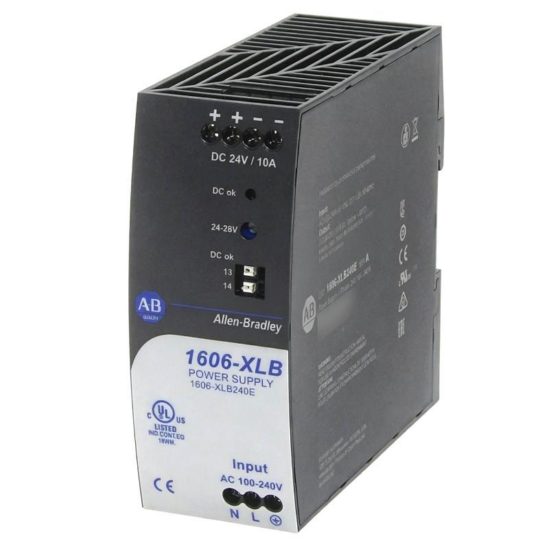
Table of Contents
- Allen Bradley 1606-XLB240E/A Power Supply Installation Overview
- Allen Bradley 1606-XLB240E/A Industrial Power Supply Application
- Allen Bradley 1606-XLB240E/A Installation Planning and Load Review
- Allen Bradley 1606-XLB240E/A Cabinet Mounting and Environmental Checks
- Allen Bradley 1606-XLB240E/A Wiring and DC Power Distribution
- Allen Bradley 1606-XLB240E/A Setup Before Energization
- Allen Bradley 1606-XLB240E/A Commissioning and System Configuration
- Allen Bradley 1606-XLB240E/A Installation Validation
- Allen Bradley 1606-XLB240E/A Field Commissioning Case
- Allen Bradley 1606-XLB240E/A Installation FAQ
- Allen Bradley 1606-XLB240E/A Overall Technical Summary
Allen Bradley 1606-XLB240E/A Power Supply Installation Overview
Allen Bradley 1606-XLB240E/A installation should be approached as a control-power engineering task rather than a simple mounting operation. The most important commissioning checks are correct input wiring, secure DC distribution, appropriate loading, proper grounding, and stable voltage at the equipment actually being powered.
The 1606-XLB240E/A is an Allen Bradley industrial power supply used within automation control systems. Its DC output may support PLC Controllers, I/O Modules, communication interfaces, Sensors, relays, instrumentation, and other control-panel devices. Consequently, poor installation can create symptoms that appear to originate from downstream automation hardware.
A practical Installation Guide therefore needs to verify the complete electrical path from the incoming supply through the power supply and distribution terminals to the final control loads.
Allen Bradley 1606-XLB240E/A Industrial Power Supply Application
In a typical automation cabinet, the power supply forms the electrical foundation for low-voltage control equipment. The quality of this DC bus directly affects the availability of controllers and field interfaces.
The engineering challenge is not only supplying enough current. The distribution arrangement must also prevent excessive voltage drop and minimize the influence of switching loads on sensitive equipment.
Allen Bradley 1606-XLB240E/A Typical Control-System Loads
- PLC Controller and associated control hardware.
- Digital and analog I/O Modules.
- Industrial communication interfaces.
- Sensor and instrumentation circuits.
- Relay and interface circuits.
- Control-panel indication devices.
- Other approved DC automation loads.
When several load categories share one DC bus, the System Configuration should clearly identify critical control circuits and higher-current switching branches. This makes both commissioning and later Fault Diagnosis easier.
Allen Bradley 1606-XLB240E/A Installation Planning and Load Review
Before installing the 1606-XLB240E/A, review the actual load list rather than relying solely on the original cabinet drawing. Automation panels are frequently modified during their service life, and additional I/O Modules, interface relays, or communication equipment may have been added.
The expected continuous load should be calculated first. Then identify loads that operate only during machine startup, actuator movement, or process transitions. These events can produce electrical conditions that are not visible during a simple idle test.
Allen Bradley 1606-XLB240E/A Pre-Installation Review
- Confirm the complete model designation.
- Verify the intended input power arrangement.
- Confirm the DC voltage required by connected equipment.
- Calculate the expected connected load.
- Identify high-current or switching loads.
- Review conductor sizing and expected voltage drop.
- Check protective devices.
- Review cabinet ventilation and ambient conditions.
Allen Bradley 1606-XLB240E/A Cabinet Mounting and Environmental Checks
The mounting position should provide sufficient clearance for heat dissipation and access to the wiring terminals. Avoid placing the power supply where neighboring equipment can obstruct its ventilation path.
Thermal conditions deserve attention during industrial commissioning because cabinet temperature can be considerably higher than room temperature. A power supply that operates normally during a short test may behave differently after the cabinet reaches its normal operating temperature.
Mechanical installation should also account for vibration. Cabinets installed close to motors, pumps, compressors, or other vibrating machinery should be inspected periodically for terminal loosening and conductor movement.
Allen Bradley 1606-XLB240E/A Wiring and DC Power Distribution
Allen Bradley 1606-XLB240E/A wiring should be performed with the relevant electrical source isolated and in accordance with the approved site safety procedure. Input conductors, DC output conductors, and protective-earth connections must be identified from the product markings and electrical documentation.
Never determine DC polarity from conductor color alone. Trace the positive and negative circuits against the panel drawing and verify the connections before energizing sensitive PLC or Module equipment.
Allen Bradley 1606-XLB240E/A Wiring Practices
- Use conductors appropriate for the expected current and installation method.
- Keep terminals mechanically secure.
- Maintain clear separation between power and sensitive signal wiring where appropriate.
- Verify DC polarity before connecting downstream equipment.
- Provide suitable branch protection.
- Label distribution branches clearly.
- Inspect wiring for damaged insulation or exposed conductors.
After termination, perform a point-to-point inspection. Pay particular attention to common DC returns, branch connections, field modifications, and unused conductors that may have been incorrectly connected.
Allen Bradley 1606-XLB240E/A Setup Before Energization
The 1606-XLB240E/A Setup should begin with a controlled verification of the input circuit and then progress toward the DC load. Before connecting the complete automation system, confirm that the supply is correctly installed and that the output circuit is free from unintended connections.
Allen Bradley 1606-XLB240E/A setup sequence:

INPUT CHECK
  Verify source
  Verify protection
  Verify conductor connections

POWER SUPPLY CHECK
  Energize according to the approved procedure
  Measure DC output
  Record the baseline

DISTRIBUTION CHECK
  Measure the main DC bus
  Compare with the supply terminal reading

LOAD CHECK
  Energize critical PLC equipment
  Add remaining branches progressively
  Monitor voltage during switching events
The purpose of staged Setup is to identify abnormal behavior early. If a voltage change appears immediately after a particular branch is connected, that branch should be investigated before continuing with full Commissioning.
Allen Bradley 1606-XLB240E/A Commissioning and System Configuration
Commissioning should prove that the 1606-XLB240E/A operates correctly within the intended System Configuration. The PLC Controller should start normally, I/O Modules should remain available, and communication interfaces should not reset unexpectedly during representative machine operation.
Where possible, introduce the loads in groups. This provides a practical reference for identifying the electrical effect of each branch.
Allen Bradley 1606-XLB240E/A Commissioning Checks
- Record the incoming voltage.
- Record the DC output voltage at the power supply.
- Measure the main DC distribution voltage.
- Measure voltage at important remote loads.
- Start the PLC Controller.
- Verify I/O Module status.
- Check communication stability.
- Operate representative switching loads.
- Repeat measurements after the cabinet reaches normal temperature.
Commissioning should also include the machine conditions most likely to stress the control-power system, such as simultaneous relay operation, actuator startup, or transition from manual to automatic control.
Allen Bradley 1606-XLB240E/A Installation Validation
A successful installation is not demonstrated simply because the 1606-XLB240E/A produces a normal voltage at its own terminals. The final validation should include downstream measurement because cable resistance and connection quality can affect the voltage available to remote equipment.
For example, if the supply output remains close to its nominal DC level but a remote I/O distribution point falls significantly during a switching event, the distribution circuit should be investigated before identifying the power supply as the fault source.
Allen Bradley 1606-XLB240E/A Acceptance Data
- Incoming supply measurement.
- Power-supply output measurement.
- Main DC bus measurement.
- Remote load measurement.
- PLC Controller operating status.
- I/O Module operating status.
- Communication status.
- DC voltage response during load switching.
Allen Bradley 1606-XLB240E/A Field Commissioning Case
In one commissioning case, an Allen Bradley control cabinet used the 1606-XLB240E/A to supply a PLC Controller, remote I/O, and several interface circuits. The initial DC measurement at the power-supply terminals was approximately 24 VDC, and the controller completed startup normally.
During the automatic-cycle test, however, a remote I/O section intermittently lost communication when several actuator interface circuits switched at the same time.
The engineer first checked the 1606-XLB240E/A output during the event rather than replacing it. The source voltage remained relatively stable. A second measurement at the remote distribution point showed a temporary reduction to approximately 22.6 VDC.
This measurement changed the diagnostic direction. The power supply was delivering a stable source voltage, so attention moved to the distribution branch. Inspection found a high-resistance terminal connection that had not produced an obvious symptom during the low-current standby condition.
After correcting the connection, the automatic-cycle test was repeated. The remote I/O remained online and the original communication interruption could not be reproduced.
The practical lesson is important for both Installation and Troubleshooting: source-side voltage alone does not prove that every downstream automation device is receiving stable power.
Allen Bradley 1606-XLB240E/A Installation FAQ
What should be checked before installing the Allen Bradley 1606-XLB240E/A?
Verify the model, input power arrangement, required DC voltage, connected load, protective devices, conductor sizing, cabinet environment, grounding arrangement, and downstream System Configuration.
Why should the DC voltage be measured at the remote load?
A long cable run or high-resistance connection can produce voltage drop between the power supply and the equipment. A measurement at the supply cannot reveal every distribution problem.
Can a power supply installation problem cause PLC communication faults?
Yes. A temporary DC disturbance can reset a PLC Controller, remote I/O Module, or communication interface. The automation system may then report the resulting communication loss rather than the original power disturbance.
What is a practical Allen Bradley 1606-XLB240E/A Commissioning method?
Verify the input circuit, establish the supply output baseline, check the main DC bus, energize critical control equipment, add additional branches progressively, and test the system under representative operating conditions.
What commissioning information is useful for future Troubleshooting?
Record normal input and output voltage, important load-side measurements, connected load conditions, PLC status, I/O status, communication behavior, and any voltage changes observed during switching events.
Allen Bradley 1606-XLB240E/A Overall Technical Summary
The Allen Bradley 1606-XLB240E/A should be installed and commissioned as part of the complete industrial control-power system. Correct wiring, protection, cabinet layout, thermal planning, load assessment, and DC distribution provide the foundation, while measurement-based Commissioning confirms actual operating performance.
For field engineers, comparing the power-supply output with voltage at critical downstream loads is especially valuable. This approach can identify distribution resistance, loose connections, and branch-loading problems that might otherwise be mistaken for PLC, Module, Sensor, or communication failures.
Once the 1606-XLB240E/A has passed staged Setup, load validation, and representative machine testing, the recorded measurements should be retained as a baseline for future maintenance, Troubleshooting, and Fault Diagnosis.