

ProductPRODUCT
Featured products
Contact Us
- Siemens
- 6AG1134-6FF00-2AA1
- Analog Input Module
- Germany
- 15 × 73 × 58 mm
- 0.031 kg
- Xiamen, China
- New & In Stock
- T/T, PayPal, Western Union
- 1 Year
- 1-3 Working Days
- DHL, UPS, TNT, FedEx and EMS.
- 24-Hour Service
- COO
- 51
Our advantage

Global Logistics
We have a 10-year logistics and express cooperation agreement, so our products can be shipped to any place in the world.

Brand new and original
Our products are imported in bulk from the place of origin. Because of the cooperative relationship, our products are all original and 100% new.

24-hour service
We provide 7*24 hours service to our customers. We will be there whenever you need us.

Price advantage
All our products are priced very favorably because we have our own warehouse and supply.
| Company Information | |||
| [email protected] | |||
| Mobile | +8615980777398 | ||
| +8615980777398 | |||
| 15980777398 |
Product Overview
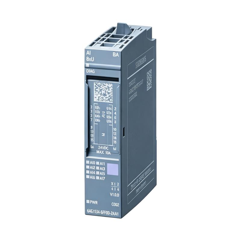
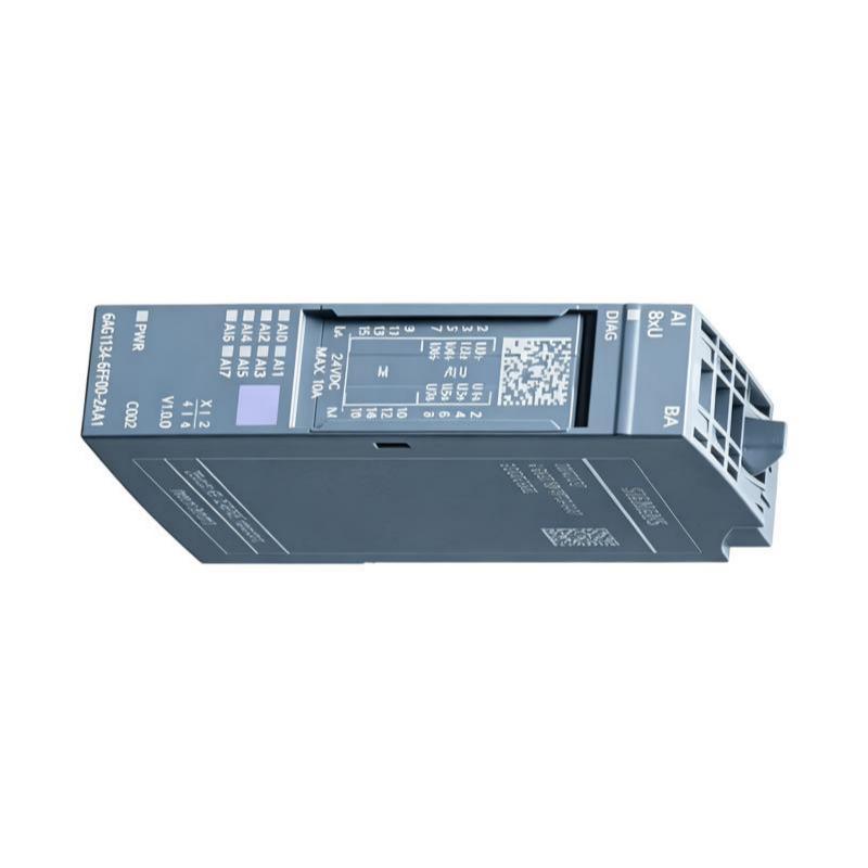
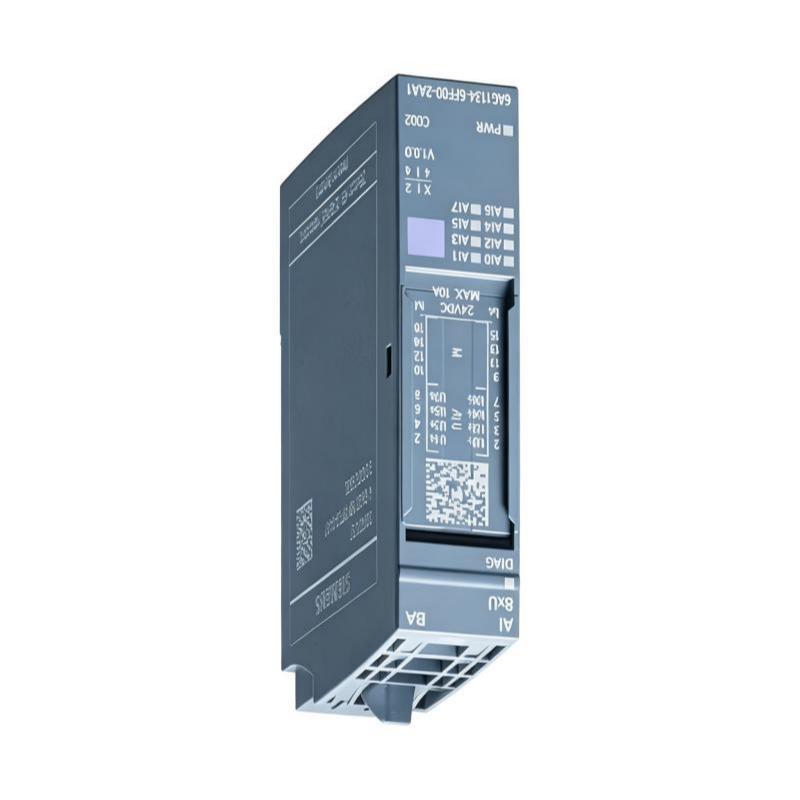
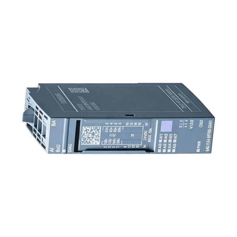
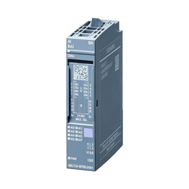
The Siemens 6AG1134-6FF00-2AA1 is a SIPLUS ET 200SP Analog Input Module designed for reliable analog signal acquisition in distributed industrial automation systems. Based on the Siemens ET 200SP platform, this module is engineered to convert analog process signals from field devices into digital values that can be processed by SIMATIC PLC controllers.
As a SIPLUS version, the 6AG1134-6FF00-2AA1 incorporates an industrial-grade conformal coating that provides enhanced resistance to humidity, condensation, corrosive gases, dust, and other harsh environmental conditions. This makes the module particularly suitable for demanding industries such as power generation, chemical processing, oil and gas, water treatment, mining, metallurgy, and manufacturing.
The module features a compact mechanical design measuring 15 × 73 × 58 mm with a lightweight construction of approximately 0.031 kg, allowing high-density installation inside ET 200SP distributed I/O stations while minimizing cabinet space requirements.
Designed for continuous industrial operation, the module delivers stable analog signal processing, comprehensive diagnostics, and seamless integration with Siemens SIMATIC automation systems.
Product Identification
| Parameter | Specification |
|---|---|
| Manufacturer | Siemens |
| Product Series | SIPLUS ET 200SP |
| Model | 6AG1134-6FF00-2AA1 |
| Product Type | Analog Input Module |
| System Platform | ET 200SP |
| Installation | Distributed I/O Station |
| Function | Analog Signal Acquisition |
| Dimensions | 15 × 73 × 58 mm |
| Weight | 0.031 kg |
| Housing Width | 15 mm |
| Mounting | DIN Rail |
| Environmental Design | SIPLUS Conformal Coating |
Technical Specifications
| Technical Item | Specification |
|---|---|
| Product Family | SIPLUS ET 200SP |
| Product Category | Analog Input Module |
| Installation System | ET 200SP |
| Mechanical Width | 15 mm |
| Height | 73 mm |
| Depth | 58 mm |
| Weight | Approximately 0.031 kg |
| Mounting Method | DIN Rail |
| Cooling | Natural Convection |
| Protection | Industrial Environment |
| Signal Processing | Analog-to-Digital Conversion |
| Communication | ET 200SP Backplane |
Main Functions
The Siemens 6AG1134-6FF00-2AA1 receives analog signals from industrial field instruments and converts them into digital process values for PLC processing.
Typical connected devices include:
- Pressure transmitters
- Temperature transmitters
- Flow transmitters
- Level sensors
- Position sensors
- Process analyzers
- Monitoring equipment
- Industrial instrumentation
Signal path:
Field Instrument
↓
Analog Signal
↓
6AG1134-6FF00-2AA1
↓
ET 200SP Backplane
↓
SIMATIC PLC
↓
Control Program
↓
HMI / SCADA
↓
Industrial Process
Working Principle
The analog input module continuously samples electrical signals generated by field devices.
The conversion process consists of:
- Sensor measures the physical variable.
- Transmitter generates an analog electrical signal.
- The analog signal enters the module.
- Internal A/D conversion converts the signal into digital values.
- Digital data is transferred to the PLC.
- PLC software scales the raw value.
- Engineering values become available for monitoring and control.
Reliable measurement depends on proper installation, wiring, configuration, and calibration.
Typical Industrial Applications
The module is suitable for:
- Process automation
- Chemical plants
- Oil & Gas
- Water treatment
- Power generation
- Pharmaceutical manufacturing
- Food & Beverage
- Steel industry
- Cement production
- Mining
- Building automation
- Energy management
Installation Guide
1. Verify Product Information
Confirm the complete model number:
Siemens 6AG1134-6FF00-2AA1
Do not substitute another analog input module solely because it has similar dimensions.
2. Verify System Compatibility
Ensure compatibility with:
- Siemens ET 200SP station
- BaseUnit
- Interface module
- SIMATIC PLC
- Engineering software
- Hardware configuration
3. Inspect the Module
Before installation check:
- Housing
- Connector
- Contact pins
- Locking mechanism
- Conformal coating
- Physical damage
Replace any damaged module before commissioning.
4. Prepare Installation Location
Module dimensions:
- Width: 15 mm
- Height: 73 mm
- Depth: 58 mm
Ensure sufficient space for:
- Ventilation
- Wiring
- Maintenance
- Future expansion
5. Verify Cabinet Conditions
Confirm:
- Clean environment
- Proper temperature
- Acceptable humidity
- Adequate grounding
- Stable power supply
- Limited vibration
6. Isolate Electrical Power
Before installation:
- Stop production
- Remove power
- Lock out energy sources
- Verify zero voltage
7. Install the Module
Mount the module on the ET 200SP BaseUnit.
Verify:
- Proper alignment
- Correct slot
- Full engagement
- Secure locking
8. Connect Field Wiring
Follow approved electrical drawings.
Verify:
- Terminal numbers
- Channel assignment
- Signal polarity
- Shield grounding
- Cable identification
9. Separate Signal Wiring
Avoid routing analog cables alongside:
- Motor cables
- VFD output wiring
- High-current conductors
- Switching circuits
Proper cable routing minimizes electromagnetic interference.
10. Grounding
Ensure proper grounding of:
- Cabinet
- Shield
- Power supply
- Signal reference
Incorrect grounding can cause unstable measurements.
Configuration Procedure
Step 1
Configure the module within STEP 7 or TIA Portal.
Step 2
Configure each analog input channel.
Verify:
- Signal type
- Measurement range
- Diagnostic parameters
- Filter settings
Step 3
Download the hardware configuration.
Step 4
Power the ET 200SP station.
Verify:
- Communication
- Diagnostics
- LED status
Step 5
Observe raw analog values.
Compare readings with:
- Field instruments
- Calibrators
- Process measurements
Step 6
Verify engineering scaling.
Confirm:
- Raw values
- Engineering units
- Alarm limits
- HMI display
Step 7
Perform operational testing.
Verify:
- PLC logic
- Alarm functions
- Control response
- SCADA display
Troubleshooting Guide
Fault 1 — Module Not Detected
Possible causes:
- Incorrect configuration
- BaseUnit installation error
- Power failure
- Communication problem
Inspection path:
Hardware Configuration
↓
BaseUnit
↓
6AG1134-6FF00-2AA1
↓
PLC Diagnostics
Fault 2 — Analog Reading Always Zero
Possible causes:
- Broken wiring
- Failed transmitter
- Wrong configuration
- Missing sensor power
Fault 3 — Reading Too High
Inspect:
- Signal range
- Sensor output
- Wiring
- Scaling
- Grounding
Fault 4 — Reading Too Low
Possible causes:
- Signal attenuation
- Loose wiring
- Incorrect scaling
- Sensor degradation
Fault 5 — Measurement Fluctuation
Possible causes:
- Electrical noise
- Poor grounding
- Damaged cable
- Loose terminals
- Nearby VFD
Fault 6 — Multiple Channels Fail
Inspect:
- Common power supply
- BaseUnit
- Configuration
- PLC diagnostics
Fault 7 — Single Channel Failure
Check:
- Sensor
- Wiring
- Channel configuration
- Terminal
- PLC address
Fault 8 — Incorrect HMI Value
Possible causes:
- PLC scaling
- Incorrect engineering units
- Wrong HMI tag
- Program logic
Fault 9 — Communication Error
Inspect:
- ET 200SP interface
- Bus communication
- Hardware diagnostics
- PLC status
Fault 10 — Intermittent Signal
Possible causes:
- Loose connector
- Moisture
- Vibration
- Shielding failure
- Damaged cable
Diagnostic Workflow
Recommended inspection order:
Sensor
↓
Transmitter
↓
Signal Cable
↓
BaseUnit
↓
6AG1134-6FF00-2AA1
↓
ET 200SP
↓
PLC
↓
Scaling
↓
HMI
This systematic approach minimizes troubleshooting time and unnecessary component replacement.
Preventive Maintenance
Routine inspections should include:
Mechanical Inspection
- Housing
- Connectors
- Locking mechanism
- Module installation
Wiring Inspection
Check:
- Cable insulation
- Terminal tightness
- Shield continuity
- Wire identification
Electrical Inspection
Verify:
- Supply voltage
- Grounding
- Shielding
- Cabinet power quality
Software Inspection
Review:
- Diagnostics
- Alarm history
- Hardware configuration
- Scaling parameters
Environmental Inspection
Monitor:
- Cabinet temperature
- Humidity
- Dust
- Corrosive atmosphere
- Ventilation
Preventive Maintenance Checklist
| Inspection Item | Recommended Action |
|---|---|
| Module Housing | Visual inspection |
| Wiring | Tighten terminals |
| Grounding | Verify continuity |
| Shielding | Inspect cable shields |
| Diagnostics | Review alarms |
| Hardware Configuration | Verify parameters |
| PLC Backup | Archive project |
| Cabinet | Clean and inspect ventilation |
Replacement Procedure
- Record module position.
- Back up the PLC project.
- Disconnect power.
- Remove field wiring.
- Remove the old module.
- Inspect the BaseUnit.
- Install the replacement module.
- Reconnect wiring.
- Download hardware configuration.
- Restore power.
- Verify diagnostics.
- Confirm analog measurements.
- Test HMI indications.
- Return equipment to service.
Advantages
- Compact 15 mm installation width
- Lightweight 0.031 kg design
- SIPLUS conformal coating
- Designed for ET 200SP distributed I/O
- High reliability in harsh environments
- Excellent integration with SIMATIC PLC systems
- Easy maintenance
- High-density cabinet installation
- Stable analog signal acquisition
- Long service life
Frequently Asked Questions
What is the Siemens 6AG1134-6FF00-2AA1?
It is a SIPLUS ET 200SP analog input module designed for acquiring analog process signals in Siemens distributed automation systems.
What are the dimensions?
15 × 73 × 58 mm
What is the weight?
Approximately 0.031 kg.
What is its primary function?
To convert analog field signals into digital data that can be processed by a Siemens PLC.
Which systems support this module?
It is designed for Siemens ET 200SP distributed I/O systems using compatible BaseUnits and SIMATIC controllers.
Why are analog values unstable?
Typical causes include electrical interference, poor shielding, incorrect grounding, loose wiring, or unstable field devices.
Why is the HMI reading incorrect?
Incorrect PLC scaling, engineering unit configuration, HMI tag assignment, or application programming should be checked before replacing hardware.
What should be verified before replacing the module?
Inspect field devices, signal wiring, BaseUnit connections, power supply, hardware configuration, and diagnostic information to ensure the module is the actual source of the fault.
Is preventive maintenance necessary?
Yes. Periodic inspection of wiring, cabinet conditions, grounding, diagnostics, and hardware configuration helps maximize long-term reliability.
Conclusion
The Siemens 6AG1134-6FF00-2AA1 Analog Input Module is a compact SIPLUS ET 200SP component designed for dependable analog signal acquisition in modern distributed automation systems. Its 15 × 73 × 58 mm dimensions and 0.031 kg weight make it ideal for high-density installations while maintaining excellent environmental durability through its SIPLUS protective design.
Reliable performance depends on correct hardware selection, proper installation on the ET 200SP BaseUnit, accurate field wiring, appropriate PLC configuration, and regular preventive maintenance. During troubleshooting, engineers should always follow the complete signal path—from the field instrument through the module, PLC, and HMI—to identify the root cause efficiently and avoid unnecessary hardware replacement.
With proper engineering practices, the 6AG1134-6FF00-2AA1 provides long-term stable analog data acquisition for industrial process control, machine automation, and critical monitoring applications.