

ProductPRODUCT
Featured products
Contact Us
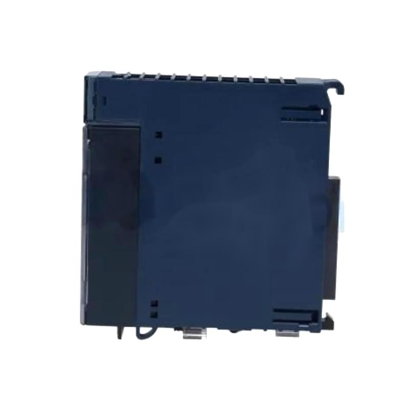
- GE
- IC695ALG508
- RX3i Analog Input Module
- USA
- 145 x 34 x 140 mm
- 0.41 kg
- Xiamen, China
- New & In Stock
- T/T, PayPal, Western Union
- 1 Year
- 1-3 Working Days
- DHL, UPS, TNT, FedEx and EMS.
- 24-Hour Service
- COO
- 7
Our advantage

Global Logistics
We have a 10-year logistics and express cooperation agreement, so our products can be shipped to any place in the world.

Brand new and original
Our products are imported in bulk from the place of origin. Because of the cooperative relationship, our products are all original and 100% new.

24-hour service
We provide 7*24 hours service to our customers. We will be there whenever you need us.

Price advantage
All our products are priced very favorably because we have our own warehouse and supply.
| Company Information | |||
| [email protected] | |||
| Mobile | +8615980777398 | ||
| +8615980777398 | |||
| 15980777398 |
Product Overview
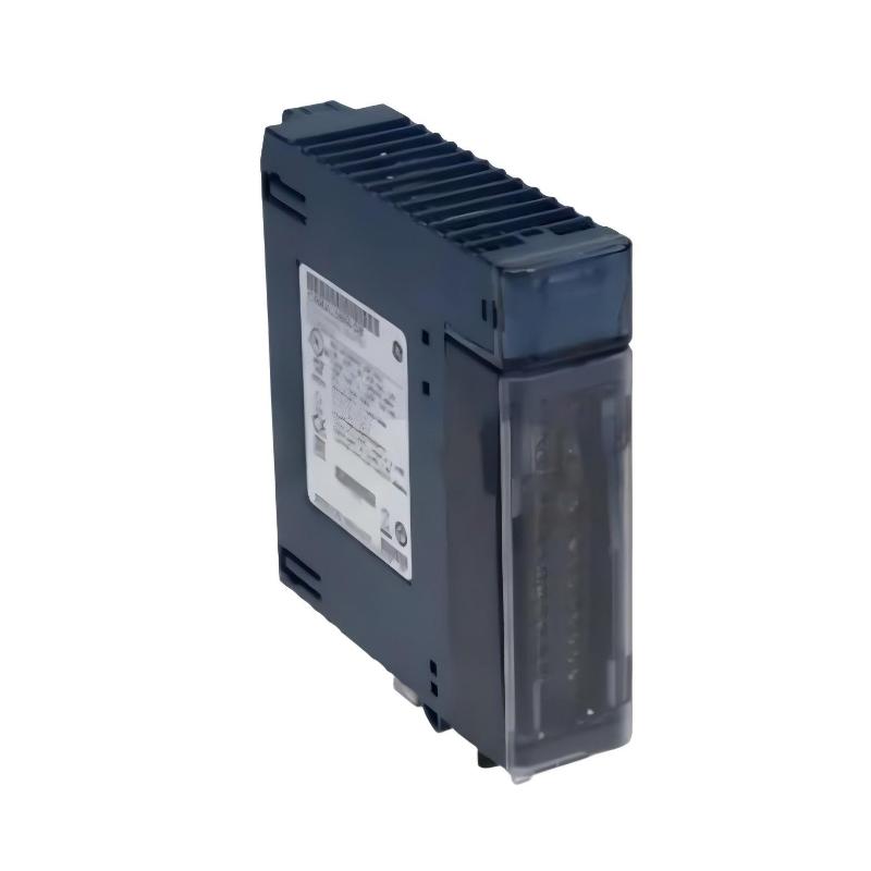
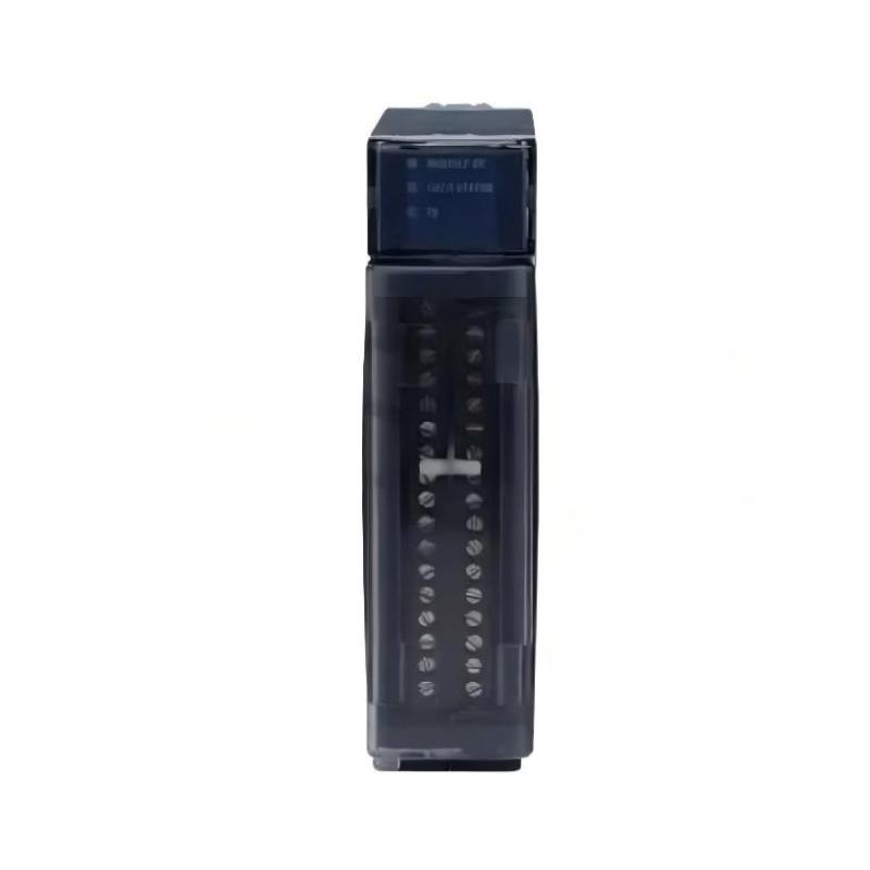
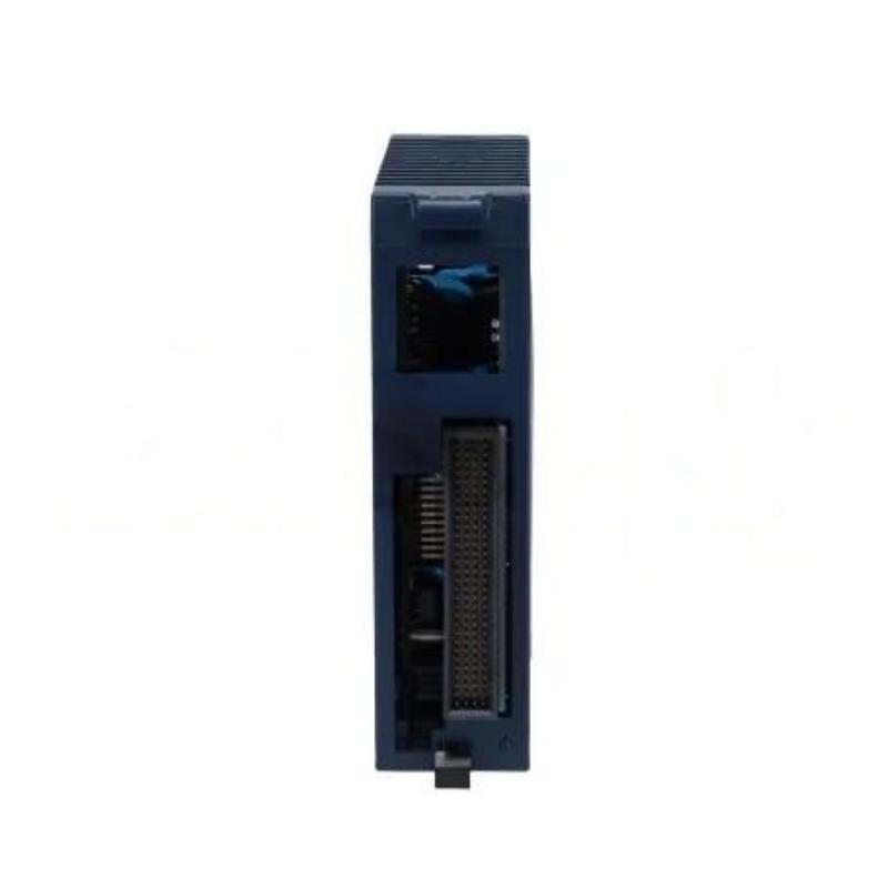
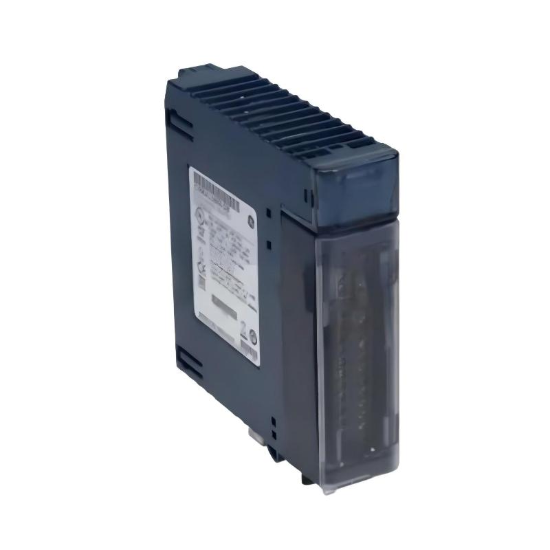
The GE IC695ALG508 RX3i Analog Input Module is an industrial automation analog input component used within compatible GE RX3i PLC architectures. It provides an interface between analog field instrumentation and the controller, allowing continuously varying process signals to be acquired and processed by the PLC.
Analog input modules are commonly used in applications where process variables cannot be represented simply as ON/OFF states. Depending on the application and configured field instrumentation, analog measurements may include pressure, temperature, flow, level, position, speed, current, voltage, and other continuously changing process parameters.
The specified dimensions of the GE IC695ALG508 are 145 × 34 × 140 mm, while the specified weight is 0.41 kg.
Correct installation requires more than simply inserting the module into the PLC rack. Technicians should verify system compatibility, field signal characteristics, wiring, grounding, shielding, hardware configuration, channel settings, and scaling before putting the system into production.
Product Identification
| Parameter | Specification |
|---|---|
| Manufacturer | GE |
| Product Family | RX3i |
| Model | IC695ALG508 |
| Product Type | RX3i Analog Input Module |
| Main Function | Analog Signal Acquisition |
| Application | Industrial Automation / PLC |
| Dimensions | 145 × 34 × 140 mm |
| Weight | 0.41 kg |
| Installation | RX3i Control System |
| System Role | Analog Field Signal Interface |
| Maintenance Focus | Signal Integrity, Wiring, Configuration |
Technical Specifications
| Technical Item | Specification |
|---|---|
| Manufacturer | GE |
| Series | RX3i |
| Model | IC695ALG508 |
| Product Category | Analog Input Module |
| Primary Function | Analog Input Acquisition |
| Dimensions | 145 × 34 × 140 mm |
| Weight | 0.41 kg |
| Application | Industrial Control |
| Installation Environment | Industrial Control Cabinet |
| System Integration | RX3i PLC Architecture |
| Signal Processing | Analog-to-Digital Input Acquisition |
| Configuration | Application Dependent |
| Maintenance | Signal, Wiring and Diagnostic Inspection |
The exact input channel arrangement, supported signal ranges, resolution, isolation characteristics, terminal assignment, electrical limits, and configuration parameters should be confirmed against the applicable system documentation before commissioning.
What Is the GE IC695ALG508?
The IC695ALG508 is identified as an RX3i Analog Input Module.
Its primary role within an automation system is to acquire analog information from field devices and make that information available to the PLC control program.
A typical signal path can be represented as:
Process Variable
↓
Sensor / Transmitter
↓
Analog Signal
↓
IC695ALG508
↓
RX3i Backplane
↓
RX3i CPU
↓
Control Program
↓
HMI / SCADA / Control Outputs
This architecture allows continuously changing physical measurements to be used by industrial control logic.
Function of an Analog Input Module
Industrial sensors and transmitters often represent physical measurements using electrical signals. The analog input module receives these signals and converts the electrical information into digital data that the PLC can process.
The controller can then use the acquired data for:
- Process monitoring
- Alarm generation
- Automatic control
- PID functions
- Equipment protection
- Data logging
- HMI visualization
- Production management
The quality of the final measurement depends on the entire signal chain rather than the analog module alone.
Typical Measurement Architecture
A typical installation follows this structure:
Field Measurement
→
Transmitter
→
Signal Wiring
→
IC695ALG508
→
PLC Data
→
Scaling
→
Engineering Units
→
Control / Monitoring
For example, a pressure transmitter may produce an analog signal proportional to pressure. The IC695ALG508 acquires that signal, and the PLC program converts the corresponding raw value into a pressure value used by the control application.
Installation Guide
1. Verify the Model
Before installation, verify the module identification:
GE IC695ALG508
Compare the model with the PLC hardware configuration and system documentation.
Physical similarity between two modules does not guarantee electrical or software compatibility.
2. Inspect the Module
Before installation, check the module for:
- Cracked enclosure
- Damaged terminals
- Bent contacts
- Corrosion
- Contamination
- Signs of overheating
- Mechanical deformation
Do not install a module showing significant physical damage.
3. Confirm System Compatibility
Verify:
- RX3i compatibility
- CPU configuration
- Rack or backplane arrangement
- Field signal requirements
- Input range
- Wiring requirements
- Software configuration
- Application scaling
The analog module, field transmitter, and PLC configuration must be treated as one complete system.
4. Check Physical Dimensions
The specified dimensions are:
145 × 34 × 140 mm
Allow sufficient space for:
- Installation
- Terminal access
- Wiring
- Inspection
- Maintenance
- Ventilation
Avoid placing the module where adjacent cables or equipment can interfere with installation or cooling.
5. Check Module Weight
The specified weight is:
0.41 kg
Ensure that the mounting arrangement securely supports the module and associated field wiring.
6. Prepare the Cabinet
Before installation:
- Inspect the mounting location.
- Check adjacent modules.
- Verify cabinet cleanliness.
- Confirm ventilation.
- Review grounding.
- Plan signal cable routing.
Analog signals are susceptible to interference, so wiring layout should be considered before the system is energized.
7. Shut Down and Isolate Power
Before installing or removing the module:
- Stop the controlled process.
- Put the machine into a safe state.
- Shut down the PLC system.
- Isolate the applicable electrical power.
- Apply lockout/tagout procedures where required.
- Verify that hazardous voltage has been removed.
- Follow the applicable discharge and safety requirements.
Never assume that a stopped PLC means all associated circuits are electrically safe.
8. Install the Module
Position the IC695ALG508 correctly in the designated RX3i system location.
Check:
- Orientation
- Mechanical seating
- Backplane engagement
- Mounting security
- Clearance from adjacent components
Do not use excessive force.
9. Connect Field Signals
Connect field instrumentation according to the approved system wiring diagram.
Pay attention to:
- Channel assignment
- Signal polarity
- Signal common
- Shielding
- Grounding
- Cable routing
An incorrectly connected analog signal can produce a measurement that looks plausible but is inaccurate.
10. Route Analog Cables Correctly
Where possible, separate analog signal cables from:
- Motor power cables
- VFD cables
- Contactor wiring
- High-current conductors
- Switching circuits
This reduces the possibility of induced electrical noise.
11. Verify Shielding and Grounding
Follow the control-system grounding strategy for shielded instrumentation cables.
Improper grounding can result in:
- Signal noise
- Offset
- Measurement instability
- Ground loops
Shield termination should follow the engineering design rather than being applied identically to every installation.
Configuration and Commissioning
Step 1 – Verify Hardware Configuration
Confirm that the PLC project identifies the IC695ALG508 in the correct system position.
A hardware configuration mismatch can cause a properly installed module to appear unavailable or generate diagnostics.
Step 2 – Configure the Input
Configure each channel according to the connected field instrument.
Check the applicable:
- Input mode
- Signal range
- Channel enablement
- Diagnostic settings
- Engineering range
- Scaling parameters
Step 3 – Verify the Field Transmitter
Before diagnosing the analog input module, confirm that the transmitter itself is operating correctly.
Check:
- Transmitter power
- Output configuration
- Process conditions
- Signal wiring
- Signal polarity
Step 4 – Observe Raw Input Data
Monitor the raw input value in the PLC.
Compare the PLC reading with the expected signal from the transmitter.
If the raw input is wrong, investigate the field signal path first.
Step 5 – Verify Scaling
The raw PLC value normally needs to be converted into engineering units.
A simplified relationship is:
Raw Input → Input Range → Engineering Range → Process Value
Incorrect scaling can cause a correct electrical signal to appear as an incorrect process measurement.
Step 6 – Compare With a Reference
Where practical, compare the PLC value with an independent calibrated instrument.
This can help distinguish between:
- Sensor errors
- Transmitter errors
- Wiring problems
- Module problems
- Scaling errors
Step 7 – Test Alarm Functions
Verify the configured alarm thresholds.
Depending on the application, test:
- Low alarm
- High alarm
- Low-low alarm
- High-high alarm
Confirm that the control program responds correctly.
Step 8 – Verify HMI / SCADA Values
Check the displayed value on connected supervisory systems.
Verify:
- Engineering units
- Scaling
- Decimal position
- Alarm status
- Trend behavior
Troubleshooting Guide
Fault 1 – Analog Input Reads Zero
Possible Causes
- Open circuit
- Incorrect wiring
- Failed transmitter
- Incorrect channel configuration
- Missing transmitter power
- Terminal problem
- Incorrect signal type
Diagnostic Sequence
Check:
Transmitter → Wiring → Terminal → IC695ALG508 → PLC Raw Data → Scaling
This sequence helps identify whether the problem is in the field or control system.
Fault 2 – Analog Reading Is Too High
Possible causes include:
- Incorrect scaling
- Incorrect input configuration
- Excessive signal
- Wiring error
- Grounding issue
- Electrical interference
- Transmitter configuration problem
First determine whether the raw value is high or whether only the scaled engineering value is high.
Fault 3 – Analog Reading Is Too Low
Potential causes include:
- Weak transmitter output
- Incorrect scaling
- Wiring resistance
- Incorrect configuration
- Poor terminal contact
- Signal-reference problem
Measure the field signal independently before replacing the module.
Fault 4 – Analog Signal Fluctuates
Possible causes include:
- Electrical interference
- Poor shielding
- Ground loop
- Loose terminal
- Unstable transmitter
- Damaged cable
- Nearby VFD or motor
If the process value changes rapidly while the physical process is stable, investigate signal integrity.
Fault 5 – Several Channels Show Similar Errors
When multiple channels exhibit the same problem, investigate common causes first.
Check:
- Module configuration
- Common power
- Grounding
- Shielding
- System wiring
- PLC configuration
Multiple simultaneous errors are more likely to have a common cause than several independent sensor failures.
Fault 6 – One Channel Is Incorrect
If only one channel is affected, inspect:
- Connected transmitter
- Signal cable
- Terminal
- Channel configuration
- Sensor
- Individual channel status
Compare the affected channel with a known-good channel when appropriate.
Fault 7 – Input Value Does Not Change
Possible causes include:
- Transmitter output is fixed
- Sensor failure
- Wiring fault
- Incorrect channel configuration
- PLC logic issue
- Process variable is not actually changing
Change the process input under controlled conditions and observe the raw input data.
Fault 8 – Module Is Not Detected
Possible causes include:
- Incorrect hardware configuration
- Poor module seating
- Backplane problem
- Power problem
- Module failure
- Configuration mismatch
Start with physical installation and hardware configuration.
Fault 9 – Intermittent Analog Reading
Potential causes include:
- Loose terminal
- Vibration
- Cable movement
- Electrical noise
- Shielding problem
- Grounding problem
- Unstable transmitter
Intermittent faults may require inspection while the equipment is operating.
Fault 10 – HMI Reading Is Wrong but Raw Input Is Correct
If the PLC raw input is correct but the HMI value is incorrect, investigate:
- Scaling
- Engineering conversion
- PLC logic
- HMI tag configuration
- Decimal formatting
Replacing the analog module is unlikely to correct an application-layer scaling error.
Fault 11 – Analog Reading Drifts Over Time
Potential causes include:
- Sensor drift
- Transmitter drift
- Temperature effects
- Electrical interference
- Calibration issues
- Aging components
Compare the measurement against a suitable reference instrument.
Diagnostic Flowchart
A practical fault-isolation sequence is:
Process Variable
↓
Sensor
↓
Transmitter
↓
Field Wiring
↓
Terminal
↓
IC695ALG508
↓
RX3i CPU
↓
PLC Scaling
↓
HMI / SCADA
This approach separates instrumentation faults from PLC hardware and software faults.
Preventive Maintenance
Module Inspection
Inspect the IC695ALG508 for:
- Housing damage
- Dust
- Corrosion
- Discoloration
- Connector problems
- Signs of overheating
Terminal Inspection
Check:
- Terminal security
- Cable condition
- Connector engagement
- Corrosion
- Mechanical stress
Loose analog terminals can produce intermittent measurement problems.
Cable Inspection
Inspect signal cables for:
- Cuts
- Crushing
- Abrasion
- Improper routing
- Excessive bending
- Damaged shielding
Electrical Noise Inspection
If analog values become noisy, inspect nearby sources such as:
- Variable-frequency drives
- Motors
- Contactors
- Switching power supplies
- High-current conductors
Review cable routing and grounding.
Measurement Verification
For critical process measurements, periodically compare PLC values against calibrated reference equipment.
This can reveal:
- Sensor drift
- Transmitter drift
- Scaling errors
- Signal problems
Configuration Backup
Maintain current copies of:
- PLC program
- Hardware configuration
- Input configuration
- Scaling
- Alarm parameters
This makes recovery easier following module replacement or controller maintenance.
Preventive Maintenance Table
| Maintenance Area | Recommended Action |
|---|---|
| Module Housing | Inspect for damage |
| Terminals | Check connection condition |
| Signal Cables | Inspect for physical damage |
| Shielding | Verify correct termination |
| Grounding | Check according to system design |
| Configuration | Verify input settings |
| Scaling | Check engineering conversion |
| Measurements | Compare with reference |
| Diagnostics | Review recurring faults |
| Backups | Maintain current configuration |
Industrial Applications
Process Temperature Monitoring
The module can be integrated into PLC-based temperature monitoring architectures where analog field instrumentation provides continuously varying process information.
Pressure Control
Analog pressure measurements can support:
- Pump control
- Pressure monitoring
- Alarm generation
- Equipment protection
- Process regulation
Flow Monitoring
Continuous flow measurements can be used for:
- Process control
- Production monitoring
- Pump management
- Flow alarms
Level Control
Analog level measurements are useful for:
- Tank monitoring
- Vessel control
- Pump protection
- High-level alarms
- Low-level alarms
Machine Monitoring
Industrial machines may use analog measurements for:
- Position
- Temperature
- Speed
- Force
- Pressure
The PLC can use these values for monitoring and automatic control.
Utility Monitoring
Industrial facilities can also use analog inputs for monitoring process and utility variables where continuous measurements are required.
Replacement Procedure
1. Identify the Existing Module
Confirm the installed module:
GE IC695ALG508
Record:
- Module position
- Channel assignments
- Connected instruments
- Configuration
- Scaling
2. Back Up the PLC Project
Save current:
- PLC program
- Hardware configuration
- Analog configuration
- Scaling
- Alarm parameters
3. Document Field Wiring
Before disconnecting the module, document:
- Channel numbers
- Terminal assignments
- Signal polarity
- Common connections
- Shield connections
This step is particularly important when multiple analog channels are installed.
4. Put the Process in a Safe State
Determine how loss of the analog input module will affect the machine.
Place the equipment in a safe condition before proceeding.
5. Isolate Power
Disconnect the applicable electrical supply and verify safe working conditions.
6. Remove the Existing Module
Carefully disconnect the field wiring and remove the module from its system position.
7. Inspect the Interface
Check:
- Backplane connection
- Terminals
- Field wiring
- Shielding
- Grounding
- Adjacent modules
8. Install the Replacement IC695ALG508
Install the replacement module in the correct position.
Confirm proper seating and mechanical security.
9. Reconnect Field Wiring
Reconnect each analog channel according to the documented wiring arrangement.
Verify every connection individually.
10. Restore Configuration
Confirm that the PLC hardware and analog channel configuration match the actual installation.
11. Restore Power
Power the system according to the approved startup procedure.
12. Verify Module Status
Check:
- Module recognition
- Channel status
- Diagnostic information
- Raw input values
13. Verify Scaling
Confirm that raw input values are correctly converted into engineering units.
14. Perform Functional Testing
Test the connected process signals and verify:
- Measurement accuracy
- Alarm operation
- HMI display
- PLC logic
- Control response
Replacement Considerations
| Parameter | Specification / Verification |
|---|---|
| Manufacturer | GE |
| Series | RX3i |
| Model | IC695ALG508 |
| Product Type | Analog Input Module |
| Dimensions | 145 × 34 × 140 mm |
| Weight | 0.41 kg |
| Input Configuration | Verify |
| Channel Configuration | Verify |
| Signal Range | Verify |
| Resolution | Verify |
| Isolation | Verify |
| Terminal Arrangement | Verify |
| Hardware Configuration | Verify |
| Scaling | Verify |
| System Compatibility | Verify |
The replacement module should be selected according to the actual electrical and software configuration. Physical dimensions alone are not sufficient to establish compatibility.
Key Advantages
- Designed for compatible GE RX3i automation systems
- Provides analog signal acquisition
- Connects field instrumentation with PLC control logic
- Suitable for continuous process-variable monitoring
- Compact 145 × 34 × 140 mm design
- Specified weight of 0.41 kg
- Suitable for industrial control cabinets
- Supports process monitoring, alarms, and control applications
- Can be integrated into structured PLC diagnostic procedures
Technical FAQs
What is the GE IC695ALG508?
The GE IC695ALG508 is an RX3i Analog Input Module used for acquiring analog field signals within compatible GE RX3i PLC systems.
What are the dimensions of the IC695ALG508?
The specified dimensions are 145 × 34 × 140 mm.
What is the weight of the IC695ALG508?
The specified weight is 0.41 kg.
What does an analog input module do?
It receives continuously varying electrical signals from field instrumentation and makes the corresponding measurement data available to the PLC.
What applications use analog inputs?
Common applications include temperature, pressure, flow, level, position, speed, voltage, and current monitoring, depending on the installed field instrumentation and module configuration.
Why might an analog input fluctuate?
Electrical noise, poor shielding, grounding problems, loose terminals, unstable transmitters, damaged cables, and nearby high-power equipment can all cause fluctuating measurements.
What should be checked when a channel reads zero?
Check the field transmitter, transmitter power, signal wiring, terminal connections, channel configuration, and raw PLC data.
Why should raw input data be checked before scaling?
Checking raw data helps determine whether the problem is electrical or related to PLC software scaling. A correct raw value with an incorrect engineering value usually indicates a scaling or application problem.
What if all channels are incorrect?
Check common causes such as module configuration, grounding, shielding, power, and common wiring before replacing the module.
What if only one channel is faulty?
Focus on that channel’s sensor, transmitter, cable, terminal, and channel configuration. Compare it with a known-good channel where appropriate.
Can electrical noise affect analog measurements?
Yes. Motors, VFDs, contactors, switching equipment, and high-current conductors can introduce interference into analog signal circuits.
Should the PLC program be backed up before replacement?
Yes. Maintain current backups of the PLC program, hardware configuration, channel settings, scaling, and alarm parameters.
Can another analog module with the same dimensions replace the IC695ALG508?
Not automatically. Input characteristics, electrical specifications, system compatibility, terminal arrangement, and software configuration must all be verified.
Conclusion
The GE IC695ALG508 RX3i Analog Input Module provides an important interface between analog field instrumentation and compatible GE RX3i PLC control systems. With specified dimensions of 145 × 34 × 140 mm and a specified weight of 0.41 kg, it is designed as a compact component for industrial control cabinet applications.
Reliable analog measurement depends on the complete signal chain. The sensor, transmitter, wiring, terminals, IC695ALG508, RX3i CPU, PLC scaling logic, and HMI or SCADA system must all operate correctly. A fault anywhere along this path can produce an incorrect process measurement.
During installation, technicians should verify the model and system compatibility, safely isolate power, correctly install the module, connect field signals according to the approved wiring design, and configure the PLC to match the actual instrumentation.
During troubleshooting, a structured approach should begin with the field instrument and move through the wiring and analog module toward the PLC application. Checking raw input values before evaluating scaling is particularly useful for separating hardware and instrumentation faults from software configuration problems.
Regular inspection of terminals, cables, shielding, grounding, configuration, and measurement accuracy can help reduce intermittent faults and maintain reliable analog data acquisition in GE RX3i industrial automation systems.