

ProductPRODUCT
Featured products
Contact Us
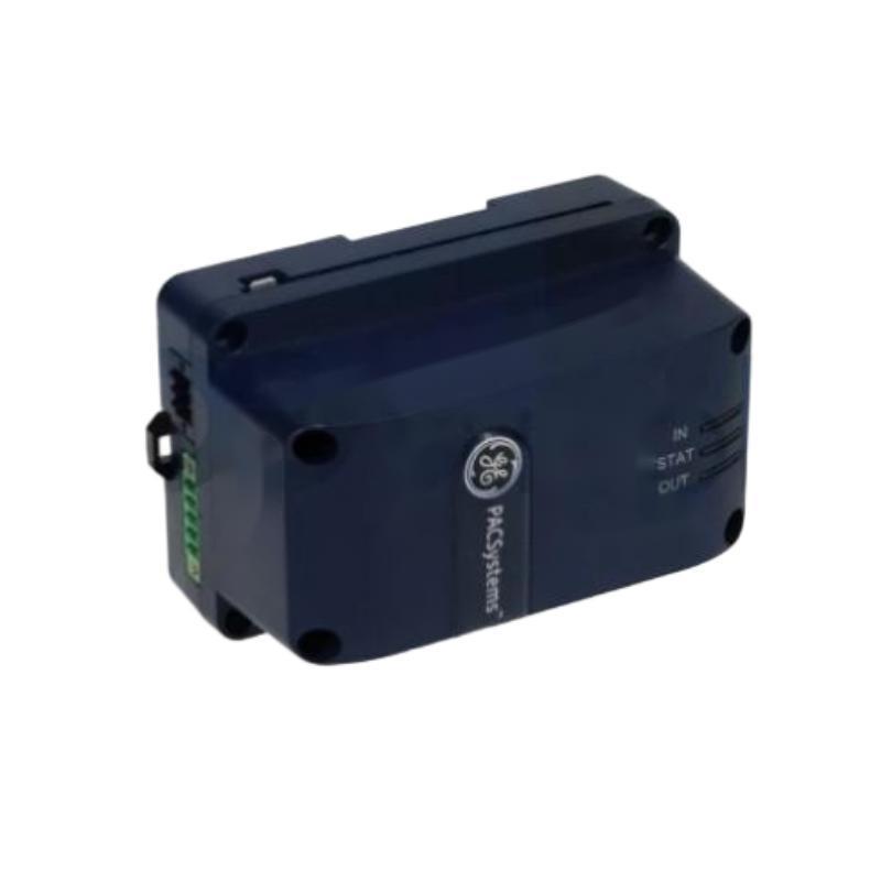
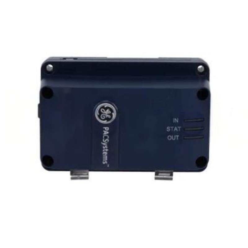
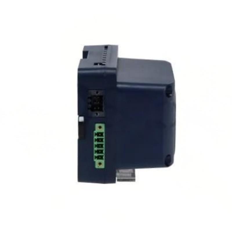
- GE
- IC695ACC402
- RX3I CPU Power Pack
- USA
- 140 x 124 x 25.4 mm
- 0.29 kg
- Xiamen, China
- New & In Stock
- T/T, PayPal, Western Union
- 1 Year
- 1-3 Working Days
- DHL, UPS, TNT, FedEx and EMS.
- 24-Hour Service
- COO
- 7
Our advantage

Global Logistics
We have a 10-year logistics and express cooperation agreement, so our products can be shipped to any place in the world.

Brand new and original
Our products are imported in bulk from the place of origin. Because of the cooperative relationship, our products are all original and 100% new.

24-hour service
We provide 7*24 hours service to our customers. We will be there whenever you need us.

Price advantage
All our products are priced very favorably because we have our own warehouse and supply.
| Company Information | |||
| [email protected] | |||
| Mobile | +8615980777398 | ||
| +8615980777398 | |||
| 15980777398 |
Product Overview
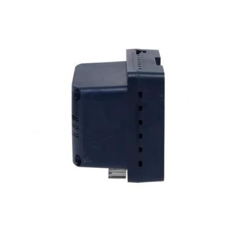
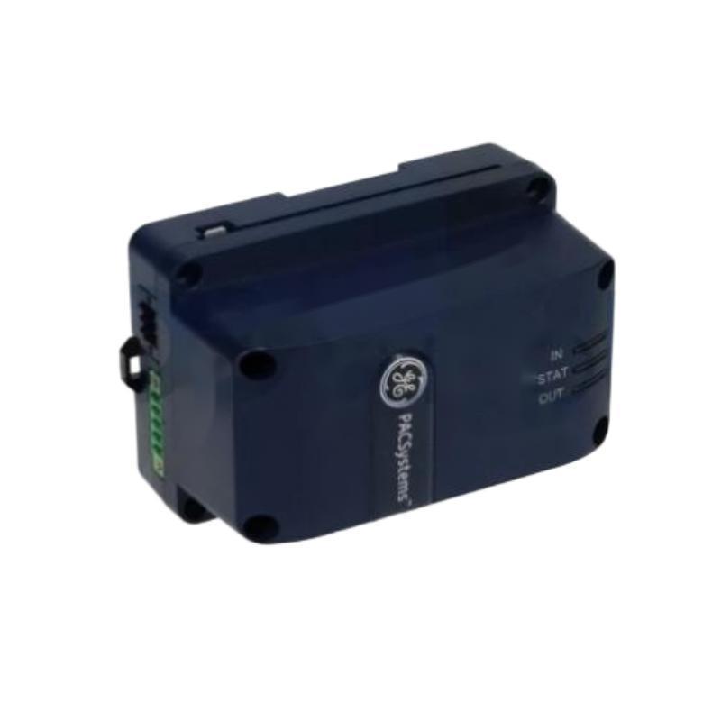
The GE IC695ACC402 RX3i CPU Power Pack is a dedicated power-related component intended for use within compatible GE RX3i industrial automation systems. As part of a PLC control architecture, a CPU power pack provides an important supporting function for the controller and associated control-system hardware.
Reliable power support is essential for PLC operation. Problems involving a power pack, its connections, or the associated power-management circuitry can produce symptoms ranging from startup failures and diagnostic alarms to intermittent controller operation.
The specified dimensions of the GE IC695ACC402 are 140 × 124 × 25.4 mm, with a specified weight of 0.29 kg.
Because the IC695ACC402 is associated with an RX3i CPU system, installation should be performed with attention to controller compatibility, mechanical installation, electrical connections, system shutdown procedures, and post-installation diagnostics.
Product Identification
| Parameter | Specification |
|---|---|
| Manufacturer | GE |
| Series | RX3i |
| Model | IC695ACC402 |
| Product Type | RX3i CPU Power Pack |
| Main Function | CPU Power Support |
| Application | Industrial PLC / Automation |
| Dimensions | 140 × 124 × 25.4 mm |
| Weight | 0.29 kg |
| Installation | Compatible RX3i Control System |
| System Role | CPU Power-Related Component |
| Maintenance Focus | Power Connection and System Diagnostics |
Technical Specifications
| Technical Item | Specification |
|---|---|
| Manufacturer | GE |
| Product Family | RX3i |
| Model | IC695ACC402 |
| Product Category | CPU Power Pack |
| Primary Function | CPU Power Support |
| Dimensions | 140 × 124 × 25.4 mm |
| Weight | 0.29 kg |
| Application | PLC Control System |
| Installation Environment | Industrial Control Cabinet |
| System Integration | RX3i Automation Architecture |
| Maintenance | Power, Connections, and Diagnostics |
| Configuration | Dependent on Compatible RX3i Hardware |
The exact electrical input/output characteristics, connector assignment, power requirements, supported CPU configurations, and operating limits should be confirmed against the applicable system documentation before installation.
What Is the GE IC695ACC402?
The IC695ACC402 is identified as an RX3i CPU Power Pack.
In an industrial PLC system, the CPU is responsible for executing the control program, processing inputs, managing outputs, and coordinating system functions. The associated power architecture must provide the appropriate electrical support for reliable operation.
A simplified system relationship is:
Control Power
↓
CPU Power Pack
↓
RX3i CPU / Controller
↓
I/O and Communication Modules
↓
Field Devices
The exact electrical architecture depends on the RX3i system configuration.
Role in an RX3i Control System
The IC695ACC402 is not a PLC programming CPU itself. Instead, it serves a power-related function within the CPU system.
This distinction is important during troubleshooting.
If a PLC fails to start, technicians should not immediately assume that the CPU program or CPU hardware is defective. The power path should be checked first.
A practical diagnostic structure is:
Power Source → Power Pack → CPU → Backplane/System → I/O
Main Functions
CPU Power Support
The primary role of the power pack is associated with providing or supporting the required power architecture for compatible RX3i CPU equipment.
Stable power is essential for:
- CPU startup
- Controller operation
- System diagnostics
- Communication
- Program execution
- I/O processing
System Startup Support
During PLC startup, the power system must establish appropriate electrical conditions before normal controller operation can begin.
A power-related problem can therefore appear as:
- CPU not starting
- System diagnostic alarms
- Repeated restart
- Unexpected controller shutdown
- Communication loss
- I/O initialization failure
Installation Guide
1. Verify the Model
Before installation, confirm the identification:
GE IC695ACC402
Compare the part number with the equipment documentation.
Do not assume that a similar-looking RX3i component is interchangeable.
2. Inspect the Power Pack
Before installation, inspect the IC695ACC402 for:
- Cracks
- Damaged housing
- Bent or damaged connectors
- Corrosion
- Contamination
- Signs of overheating
- Mechanical deformation
Do not install a visibly damaged component.
3. Confirm Compatibility
Verify:
- RX3i system compatibility
- CPU configuration
- Power architecture
- Connector arrangement
- Mounting requirements
- Electrical requirements
Compatibility should be confirmed from the complete system configuration.
4. Verify Physical Dimensions
The specified dimensions are:
140 × 124 × 25.4 mm
Allow adequate clearance for:
- Installation
- Connector access
- Cable routing
- Ventilation
- Maintenance
Do not install the component in a location where adjacent wiring prevents proper access.
5. Verify Weight
The specified weight is:
0.29 kg
Although the component is relatively lightweight, it should still be securely mounted according to the system’s mechanical requirements.
6. Shut Down the Control System
Before removing or installing the power pack:
- Place the machine in a safe state.
- Stop the PLC-controlled process.
- Shut down the applicable control system.
- Isolate electrical power.
- Apply appropriate lockout/tagout procedures.
- Verify that hazardous voltage has been removed.
- Observe required discharge time for stored electrical energy.
Never remove a power-related component from an energized system unless the applicable system documentation specifically permits that operation.
7. Prepare the Installation Area
Inspect:
- Mounting points
- Connectors
- Adjacent modules
- Wiring
- Cabinet condition
- Cooling and ventilation
Remove dust or contamination using an approved maintenance method.
8. Install the IC695ACC402
Position the power pack correctly and secure it according to the approved mechanical arrangement.
Confirm:
- Correct orientation
- Proper seating
- Secure mounting
- Correct connector engagement
Avoid excessive force during installation.
9. Connect Electrical Interfaces
Reconnect all applicable electrical interfaces according to the system wiring documentation.
Check:
- Connector position
- Cable routing
- Contact condition
- Mechanical engagement
- Strain relief
Do not modify wiring simply to make a connector fit.
10. Inspect Before Energizing
Perform a final inspection.
Confirm:
- No loose tools
- No foreign objects
- Connectors fully engaged
- Wiring correctly routed
- Component securely mounted
- Cabinet ready for controlled startup
Commissioning Procedure
Step 1 – Mechanical Verification
Confirm that the IC695ACC402 is correctly mounted.
Step 2 – Electrical Verification
Check the power connections and associated wiring.
Where applicable, verify the electrical supply according to the approved commissioning procedure.
Step 3 – Power Up
Restore power using the normal RX3i startup procedure.
Observe the system during initialization.
Step 4 – Check CPU Status
Inspect the CPU and system diagnostics.
Look for:
- Normal startup
- Power-related alarms
- CPU faults
- Repeated restart
- Communication initialization problems
Step 5 – Verify I/O Initialization
Confirm that the connected I/O modules initialize normally.
A power problem may prevent downstream modules from starting correctly.
Step 6 – Verify Communications
Where applicable, confirm communication with:
- Programming workstation
- Remote I/O
- Network modules
- HMI
- Supervisory systems
Step 7 – Functional Test
Run the machine or process through a controlled test.
Verify:
- CPU operation
- I/O response
- Communication
- Interlocks
- Alarms
- Normal control sequence
Troubleshooting Guide
Fault 1 – RX3i CPU Does Not Start
Possible Causes
- Power supply problem
- Power pack connection problem
- Loose connector
- Incorrect installation
- Damaged power pack
- CPU hardware fault
- System configuration issue
Diagnostic Sequence
Check:
Incoming Power → Power System → IC695ACC402 → CPU → System Backplane
Do not immediately replace the CPU.
Fault 2 – CPU Repeatedly Restarts
Repeated restarts may indicate:
- Unstable power
- Poor electrical connection
- Power pack problem
- Overload
- Thermal issue
- CPU fault
Monitor the system during startup and review available diagnostics.
Fault 3 – Power-Related Diagnostic Alarm
Possible causes include:
- Incorrect power conditions
- Loose connection
- Power pack failure
- Associated power-system fault
- Overload
Verify the complete power path.
Fault 4 – CPU Loses Power Intermittently
Intermittent power loss can result from:
- Loose connectors
- Damaged cables
- Mechanical vibration
- Poor contact
- Power-source instability
- Internal power-pack fault
Inspect physical connections first.
Fault 5 – I/O Modules Fail to Initialize
If the CPU starts but multiple I/O modules fail to initialize, investigate:
- System power
- Backplane connections
- CPU status
- Power architecture
- Module seating
- System configuration
A common power problem can affect several modules simultaneously.
Fault 6 – Communication Is Lost
If communication is lost after a power-related event, check:
- CPU status
- Power system
- Network module status
- Network cabling
- Controller diagnostics
A power interruption may cause communication modules to restart.
Fault 7 – Power Pack Becomes Hot
Abnormal heating may indicate:
- Overload
- Electrical fault
- Poor ventilation
- Excessive ambient temperature
- Internal component failure
Do not continue operation without determining the cause of abnormal heating.
Fault 8 – System Shuts Down During Operation
Possible causes include:
- Power interruption
- Power instability
- Loose connection
- Thermal protection
- Power pack failure
- External power supply problem
Determine whether the shutdown originates upstream or within the RX3i system.
Fault 9 – Fault Appears After Maintenance
If the system worked correctly before maintenance, check for:
- Incorrect connector
- Incomplete connector engagement
- Loose wiring
- Improper module installation
- Disturbed adjacent components
Maintenance-related installation errors should be ruled out before replacing hardware.
Fault 10 – System Works Temporarily Then Stops
This type of fault may indicate:
- Thermal problems
- Power instability
- Intermittent connection
- Overload
- Component degradation
Monitor the system over time rather than performing only a brief startup test.
Troubleshooting Flowchart
A practical diagnostic sequence is:
Incoming Control Power
↓
System Power Supply
↓
IC695ACC402
↓
RX3i CPU
↓
Backplane / System Modules
↓
I/O and Communication
↓
Field Equipment
This sequence helps technicians isolate whether a fault originates from the power source, power pack, controller, or downstream equipment.
Preventive Maintenance
Visual Inspection
Inspect periodically for:
- Housing damage
- Connector damage
- Discoloration
- Dust accumulation
- Corrosion
- Signs of overheating
Connector Inspection
Check for:
- Loose connections
- Contamination
- Damaged contacts
- Mechanical wear
- Cable strain
Avoid unnecessary connector cycling.
Cabinet Environment
Maintain suitable:
- Temperature
- Humidity
- Ventilation
- Cleanliness
Excessive heat can shorten the life of electronic power components.
Power Quality
Where required by the system maintenance program, monitor the incoming power system for:
- Voltage instability
- Interruptions
- Electrical noise
- Overvoltage
- Undervoltage
Power-quality problems upstream can appear to be power-pack faults.
Maintenance Documentation
Maintain records of:
- Installation date
- Replacement date
- System location
- Diagnostic alarms
- Maintenance actions
- Power-related failures
Good records can help identify recurring system problems.
Preventive Maintenance Table
| Maintenance Area | Recommended Action |
|---|---|
| Housing | Inspect for damage |
| Connectors | Check condition and engagement |
| Wiring | Inspect for mechanical stress |
| Cabinet | Keep clean and ventilated |
| Temperature | Monitor for overheating |
| Power | Check system supply condition |
| Diagnostics | Review CPU/system alarms |
| Mounting | Verify mechanical stability |
| Maintenance Records | Document abnormalities |
| System Test | Verify normal startup and operation |
Industrial Applications
Manufacturing Automation
RX3i-based control systems can be used in automated manufacturing environments where stable PLC operation is essential for machine sequencing and production control.
Machine Control
Industrial machinery often depends on continuous CPU operation for:
- Motion coordination
- Sensor processing
- Interlocks
- Actuator control
- Alarm management
Power-related reliability is therefore critical.
Production Lines
Production lines may contain multiple PLC-controlled stations.
A power-pack problem can potentially affect controller availability and interrupt production.
Process Equipment
Industrial process equipment can require continuous controller operation for:
- Pump control
- Valve control
- Interlocks
- Monitoring
- Alarm processing
Reliable power support contributes to stable control operation.
Material Handling
Automated conveyors, sorting systems, and handling equipment may use PLC control architectures with multiple I/O and communication modules.
Stable CPU power is important for coordinated operation.
Infrastructure Automation
Industrial infrastructure systems may use PLC-based control for equipment monitoring and sequencing.
Power-related diagnostics should therefore be included in preventive maintenance programs.
Replacement Procedure
1. Identify the Existing Component
Confirm that the installed component is:
GE IC695ACC402
Record its location and associated system configuration.
2. Back Up the PLC Program
Before performing significant controller maintenance, maintain a current backup of:
- PLC program
- Hardware configuration
- System parameters
- Relevant application settings
3. Review the System Shutdown Procedure
Determine the correct shutdown sequence for the RX3i system.
Avoid abrupt power removal when it could create unsafe machine conditions.
4. Isolate Power
Disconnect the applicable electrical supply and verify safe conditions.
5. Disconnect the Existing Power Pack
Release the component according to the approved mechanical and electrical procedure.
Avoid pulling directly on cables.
6. Inspect the System
Before installing the replacement, inspect:
- Connectors
- Mounting points
- Adjacent modules
- Wiring
- Cabinet condition
7. Install the Replacement IC695ACC402
Install the replacement power pack in the correct position.
Confirm proper mechanical seating.
8. Reconnect Interfaces
Reconnect all applicable connections.
Verify connector engagement and cable routing.
9. Restore Power
Restore the system power according to the approved startup procedure.
10. Verify Operation
Check:
- CPU startup
- System diagnostics
- I/O initialization
- Communications
- Machine sequence
- Alarm status
Replacement Considerations
| Parameter | Specification / Check |
|---|---|
| Manufacturer | GE |
| Series | RX3i |
| Model | IC695ACC402 |
| Product Type | RX3i CPU Power Pack |
| Dimensions | 140 × 124 × 25.4 mm |
| Weight | 0.29 kg |
| CPU Compatibility | Confirm |
| Electrical Characteristics | Confirm |
| Connector Configuration | Confirm |
| Mounting Arrangement | Confirm |
| System Configuration | Confirm |
| Environmental Requirements | Confirm |
A replacement should be selected based on complete system compatibility. Matching dimensions alone does not guarantee that a power component is electrically suitable.
Key Advantages
- Designed for compatible GE RX3i control systems
- Dedicated CPU-related power support
- Compact form factor
- Lightweight design
- Supports stable controller operation
- Integrates into industrial PLC architectures
- Useful for structured power-system maintenance
- Specified dimensions of 140 × 124 × 25.4 mm
- Specified weight of 0.29 kg
Technical FAQs
What is the GE IC695ACC402?
The GE IC695ACC402 is an RX3i CPU Power Pack designed for use within compatible GE RX3i industrial automation systems.
What are the dimensions of the IC695ACC402?
The specified dimensions are 140 × 124 × 25.4 mm.
What is the weight of the IC695ACC402?
The specified weight is 0.29 kg.
Is the IC695ACC402 a PLC CPU?
No. It is identified as a CPU power pack and should not be confused with the RX3i CPU itself.
Why is the power pack important?
Reliable electrical power is fundamental to CPU operation. Power-related faults can prevent startup, cause restarts, interrupt communications, or affect downstream I/O operation.
What should I check if the RX3i CPU does not start?
Start with the incoming power and follow the path through the system power supply, IC695ACC402, CPU, and system connections.
Can a loose connector cause CPU problems?
Yes. A poor connection can cause intermittent power loss, startup failures, diagnostic alarms, or unexpected controller resets.
Why might the CPU repeatedly restart?
Possible causes include unstable power, poor connections, overload, thermal conditions, or hardware faults.
What should be checked before replacing the IC695ACC402?
Verify incoming power, associated power components, connectors, wiring, CPU status, system configuration, and diagnostic information.
Can a power problem affect multiple I/O modules?
Yes. A common power-system problem can prevent several downstream modules from operating correctly.
Why is cabinet temperature important?
Excessive temperature can increase electrical component stress and may contribute to intermittent or premature hardware failures.
Should the PLC program be backed up before replacement?
Maintaining a current backup of the PLC program and hardware configuration is strongly recommended before controller-system maintenance.
Conclusion
The GE IC695ACC402 RX3i CPU Power Pack is a dedicated power-related component used within compatible GE RX3i industrial automation architectures. With specified dimensions of 140 × 124 × 25.4 mm and a specified weight of 0.29 kg, it provides a compact component for CPU-related power support.
Reliable power is one of the foundations of PLC system stability. A problem with the power pack, its connectors, the upstream power source, or associated power architecture can produce symptoms that appear to be CPU, communication, or I/O failures. For this reason, troubleshooting should begin with the power path before replacing expensive control hardware.
Proper installation requires model verification, compatibility checking, safe system shutdown, careful connector handling, secure mounting, and controlled commissioning. Preventive maintenance should include visual inspection, connector checks, cabinet-environment monitoring, power-quality evaluation where appropriate, and review of system diagnostics.
When replacing an IC695ACC402, technicians should also maintain current PLC program and configuration backups and verify CPU, I/O, communications, and machine operation after installation. A systematic approach to power-related maintenance can reduce unnecessary hardware replacement and help maintain reliable operation of GE RX3i automation systems.