

ProductPRODUCT
Featured products



Contact Us
- GE
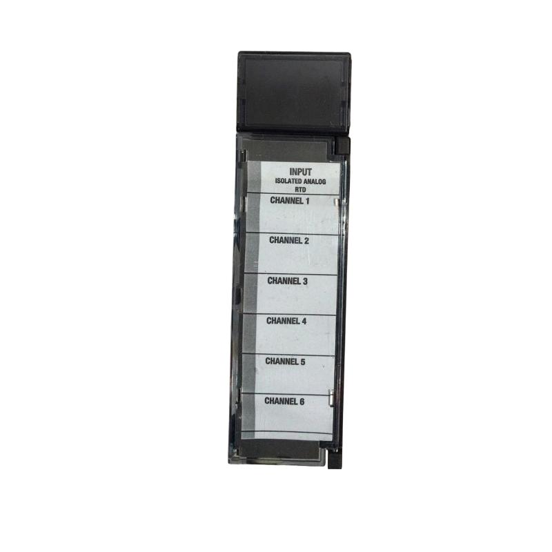
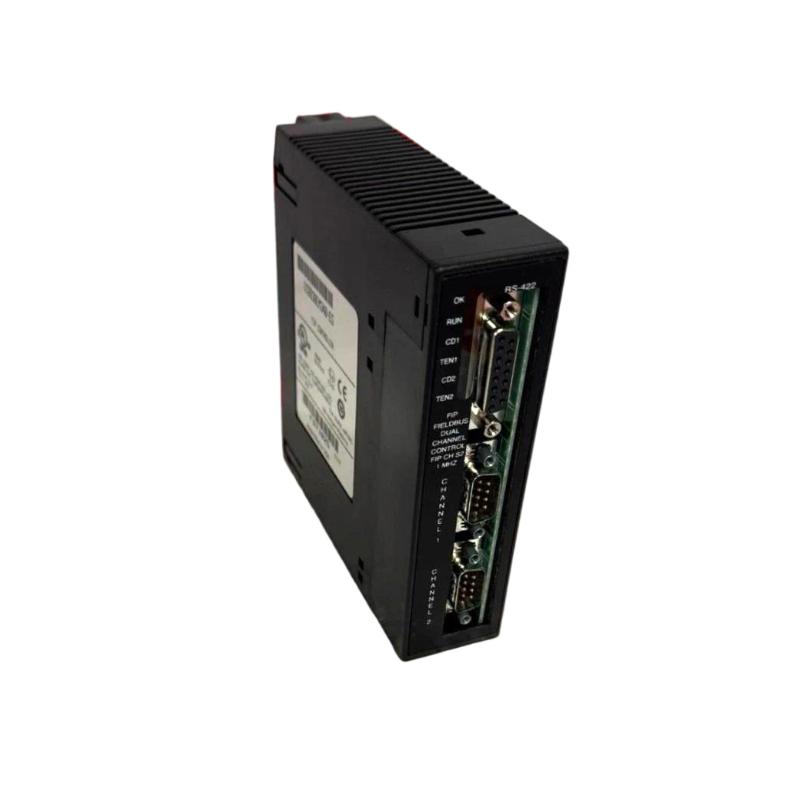
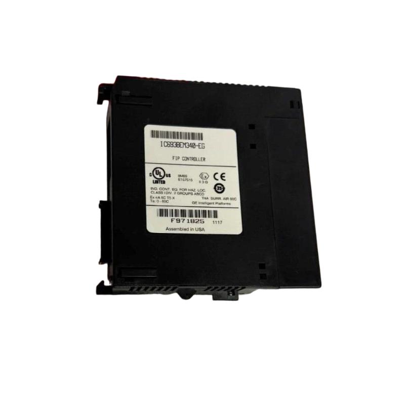
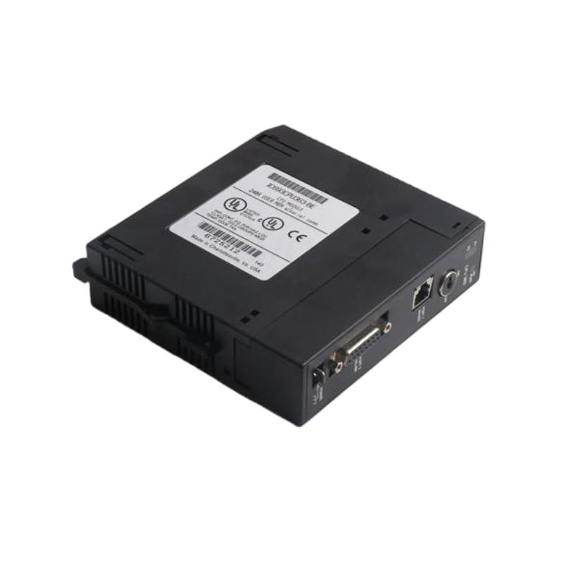
- GE IC694BEM340
- Bus Controller
- USA
- 145 x 34 x 140 mm
- 0.37 kg
- Xiamen, China
- New & In Stock
- T/T, PayPal, Western Union
- 1 Year
- 1-3 Working Days
- DHL, UPS, TNT, FedEx and EMS.
- 24-Hour Service
- COO
- 51
Our advantage

Global Logistics
We have a 10-year logistics and express cooperation agreement, so our products can be shipped to any place in the world.

Brand new and original
Our products are imported in bulk from the place of origin. Because of the cooperative relationship, our products are all original and 100% new.

24-hour service
We provide 7*24 hours service to our customers. We will be there whenever you need us.

Price advantage
All our products are priced very favorably because we have our own warehouse and supply.
| Company Information | |||
| [email protected] | |||
| Mobile | +8615980777398 | ||
| +8615980777398 | |||
| 15980777398 |
Product Overview
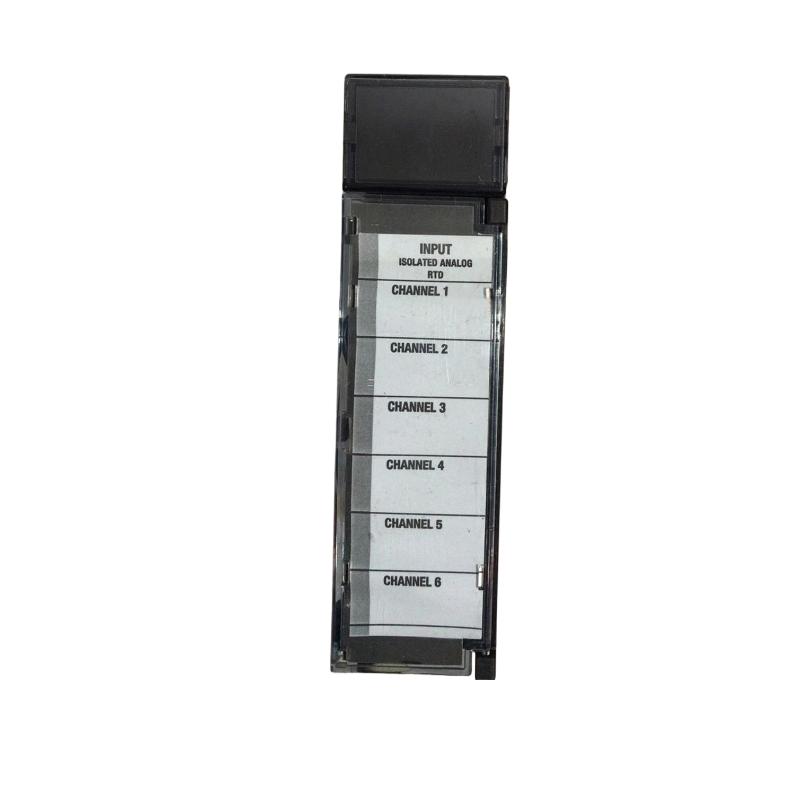
The GE IC694BEM340 Bus Controller is an industrial automation communication component designed to provide a controlled interface between a PLC system and an associated field or remote bus architecture.
In a distributed automation system, the controller does not always communicate directly with every field device through the main CPU. Instead, a bus controller can manage communication between the PLC backplane and devices connected to a remote or specialized network. This approach allows control architectures to distribute I/O and other devices across a machine or plant while maintaining centralized PLC control.
The specified dimensions of the GE IC694BEM340 are 145 × 34 × 140 mm, with a specified weight of 0.37 kg.
The IC694BEM340 should therefore be viewed as a communication-oriented component within the overall control architecture rather than as a conventional discrete input or output module.
Product Identification
| Parameter | Specification |
|---|---|
| Manufacturer | GE |
| Series | IC694 |
| Model | IC694BEM340 |
| Product Type | Bus Controller |
| Main Function | Industrial Bus Communication |
| Application | PLC / Distributed Automation |
| Dimensions | 145 × 34 × 140 mm |
| Weight | 0.37 kg |
| Installation | PLC Rack / Control Cabinet |
| Communication Role | Bus Interface and Control |
| Typical Application | Distributed I/O and Networked Control |
| Maintenance | Communication and Wiring Inspection |
Technical Specifications
| Technical Item | Specification |
|---|---|
| Manufacturer | GE |
| Model | IC694BEM340 |
| Product Category | Bus Controller |
| Main Function | Bus Communication Management |
| Dimensions | 145 × 34 × 140 mm |
| Weight | 0.37 kg |
| Installation Environment | Industrial Control Cabinet |
| System Role | Network / Bus Interface |
| Application | Distributed Automation |
| Communication | Bus-Based Industrial Communication |
| Maintenance | Diagnostic and Network Inspection |
The exact bus protocol, supported devices, communication parameters, node configuration, cable requirements, termination requirements, and maximum network architecture should be confirmed against the applicable system documentation before installation.
Role of the IC694BEM340 in a PLC System
A typical distributed architecture can be represented as:
PLC CPU
↓
IC694BEM340 Bus Controller
↓
Industrial Bus
↓
Remote / Distributed Devices
↓
Sensors and Actuators
The bus controller acts as the communication bridge between the PLC system and the connected bus devices.
This architecture can provide advantages such as:
- Distributed I/O
- Reduced point-to-point wiring
- Flexible machine architecture
- Remote device integration
- Centralized control
- Easier system expansion
Why Bus Controllers Are Used
Traditional PLC installations can require large quantities of field wiring.
For example:
Sensor 1 → PLC
Sensor 2 → PLC
Sensor 3 → PLC
Actuator 1 → PLC
Actuator 2 → PLC
As system size increases, wiring can become complicated.
A distributed architecture can instead use:
PLC
↓
Bus Controller
↓
Remote I/O
↓
Field Devices
This can reduce the amount of long-distance point-to-point wiring and provide a more structured control architecture.
Installation Guide
1. Verify the Module
Confirm the module identification:
GE IC694BEM340
Inspect the unit for:
- Cracks
- Damaged housing
- Bent connectors
- Corrosion
- Contamination
- Damaged terminals
- Signs of impact
Do not install a damaged module.
2. Verify System Compatibility
Before installation, confirm:
- PLC platform
- Rack compatibility
- Controller compatibility
- Bus architecture
- Supported remote devices
- Network configuration
- Power requirements
A bus controller must be compatible with the complete communication architecture.
3. Check Module Dimensions
The specified dimensions are:
145 × 34 × 140 mm
Allow adequate cabinet space for:
- Module insertion
- Cable connection
- Connector access
- Ventilation
- Maintenance
- Cable routing
Avoid placing high-heat equipment directly against the module.
4. Consider Module Weight
The specified weight is:
0.37 kg
The rack should provide adequate mechanical support.
Communication cables should also be routed so that they do not exert excessive mechanical force on the module connector.
5. Power Isolation
Before installation or removal:
- Place the machine in a safe state.
- Shut down the appropriate equipment.
- Isolate power as required.
- Apply lockout/tagout procedures.
- Verify the absence of hazardous energy.
- Follow plant safety procedures.
6. Install the Module
Align the IC694BEM340 with the intended rack position.
Insert the module carefully and ensure that it is fully seated.
Avoid:
- Forcing the module
- Misalignment
- Twisting
- Excessive pressure
- Impact
7. Secure the Module
After insertion, verify:
- Proper seating
- Mechanical retention
- Connector engagement
- Alignment
- Clearance from adjacent modules
A poor mechanical connection can lead to intermittent communication problems.
Bus Network Installation
Cable Selection
Use the appropriate communication cable for the specific bus architecture.
Cable characteristics can affect:
- Signal quality
- Communication distance
- Noise immunity
- Network reliability
- Maximum communication speed
Do not substitute an arbitrary cable simply because it physically fits the connector.
Network Routing
Where practical, route communication cables away from major electrical noise sources such as:
- Motor power cables
- Variable-frequency drive output cables
- Welding equipment
- Large contactors
- High-current conductors
This helps reduce electromagnetic interference.
Shielding
If the communication architecture requires shielded cable, follow the applicable grounding arrangement.
Incorrect shield connections can sometimes introduce ground-loop problems, so the shield should be connected according to the system’s electrical design.
Network Topology
The supported topology depends on the specific bus architecture.
Before commissioning, verify:
- Node arrangement
- Device order
- Cable routing
- Termination
- Network length
- Addressing
Incorrect topology or termination can result in unstable communication.
Node Addressing
If the bus architecture requires device addresses, every participating device must have a unique and valid address.
Duplicate addressing can cause:
- Communication conflicts
- Missing devices
- Intermittent data
- Network startup failure
Record network addresses during installation.
Commissioning Procedure
Step 1 – Hardware Inspection
Verify:
- IC694BEM340 installed correctly
- Rack connection secure
- Network cable connected
- Remote devices powered
- Termination installed where required
Step 2 – Check Network Configuration
Confirm:
- Bus type
- Device addresses
- Communication settings
- Node configuration
- I/O mapping
- Controller configuration
Step 3 – Power Up
Apply system power according to the commissioning procedure.
Observe:
- Module status
- Controller status
- Network indicators
- Remote device status
- Diagnostic information
Step 4 – Confirm Network Initialization
Verify that the bus controller recognizes the expected network devices.
Check for:
- Missing nodes
- Communication errors
- Configuration mismatches
- Bus faults
Step 5 – Verify Data Exchange
Test representative inputs and outputs.
For example:
Remote Sensor
↓
Bus Network
↓
IC694BEM340
↓
PLC
Verify that the PLC receives the correct status.
Then test an output:
PLC Command
↓
IC694BEM340
↓
Bus
↓
Remote Output
↓
Actuator
Confirm that the field device responds correctly.
Step 6 – Test Under Normal Conditions
Operate the machine at normal conditions.
Monitor:
- Communication stability
- Diagnostic status
- Remote I/O response
- Network errors
- Data consistency
Allow sufficient operating time to identify intermittent communication problems.
Troubleshooting Guide
Fault 1 – Bus Controller Does Not Start
Possible Causes
- Module not seated correctly
- Rack power problem
- Configuration issue
- Controller compatibility problem
- Hardware fault
Diagnostic Procedure
Check:
- Rack power.
- Module seating.
- Controller configuration.
- Diagnostic indicators.
- Network connection.
Fault 2 – Remote Devices Are Not Detected
Possible Causes
- Network cable disconnected
- Incorrect addressing
- Missing termination
- Configuration mismatch
- Remote device power loss
- Bus wiring problem
Corrective Action
Check the network progressively:
Controller → Cable → Network → Remote Device
Fault 3 – Intermittent Communication
Possible Causes
- Loose connector
- Damaged communication cable
- Electromagnetic interference
- Incorrect termination
- Poor grounding
- Network topology problem
- Temperature or vibration
Intermittent communication faults are often caused by physical network problems rather than the controller itself.
Fault 4 – Entire Bus Goes Offline
Possible Causes
- Bus controller failure
- Network power loss
- Broken trunk cable
- Incorrect termination
- Major wiring fault
- Configuration error
Check common network components first.
Fault 5 – Only One Remote Device Is Missing
If most devices communicate normally while one node is missing, investigate the individual node.
Possible causes include:
- Local power loss
- Incorrect address
- Damaged cable
- Connector problem
- Device configuration issue
- Failed remote module
Fault 6 – Multiple Remote Devices Disappear
Possible Causes
- Common network cable problem
- Network power failure
- Bus controller problem
- Incorrect topology
- Termination issue
Check the shared portion of the network before replacing individual devices.
Fault 7 – Communication Errors Increase During Motor Operation
Possible Causes
- Electromagnetic interference
- Poor cable routing
- Inadequate shielding
- Grounding problem
- Damaged communication cable
Compare communication behavior with motors or drives stopped and operating.
If errors correlate with motor operation, investigate EMC conditions.
Fault 8 – Data Values Are Incorrect
Communication may appear active while data mapping is incorrect.
Possible causes:
- Incorrect I/O mapping
- Configuration mismatch
- Wrong device address
- Incorrect data interpretation
- PLC program problem
Verify both network configuration and PLC logic.
Fault 9 – Remote Output Does Not Respond
Possible Causes
- PLC command not generated
- Communication problem
- Incorrect output mapping
- Remote output fault
- Field power problem
- Actuator failure
Trace the command from:
PLC Logic → Bus Controller → Network → Remote Output → Actuator
Fault 10 – Communication Fails After Maintenance
If communication worked before maintenance but fails afterward, inspect:
- Module seating
- Cable connectors
- Network wiring
- Termination
- Power connections
- Configuration changes
Maintenance-related communication failures are frequently caused by disturbed connections.
Fault Diagnosis Flow
Use a structured sequence:
PLC CPU
↓
IC694BEM340
↓
Bus Cable
↓
Network Infrastructure
↓
Remote Device
↓
Field Wiring
↓
Sensor / Actuator
This helps isolate communication faults efficiently.
Preventive Maintenance
Module Inspection
Inspect the IC694BEM340 for:
- Physical damage
- Contamination
- Corrosion
- Loose mounting
- Connector damage
- Abnormal indicators
Cable Inspection
Check communication cables for:
- Cuts
- Abrasion
- Crushing
- Excessive bending
- Loose connectors
- Damaged shielding
Connector Inspection
Inspect connectors for:
- Loose engagement
- Corrosion
- Contamination
- Damaged contacts
- Mechanical damage
A poor connector can create intermittent network failures.
Network Configuration Backup
Maintain an up-to-date record of:
- Controller configuration
- Device addresses
- Network topology
- I/O mapping
- Termination locations
- Communication settings
This information can greatly accelerate troubleshooting and replacement.
Preventive Maintenance Table
| Maintenance Area | Recommended Action |
|---|---|
| Module | Inspect housing and indicators |
| Rack | Verify module seating |
| Connectors | Check secure engagement |
| Network Cable | Inspect physical condition |
| Shielding | Verify according to system design |
| Termination | Confirm correct installation |
| Device Addresses | Check configuration |
| Network Topology | Verify against drawings |
| Diagnostics | Review communication errors |
| Cabinet | Maintain clean and dry conditions |
| Documentation | Keep network records current |
Industrial Applications
Distributed I/O
A bus controller can support architectures where I/O devices are physically distributed across a machine.
This can reduce the quantity of long field wires returning to the central control cabinet.
Machine Automation
Distributed control can be useful on large machines containing multiple sections.
For example:
Central PLC
↓
Bus Controller
↓
Machine Section A
Machine Section B
Machine Section C
This architecture can simplify physical system organization.
Material Handling
Conveyor systems often contain sensors and actuators distributed over substantial physical distances.
A network-based architecture can provide a structured method for collecting and distributing control signals.
Packaging Systems
Packaging equipment may have multiple machine stations containing:
- Sensors
- Valves
- Motors
- Actuators
- Position devices
Distributed communication can simplify the connection of these devices to the main controller.
Process Automation
Distributed device architectures can also be useful where field devices are physically separated from the primary control cabinet.
System Integration
A typical control architecture can be represented as:
Engineering / HMI
↓
PLC CPU
↓
IC694BEM340
↓
Industrial Bus
↓
Remote I/O
↓
Field Devices
The controller serves as a critical communication point within this architecture.
Bus Controller vs. Standard I/O Module
| Characteristic | Bus Controller | Standard I/O Module |
|---|---|---|
| Primary Function | Network Communication | Signal Interface |
| Connects to Field Network | Yes, where supported | Usually No |
| Handles Remote Devices | Yes | Typically Local |
| Digital Inputs | Not its primary role | Common |
| Digital Outputs | Not its primary role | Common |
| Network Configuration | Important | Usually Limited |
| Main Troubleshooting Focus | Network | Signal / Wiring |
The bus controller should therefore be diagnosed differently from conventional input and output modules.
Replacement Procedure
When replacing the IC694BEM340:
1. Record Configuration
Before removal, record:
- Module position
- Network configuration
- Device addresses
- Communication settings
- I/O mapping
- Network topology
2. Isolate Power
Follow the appropriate shutdown and lockout/tagout procedure.
3. Remove Network Connections
Disconnect the communication cable carefully.
Protect connectors from contamination and mechanical damage.
4. Remove the Module
Release the applicable retaining mechanism and remove the module carefully.
5. Install Replacement
Install the replacement IC694BEM340 in the correct rack position.
Ensure proper seating.
6. Reconnect the Network
Reconnect the communication cable.
Verify:
- Correct connector
- Secure engagement
- Proper cable routing
- Correct termination
7. Restore Configuration
Apply the appropriate configuration and verify network parameters.
8. Test Communication
Confirm:
- Controller startup
- Network initialization
- Remote-device detection
- I/O data exchange
- Machine operation
Replacement Considerations
| Parameter | Specification / Check |
|---|---|
| Manufacturer | GE |
| Model | IC694BEM340 |
| Product Type | Bus Controller |
| Dimensions | 145 × 34 × 140 mm |
| Weight | 0.37 kg |
| Rack Compatibility | Confirm |
| Bus Compatibility | Confirm |
| Network Configuration | Confirm |
| Device Addresses | Confirm |
| Connector Type | Confirm |
| Cable Requirements | Confirm |
| Termination Requirements | Confirm |
Physical dimensions alone should not be used to determine whether a replacement module is suitable.
Key Advantages
- Provides a communication interface for compatible industrial bus architectures
- Supports distributed automation concepts
- Helps connect PLC control with remote devices
- Can reduce long point-to-point field wiring
- Supports structured machine networking
- Useful for distributed I/O applications
- Suitable for industrial control cabinets
- Compact module design
- Dimensions: 145 × 34 × 140 mm
- Weight: 0.37 kg
- Supports centralized PLC control with distributed field devices
Technical FAQs
What is the GE IC694BEM340?
The GE IC694BEM340 is identified as a bus controller used as a communication interface within compatible industrial automation architectures.
What are the dimensions of the IC694BEM340?
The specified dimensions are 145 × 34 × 140 mm.
What is the weight of the IC694BEM340?
The specified weight is 0.37 kg.
What is the purpose of a bus controller?
A bus controller manages communication between the PLC system and devices connected through a compatible industrial bus architecture.
Can the IC694BEM340 replace a standard digital input module?
No. A bus controller and digital input module perform different functions. The bus controller primarily manages communication, while a digital input module processes field input signals.
Why are remote I/O systems useful?
They can distribute I/O closer to field devices, potentially reducing long point-to-point wiring and simplifying large machine architectures.
Why might remote devices disappear from the network?
Possible causes include cable faults, power loss, incorrect addressing, termination problems, configuration errors, or a communication-controller problem.
Why does communication become unstable when motors start?
Motor drives and high-current equipment can create electromagnetic interference. Cable routing, shielding, grounding, and network installation should be investigated.
What should be checked if only one remote device is missing?
Check that device’s power, address, cable, connector, configuration, and local hardware.
Why is network termination important?
Improper termination can cause signal reflections and communication instability in bus architectures where termination is required.
What should be recorded before replacing the controller?
Record the module position, network topology, device addresses, configuration parameters, I/O mapping, cable arrangement, and applicable termination locations.
Can a bus controller fault cause multiple I/O devices to stop communicating?
Yes. Because the bus controller can serve as a common communication interface, a controller or shared-network fault can affect multiple remote devices simultaneously.
Conclusion
The GE IC694BEM340 Bus Controller provides an important communication function within compatible industrial automation systems. With specified dimensions of 145 × 34 × 140 mm and a weight of 0.37 kg, it can be integrated into PLC rack architectures where distributed or networked devices are required.
Its primary role is to provide a structured communication path between the PLC control system and compatible bus-connected devices. This makes it particularly useful in distributed I/O, machine automation, material handling, packaging, and other industrial applications where field devices may be physically separated from the central controller.
Successful installation depends on correct rack compatibility, network configuration, cable selection, topology, addressing, shielding, grounding, and termination. During commissioning, technicians should verify both network initialization and actual I/O data exchange rather than relying only on module status indicators.
When troubleshooting, follow the communication path from the PLC CPU → IC694BEM340 → bus network → remote device → field equipment. This systematic approach makes it easier to distinguish controller faults from cable, configuration, network, remote I/O, and field-device problems, helping reduce unnecessary replacement and unplanned downtime.