

ProductPRODUCT
Featured products
Contact Us
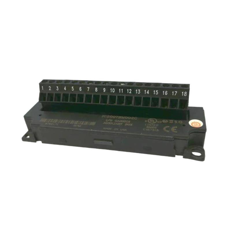
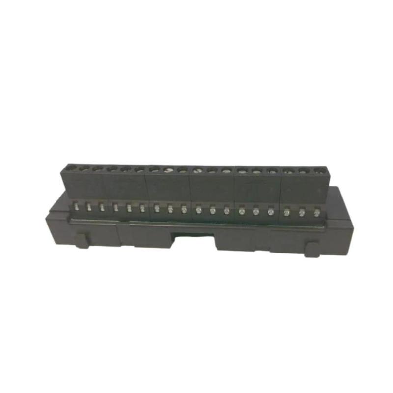
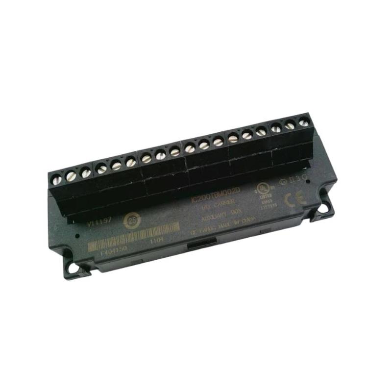
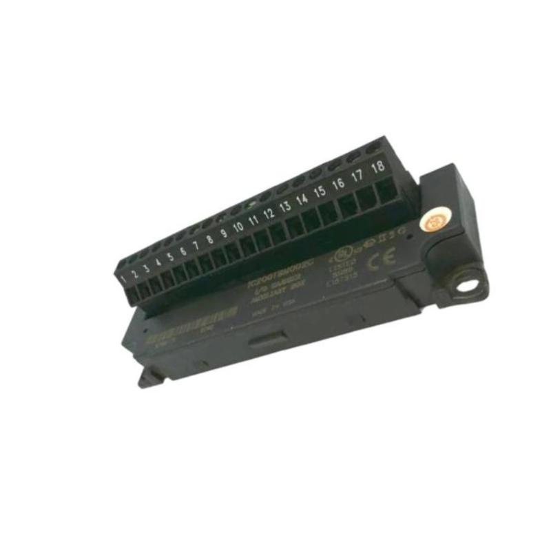
- GE
- IC200TBM002
- VersaMax I/O Auxiliary Box Junction Board
- USA
- 55 x 33 x 20 mm
- 0.068 kg
- Xiamen, China
- New & In Stock
- T/T, PayPal, Western Union
- 1 Year
- 1-3 Working Days
- DHL, UPS, TNT, FedEx and EMS.
- 24-Hour Service
- COO
- 9
Our advantage

Global Logistics
We have a 10-year logistics and express cooperation agreement, so our products can be shipped to any place in the world.

Brand new and original
Our products are imported in bulk from the place of origin. Because of the cooperative relationship, our products are all original and 100% new.

24-hour service
We provide 7*24 hours service to our customers. We will be there whenever you need us.

Price advantage
All our products are priced very favorably because we have our own warehouse and supply.
| Company Information | |||
| [email protected] | |||
| Mobile | +8615980777398 | ||
| +8615980777398 | |||
| 15980777398 |
Product Overview
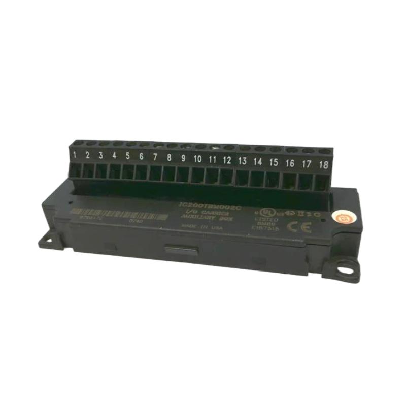
The GE IC200TBM002 VersaMax I/O Auxiliary Box Junction Board is a compact interface component designed for GE VersaMax industrial automation systems. It provides an auxiliary connection point for I/O-related wiring and helps organize electrical connections within a VersaMax control installation.
In a modular PLC system, terminal and junction components are important because they provide a practical interface between field wiring and the automation hardware. A properly installed auxiliary junction board can simplify cabinet wiring, improve connection organization, and make maintenance and troubleshooting more efficient.
The IC200TBM002 is particularly useful where multiple field signals must be routed cleanly between field devices and VersaMax I/O hardware. Its compact dimensions allow it to be incorporated into control cabinets with limited installation space.
The supplied product information is:
- Manufacturer: GE
- Product Family: VersaMax
- Model: IC200TBM002
- Product Type: VersaMax I/O Auxiliary Box Junction Board
- Dimensions: 55 × 33 × 20 mm
- Weight: 0.068 kg
- Application: Industrial Automation
- Primary Function: I/O Auxiliary Wiring and Junction Interface
The exact terminal assignment, electrical ratings, and compatible I/O configuration should always be verified against the system’s approved electrical drawings before wiring.
Technical Specifications
| Parameter | Specification |
|---|---|
| Manufacturer | GE |
| Product Family | VersaMax |
| Model | IC200TBM002 |
| Product Type | VersaMax I/O Auxiliary Box Junction Board |
| Primary Function | I/O Wiring Interface |
| Application | Industrial Automation |
| System Platform | VersaMax |
| Dimensions | 55 × 33 × 20 mm |
| Weight | 0.068 kg |
| Installation | Industrial Control Cabinet |
| Interface Type | Auxiliary I/O Connection |
| Typical Use | Field Wiring and I/O Signal Distribution |
Function and Working Principle
The IC200TBM002 functions as an auxiliary junction and wiring interface within a VersaMax I/O installation.
A typical signal path can be represented as:
Field Sensor / Actuator
↓
Field Wiring
↓
IC200TBM002 Auxiliary Junction Board
↓
VersaMax I/O Interface
↓
PLC Backplane
↓
CPU
The board does not replace the PLC CPU or I/O processing electronics. Instead, it provides an organized connection point for I/O-related wiring.
Its practical functions can include:
- Organizing field wiring
- Providing an auxiliary connection interface
- Simplifying cabinet wiring
- Improving accessibility for maintenance
- Supporting orderly I/O signal routing
- Reducing wiring congestion
- Making fault isolation easier
Because signal quality depends heavily on connection integrity, correct installation of the junction board is important for reliable PLC operation.
Role in Industrial Control Systems
In a VersaMax control cabinet, the IC200TBM002 can act as an intermediate wiring interface between field devices and I/O hardware.
Its role is particularly valuable when:
- Multiple field signals are present
- Cabinet wiring must remain organized
- Maintenance access is important
- Field cables need structured termination
- I/O connections require clear identification
A well-organized junction interface can reduce troubleshooting time because technicians can trace individual signals more easily.
Typical Industrial Applications
Manufacturing Automation
The IC200TBM002 can be incorporated into control panels for:
- Assembly machines
- Production lines
- Material handling equipment
- Conveyor systems
- Automated inspection equipment
- Machine control systems
Packaging Machinery
Packaging systems often contain numerous sensors and actuators.
Typical signals may include:
- Proximity sensors
- Photoelectric sensors
- Limit switches
- Solenoid valves
- Motor control signals
- Machine status signals
An organized auxiliary junction point simplifies cabinet wiring.
Process Automation
Potential applications include:
- Pump control
- Valve monitoring
- Water treatment
- Utility automation
- Process equipment
- Industrial monitoring systems
Clear signal routing is particularly important in systems containing many distributed field devices.
OEM Machinery
Machine builders can use auxiliary junction components to create more organized and serviceable electrical panels.
The compact size of the IC200TBM002 is useful when cabinet space is limited.
Installation Guide
1. Verify Product Identification
Before installation, confirm:
GE IC200TBM002 VersaMax I/O Auxiliary Box Junction Board
Inspect the board and housing for:
- Cracks
- Mechanical damage
- Broken mounting features
- Damaged connection points
- Corrosion
- Contamination
- Signs of overheating
Do not install visibly damaged equipment.
2. Review the Electrical Drawings
Before making connections, identify:
- Incoming field wires
- I/O channels
- Signal types
- Common connections
- Grounding arrangements
- Terminal identification
- Cable destinations
Never rely solely on wire color when commissioning an industrial control panel.
3. Isolate Electrical Power
Before installation:
- Shut down the machine.
- Disconnect applicable power sources.
- Apply the required lockout/tagout procedure.
- Verify absence of hazardous voltage.
- Confirm that stored energy has been safely discharged.
Only qualified personnel should perform industrial electrical installation.
4. Mount the Junction Board
Install the IC200TBM002 in the designated control cabinet position.
Verify:
- Secure mounting
- Correct orientation
- Adequate clearance
- No mechanical stress
- Easy access for maintenance
Avoid placing the board where excessive heat, moisture, vibration, or contamination is present.
5. Connect Field Wiring
Connect field wiring according to the approved system drawings.
Pay particular attention to:
- Correct signal identification
- Terminal assignment
- Wire stripping
- Connection tightness
- Cable insulation
- Shielding requirements
Incorrect wiring can result in false I/O signals or equipment malfunction.
6. Verify Signal Routing
After wiring, trace each important signal from the field device to the corresponding I/O channel.
For example:
Sensor
→
Field Cable
→
IC200TBM002
→
I/O Channel
→
PLC Program
This verification process helps prevent channel-crossing errors.
Commissioning Procedure
Step 1 — Visual Inspection
Check the board, wiring, and mounting condition.
Step 2 — Wiring Verification
Compare each connection against the electrical drawings.
Step 3 — Continuity Testing
Perform appropriate continuity checks with power isolated.
Step 4 — Grounding Verification
Confirm grounding and shielding connections where required.
Step 5 — Power Restoration
Restore power according to the approved commissioning procedure.
Step 6 — I/O Verification
Check each connected input and output channel.
Step 7 — Field Device Testing
Activate sensors and actuators individually.
Step 8 — PLC Verification
Confirm that the PLC receives and processes the expected signals.
Step 9 — Functional Testing
Run the equipment through normal operating sequences.
Step 10 — Final Inspection
Check wiring organization, labeling, and mechanical security.
Troubleshooting Guide
Problem 1: I/O Signal Is Missing
Possible causes include:
- Loose wire
- Incorrect terminal connection
- Broken field cable
- Incorrect I/O channel
- Damaged connection point
- Field device failure
Recommended Checks
Start at the field device and trace the signal toward the PLC.
Check:
- Field device output
- Cable continuity
- IC200TBM002 connection
- I/O channel
- PLC input status
Problem 2: Intermittent I/O Signal
Intermittent signals are often caused by:
- Loose connections
- Damaged cables
- Mechanical vibration
- Poor termination
- Oxidized contacts
- Cable strain
Inspect the wiring while monitoring the corresponding PLC input.
Problem 3: Wrong I/O Channel Activates
Possible causes:
- Crossed wires
- Incorrect terminal assignment
- Incorrect labeling
- Wiring modification
- PLC configuration error
Trace the complete circuit rather than replacing the junction board immediately.
Problem 4: Multiple I/O Signals Fail
When multiple channels fail simultaneously, investigate common points first.
Possible causes:
- Common connection failure
- Shared wiring problem
- I/O module issue
- Power supply problem
- Junction connection problem
A common failure affecting several signals usually indicates an upstream or shared connection issue.
Problem 5: Output Device Does Not Operate
Possible causes include:
- PLC output not active
- Incorrect field wiring
- Loose connection
- Actuator failure
- Common connection problem
- External power supply failure
Verify the PLC output status before diagnosing the junction board.
Problem 6: Signal Noise Appears
Possible causes include:
- Poor cable routing
- Inadequate shielding
- Grounding problems
- Electromagnetic interference
- Power cable proximity
Separate signal cables from high-current or high-frequency power cables where possible.
Problem 7: Connection Becomes Hot
A hot connection may indicate:
- Loose termination
- Excessive current
- Incorrect wiring
- Damaged connection
- Undersized conductor
Disconnect power safely and investigate immediately. Do not continue operating with an overheating connection.
Problem 8: Troubleshooting Continues After Board Replacement
If replacing the IC200TBM002 does not resolve the issue, inspect:
- Field devices
- Field cables
- I/O modules
- PLC configuration
- Power supplies
- Common wiring
- Grounding
- Shielding
The junction board may not be the root cause.
Signal Troubleshooting Method
A systematic signal-tracing method is recommended:
Field Device
↓
Field Cable
↓
IC200TBM002
↓
I/O Module
↓
VersaMax Backplane
↓
CPU
↓
PLC Program
This method helps determine whether the problem originates from the field device, wiring, junction interface, I/O hardware, or PLC logic.
Preventive Maintenance
| Inspection Item | Recommended Check |
|---|---|
| Board Housing | Inspect for physical damage |
| Connections | Check for loose terminals |
| Field Wiring | Inspect insulation and routing |
| Labels | Verify identification |
| Mounting | Confirm mechanical security |
| Cable Strain | Check for excessive stress |
| Grounding | Verify applicable connections |
| Shielding | Inspect where required |
| Cabinet Environment | Check dust and moisture |
| I/O Signals | Verify periodically |
Preventive inspection is particularly useful in environments with vibration, temperature cycling, dust, or frequent machine movement.
Wiring Best Practices
For reliable I/O operation:
- Follow approved electrical drawings.
- Clearly label every field cable.
- Avoid excessive cable bending.
- Provide adequate strain relief.
- Separate signal and power wiring.
- Maintain proper grounding.
- Use appropriate shielding for noise-sensitive signals.
- Check connections during scheduled maintenance.
- Keep unused connections protected as required by the system design.
Good wiring practices can significantly reduce intermittent I/O faults.
Common Installation Mistakes
Several installation errors can lead to difficult-to-diagnose problems.
Incorrect Channel Assignment
Connecting a field device to the wrong channel can cause the PLC to display an apparently incorrect process condition.
Loose Connections
Loose connections may work initially but fail under vibration or thermal cycling.
Poor Cable Routing
Routing low-level signals beside high-current conductors can introduce electrical noise.
Inadequate Labeling
Unlabeled wiring increases maintenance time and makes troubleshooting more difficult.
Ignoring Common Connections
A failed common connection can affect multiple I/O channels simultaneously.
IC200TBM002 Troubleshooting Table
| Symptom | Possible Cause | Recommended Action |
|---|---|---|
| Input signal missing | Loose wiring | Inspect field connection |
| Intermittent signal | Vibration or poor termination | Check connection security |
| Wrong channel active | Crossed wiring | Trace wiring against drawings |
| Multiple inputs fail | Common connection fault | Inspect shared wiring |
| Output device inactive | Field circuit problem | Check output path |
| Signal noise | EMI or poor shielding | Improve cable routing |
| Connection overheating | Loose or overloaded connection | Isolate power and inspect |
| Fault remains after replacement | External system issue | Check field device and I/O module |
Key Advantages
- Designed for GE VersaMax automation installations
- Provides an auxiliary I/O wiring interface
- Supports organized field signal routing
- Compact dimensions of 55 × 33 × 20 mm
- Lightweight design with 0.068 kg weight
- Helps simplify cabinet wiring
- Improves accessibility during maintenance
- Supports systematic I/O troubleshooting
- Suitable for manufacturing and process automation
- Useful for compact control cabinet designs
Technical FAQs
What is the GE IC200TBM002?
The GE IC200TBM002 is a VersaMax I/O Auxiliary Box Junction Board used as an auxiliary connection and wiring interface within VersaMax automation systems.
What is the primary purpose of the IC200TBM002?
Its primary purpose is to provide an organized auxiliary interface for I/O-related field wiring.
What are the dimensions of the IC200TBM002?
The supplied dimensions are 55 × 33 × 20 mm.
What is the weight of the board?
The supplied weight is 0.068 kg.
Can the IC200TBM002 process PLC signals?
The junction board should not be considered a PLC processing device. Its primary role is to provide an auxiliary wiring and connection interface.
Why is an auxiliary junction board useful?
It can help organize field wiring, simplify signal tracing, improve cabinet accessibility, and make maintenance easier.
What should I check if an I/O signal is missing?
Start with the field device, then inspect the cable, IC200TBM002 connection, I/O channel, and PLC input status.
Why does an I/O signal work intermittently?
Loose connections, vibration, cable damage, poor termination, and environmental conditions are common areas to investigate.
Why do several I/O channels fail at the same time?
Check shared wiring, common connections, power supplies, I/O modules, and other common points before replacing individual components.
Can electrical noise affect signals connected through the junction board?
Yes. Poor cable routing, inadequate shielding, grounding problems, and electromagnetic interference can affect signal integrity.
What should be done if a connection becomes hot?
Safely isolate the equipment and investigate the connection. Possible causes include loose termination, excessive current, incorrect wiring, or a damaged connection.
Should the IC200TBM002 be replaced whenever an I/O fault occurs?
No. Field devices, cables, I/O modules, power supplies, grounding, and PLC configuration should be checked before replacing the junction board.
Conclusion
The GE IC200TBM002 VersaMax I/O Auxiliary Box Junction Board provides a compact and practical interface for organizing I/O-related field wiring within GE VersaMax automation systems. Although it is not a PLC processing module, its role in maintaining clean, accessible, and reliable electrical connections is important for the overall performance of an industrial control system.
With dimensions of 55 × 33 × 20 mm and a weight of 0.068 kg, the IC200TBM002 is suitable for compact control cabinets and applications where efficient wiring organization is required.
Correct installation requires careful attention to terminal identification, signal routing, grounding, shielding, cable management, and mechanical security. When troubleshooting an I/O problem, technicians should trace the complete signal path from the field device through the field cable and IC200TBM002 to the I/O module and PLC. This systematic approach helps identify the actual source of the fault without unnecessarily replacing functioning hardware.