
NewsNEWCENTER
Featured products

Contact Us
Allen Bradley 1606-XL60D Power Supply Troubleshooting Guide
2026-08-17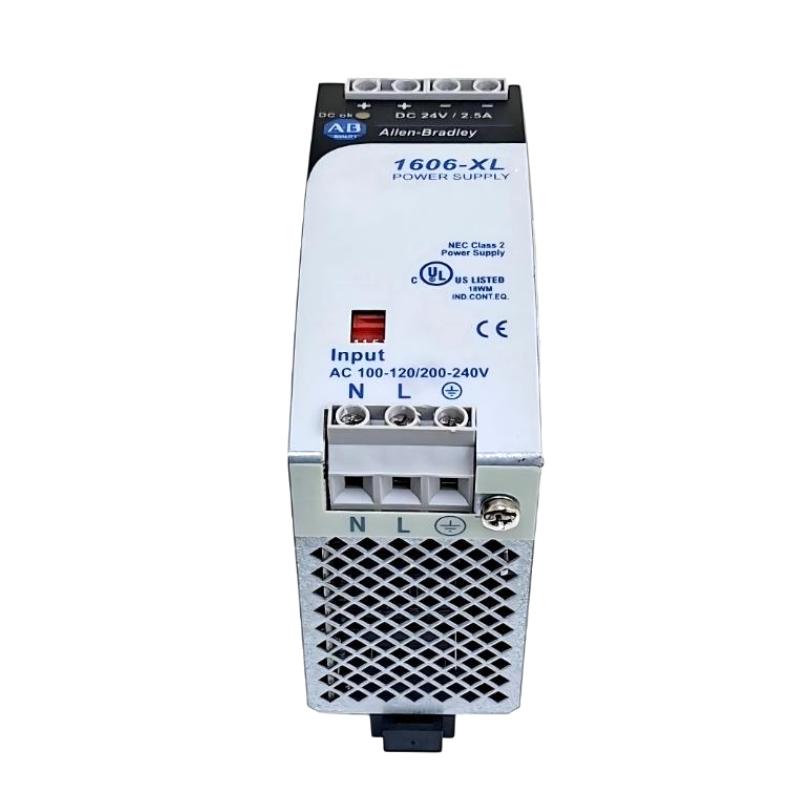
Table of Contents
- Allen Bradley 1606-XL60D Power Supply Fault Diagnosis Approach
- Allen Bradley 1606-XL60D Power Supply Fault Symptoms
- Allen Bradley 1606-XL60D Troubleshooting Logic
- Allen Bradley 1606-XL60D Electrical Measurements
- Common Allen Bradley 1606-XL60D Power Supply Fault Causes
- Allen Bradley 1606-XL60D Load Isolation Method
- Allen Bradley 1606-XL60D Real Fault Diagnosis Case
- Allen Bradley 1606-XL60D Repair and Recovery Decisions
- Allen Bradley 1606-XL60D Post-Repair Verification
- Allen Bradley 1606-XL60D Troubleshooting FAQ
- Allen Bradley 1606-XL60D Overall Troubleshooting Summary
Allen Bradley 1606-XL60D Power Supply Fault Diagnosis Approach
Allen Bradley 1606-XL60D power supply faults should not be diagnosed from a PLC alarm alone. When a PLC Controller, I/O Module, communication interface, or Sensor unexpectedly goes offline, the correct troubleshooting approach is to determine whether the DC supply is actually failing, whether the distribution circuit is unstable, or whether a downstream load is pulling the supply outside normal operating conditions.
The most useful field question is not “Is the power supply faulty?” but “At which point in the power path does the voltage or current become abnormal?” This changes the troubleshooting process from component replacement to evidence-based Fault Diagnosis.
Allen Bradley 1606-XL60D Power Supply Fault Symptoms
Different electrical problems can produce similar symptoms. A PLC reboot, for example, may be caused by a DC voltage dip lasting only a short period. A multimeter may show a normal value after the event and therefore fail to reveal the original problem.
- PLC Controller unexpectedly restarts.
- Remote I/O modules intermittently disappear.
- Communication devices repeatedly reconnect.
- Sensor signals become unstable when actuators operate.
- DC output falls noticeably when the load increases.
- Protective devices trip during startup.
- The control system becomes unstable after adding new loads.
- Faults occur only when contactors or solenoid valves switch.
Allen Bradley 1606-XL60D Intermittent Fault Pattern
Intermittent faults deserve particular attention. If the system operates correctly for several hours and then produces a PLC reset, do not conclude that the power supply is healthy simply because the voltage is normal during inspection. Reproduce the operating condition that caused the failure whenever possible.
Allen Bradley 1606-XL60D Troubleshooting Logic
A useful troubleshooting sequence is based on fault boundaries. If the power-supply terminals remain stable but the remote PLC distribution voltage falls, the fault boundary is downstream of the supply. If the supply output itself collapses while the input remains stable, attention shifts toward overload, short circuit, thermal behavior, or the supply itself.
The following diagnostic logic can be used as a field reference:
IF input voltage abnormal
    investigate upstream supply and protection

ELSE IF supply output abnormal with load disconnected
    investigate power supply and input conditions

ELSE IF supply output stable without load
    reconnect loads individually

IF output falls when one branch is connected
    isolate that branch

IF output is stable at supply but low at PLC
    inspect distribution wiring and terminals
This method prevents a common maintenance error: replacing the 1606-XL60D before proving that the fault actually follows the power supply.
Allen Bradley 1606-XL60D Electrical Measurements
Measurement is the core of reliable Allen Bradley 1606-XL60D Fault Diagnosis. Start with the input circuit, then move to the supply output, then the distribution bus, and finally the affected PLC Controller or Module.
Allen Bradley 1606-XL60D Voltage Drop Investigation
Suppose the power supply measures 24.0 VDC while the PLC distribution terminal measures 23.1 VDC under load. The 0.9 V difference should not be ignored simply because the PLC remains operational. The next investigation should focus on cable resistance, terminal connections, branch loading, and distribution topology.
Measurements should also be repeated during the actual failure event. A static reading taken after the fault has disappeared may provide little diagnostic value.
Common Allen Bradley 1606-XL60D Power Supply Fault Causes
- Input power instability: upstream voltage disturbances can affect the complete DC control circuit.
- Excessive load: additional I/O, sensors, relays, or interface equipment may increase current beyond the original design assumption.
- Downstream short circuit: a damaged field device or cable can pull down a DC branch.
- Loose terminals: increased contact resistance can create voltage drop and localized heating.
- Poor distribution design: long conductors can produce unacceptable voltage drop.
- Electrical interference: switching inductive loads near sensitive control circuits can cause transient disturbances.
- Thermal conditions: excessive cabinet temperature can affect equipment reliability and should be investigated when faults are time-dependent.
Allen Bradley 1606-XL60D Load Isolation Method
Load isolation is often more informative than immediate replacement. When the DC output becomes abnormal, disconnect non-essential branches according to the site’s approved maintenance procedure and observe whether the supply recovers.
If the output returns to normal after one branch is removed, reconnect the remaining branches individually. This creates a simple cause-and-effect relationship between the electrical measurement and the connected equipment.
Allen Bradley 1606-XL60D Branch-by-Branch Fault Diagnosis
- Record the normal DC voltage before the fault is reproduced.
- Identify all downstream branches supplied by the 1606-XL60D.
- Separate non-essential loads where the system design permits.
- Monitor voltage while reconnecting each branch.
- Check the branch that produces the abnormal voltage or current response.
- Inspect the field wiring and connected device on that branch.
- Restore the System Configuration only after the cause is understood.
Allen Bradley 1606-XL60D Real Fault Diagnosis Case
In one industrial control-panel troubleshooting case, a PLC Controller reported intermittent I/O communication loss several times during a production shift. The first inspection showed that the DC power supply appeared normal. The measured voltage at the supply terminals was approximately 24 VDC, so the power supply was initially considered healthy.
However, the failure was reproduced while several field solenoid circuits were operating. At that moment, the voltage at the remote I/O distribution point dropped from approximately 24 VDC to around 22.6 VDC. The supply terminal voltage changed much less than the remote measurement.
The engineering team then checked the branch wiring rather than replacing the power supply. A high-resistance terminal connection was found in the DC distribution path. Under low load the connection appeared acceptable, but when the solenoid circuits operated, the voltage drop increased enough to disturb the remote I/O equipment.
After the connection was corrected and the distribution circuit was inspected, the communication fault could no longer be reproduced under the same operating sequence.
This case demonstrates why Troubleshooting should follow the physical power path. A normal measurement at the power-supply terminals does not prove that every connected Module is receiving stable DC voltage.
Allen Bradley 1606-XL60D Repair and Recovery Decisions
Repair decisions should be based on measured evidence. If the input supply is correct, the 1606-XL60D output remains stable under a verified load, and the abnormal voltage is found in downstream wiring, replacing the power supply is unlikely to solve the problem.
Conversely, if the input conditions are correct and the output remains abnormal with the downstream load appropriately isolated, the power supply becomes a stronger fault candidate. At that point, follow the site’s maintenance and equipment-replacement procedure rather than attempting unauthorized internal component repair.
Allen Bradley 1606-XL60D Recovery Considerations
- Do not bypass protective devices to keep production running.
- Do not reconnect a suspected short circuit repeatedly without investigation.
- Verify polarity before restoring DC loads.
- Inspect terminals after thermal or overload events.
- Record the original fault measurements before replacing equipment.
- Confirm stable operation after restoration rather than accepting an immediate restart as proof of repair.
Allen Bradley 1606-XL60D Post-Repair Verification
After corrective work, the system should be tested under the same operating conditions that originally produced the fault. This is particularly important for intermittent power faults.
The PLC Controller should remain online while the expected I/O loads operate. Communication should be monitored during switching events, and the DC voltage should be checked at both the power supply and important remote distribution points.
Allen Bradley 1606-XL60D Troubleshooting Verification Data
- Input voltage before and during operation.
- DC output voltage at the 1606-XL60D.
- DC voltage at the affected load.
- Voltage response during inductive-load switching.
- PLC Controller operating status.
- I/O Module communication status.
- Any recurrence of the original fault code or symptom.
A good repair record should explain not only what component was changed but why the component was identified as the fault source. This makes future maintenance much more efficient.
Allen Bradley 1606-XL60D Troubleshooting FAQ
Why does the Allen Bradley 1606-XL60D appear normal but the PLC still resets?
The disturbance may occur downstream of the power supply or may be too brief for a conventional multimeter to capture. Check the voltage at the PLC and remote I/O during the actual failure condition.
What is the fastest way to distinguish an overload from a wiring fault?
Compare the supply behavior with different load branches isolated. If removing one branch restores stable output, investigate that branch for excessive current, short circuits, damaged devices, or wiring problems.
Can a loose terminal cause Allen Bradley 1606-XL60D communication faults?
Yes. A high-resistance connection can create voltage drop during increased current demand. The resulting DC disturbance may appear to the control engineer as a communication or I/O fault rather than a power-distribution fault.
Should voltage be measured only at the power supply?
No. For meaningful Fault Diagnosis, measurements should be compared at the power-supply terminals, distribution points, and affected PLC, Module, or field device.
When should an Allen Bradley 1606-XL60D be considered the probable failed component?
The power supply becomes a stronger candidate when the input circuit is verified, downstream faults are isolated, and the supply output remains abnormal under a suitable test condition. The replacement decision should then follow the site’s maintenance procedure.
Allen Bradley 1606-XL60D Overall Troubleshooting Summary
Effective Allen Bradley 1606-XL60D Troubleshooting is based on measurement, isolation, and repeatable evidence. A PLC Controller reset or Module communication fault does not automatically mean that the power supply has failed. The engineer should establish where the abnormal voltage, current, or connection condition actually occurs.
The most reliable Fault Diagnosis method is to compare the electrical condition at the source with the condition at the affected load, reproduce the failure when possible, isolate branches systematically, and verify the correction under the original operating conditions.
For industrial automation systems, this approach reduces unnecessary component replacement and provides a clearer technical record of the fault. Proper System Configuration, disciplined Troubleshooting, and measurement-based commissioning together provide the foundation for reliable operation of the Allen Bradley 1606-XL60D power circuit.