

ProductPRODUCT
Featured products



Contact Us
- GE
- DS215UDSAG1AZZ01A
- Relay Board
- USA
- 180 × 100 × 30 mm
- 0.64 kg
- Xiamen, China
- New & In Stock
- T/T, PayPal, Western Union
- 1 Year
- 1-3 Working Days
- DHL, UPS, TNT, FedEx and EMS.
- 24-Hour Service
- COO
- 58
Our advantage

Global Logistics
We have a 10-year logistics and express cooperation agreement, so our products can be shipped to any place in the world.

Brand new and original
Our products are imported in bulk from the place of origin. Because of the cooperative relationship, our products are all original and 100% new.

24-hour service
We provide 7*24 hours service to our customers. We will be there whenever you need us.

Price advantage
All our products are priced very favorably because we have our own warehouse and supply.
| Company Information | |||
| [email protected] | |||
| Mobile | +8615980777398 | ||
| +8615980777398 | |||
| 15980777398 |
Product Overview
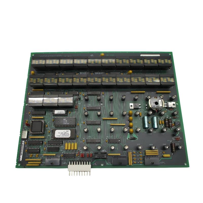
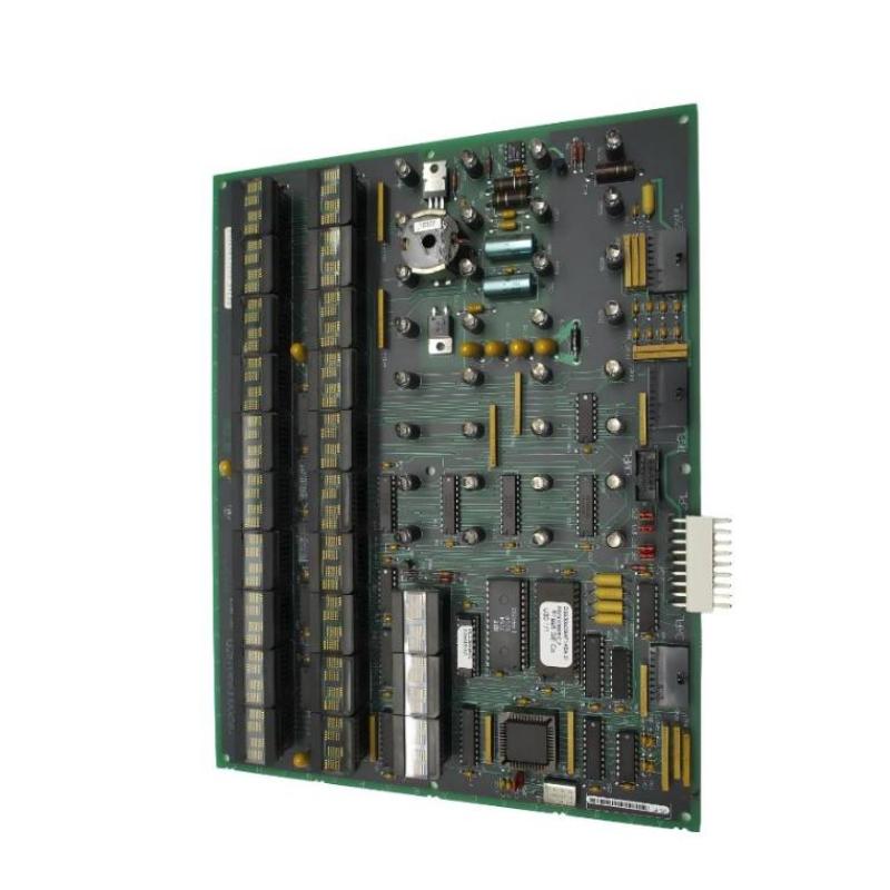
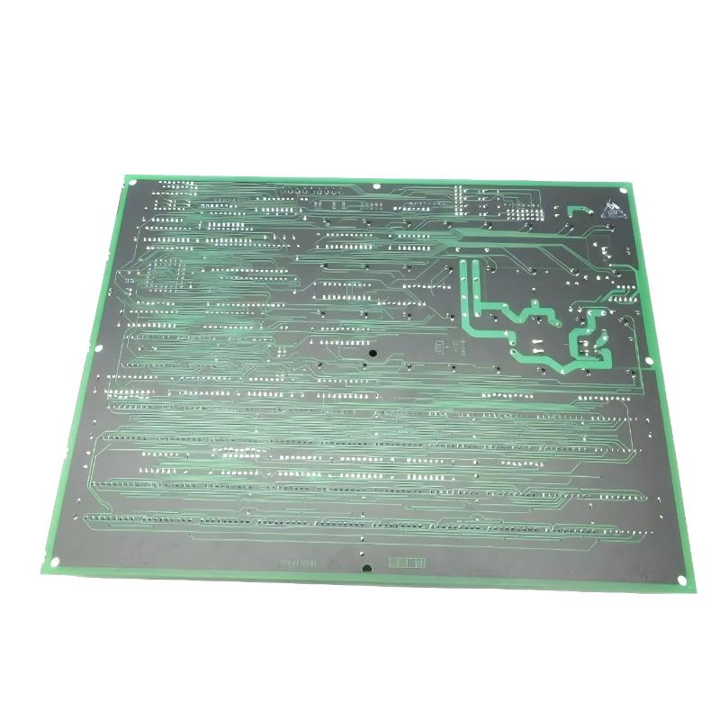
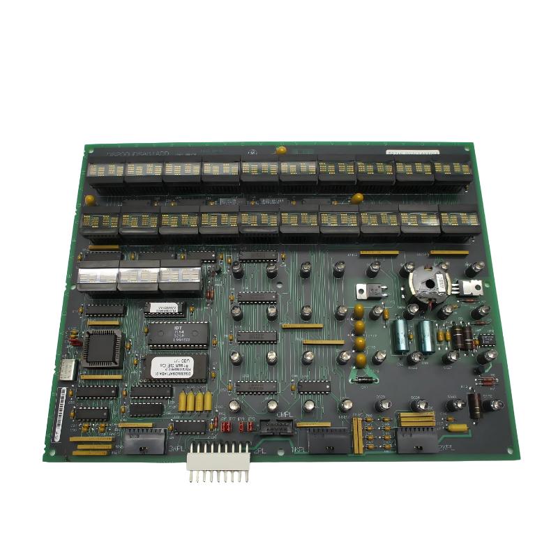
The GE DS215UDSAG1AZZ01A is a UDSAG1 circuit board and firmware assembly associated with GE turbine control equipment. It belongs to the GE Mark V DS200 family and is closely associated with the EX2000 excitation control platform. The board combines dedicated control electronics with firmware used to execute application-specific control functions within the turbine excitation system.
Although the product may sometimes be described in spare-parts listings as a relay or control-related board, its more specific functional identity is a UDSAG1 circuit board with firmware. It is therefore important to distinguish it from a conventional relay output board. The board contains processing hardware, firmware memory, status indication circuitry, and interfaces for exchanging signals with other components in the control system.
The DS215UDSAG1AZZ01A is designed for use in industrial turbine control environments where reliable processing and execution of predefined control instructions are required. It can participate in the management of excitation-related functions and communication with other control hardware.
The board contains a microprocessor-based control architecture and programmable memory devices. The firmware stored on the board provides the instruction set required for the specific application configuration. Because firmware compatibility is directly related to system operation, the complete board identification should be checked before replacement.
The specified physical dimensions of the product are 180 × 100 × 30 mm, and the specified weight is 0.64 kg.
As a legacy industrial control component, the DS215UDSAG1AZZ01A is particularly relevant to maintenance, repair, modernization, and spare-parts management for existing GE turbine control installations.
Technical Specifications
| Parameter | Details |
|---|---|
| Manufacturer | GE General Electric |
| Model | DS215UDSAG1AZZ01A |
| Functional Board | UDSAG1 |
| Product Type | Firmware Control Board / Circuit Board |
| Series | GE Mark V DS200 |
| Associated Platform | GE EX2000 Excitation Control |
| Functional Acronym | UDSA |
| Assembly Type | DS215 Special Assembly |
| Primary Function | Control processing and firmware execution |
| Processor Architecture | Microprocessor-based control |
| Memory | EPROM-based firmware storage |
| Status Indication | LED and display-based diagnostics |
| Application | Turbine excitation and industrial control |
| Installation | Control cabinet / control system rack |
| Dimensions | 180 × 100 × 30 mm |
| Weight | 0.64 kg |
| Industrial Environment | Power generation and turbine automation |
| Service Application | Maintenance, replacement and system restoration |
What Is the GE DS215UDSAG1AZZ01A?
The GE DS215UDSAG1AZZ01A is a specialized GE control board incorporating the UDSAG1 hardware and associated firmware. It is designed to perform application-specific processing within GE turbine control and excitation systems.
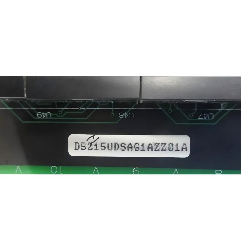
The “DS215” designation identifies the special assembly family, while “UDSAG1” identifies the functional board family. The remaining suffix characters identify the specific hardware and firmware configuration.
This distinction is important when purchasing or replacing the board. Two boards that appear similar may have different firmware configurations and therefore may not perform the same control functions.
The board is best understood as part of the control-processing layer rather than simply as a switching or relay device.
Function and Working Principle
The DS215UDSAG1AZZ01A operates as a programmable control-processing board. Its microprocessor executes instructions stored in the board’s firmware memory and processes information received from other components of the control system.
A simplified operating sequence can be represented as:
Input Signals → UDSAG1 Processing Board → Firmware Logic → Control Output / System Communication
The board receives electrical signals through connected cables and interfaces. The microprocessor processes these signals according to the application firmware and generates the appropriate control information for other parts of the system.
The firmware is an important part of the board’s functionality. It defines how the processor interprets inputs, performs calculations, manages control logic, and communicates the resulting information.
Typical functions associated with this type of control architecture can include:
- Signal processing
- Control logic execution
- Excitation-related control functions
- System status monitoring
- Inter-board communication
- Fault indication
- Diagnostic processing
- Control output generation
- System sequencing
- Application-specific firmware execution
The exact control functions depend on the host turbine and the specific EX2000 system configuration.
Role in GE EX2000 Excitation Control
The DS215UDSAG1AZZ01A is associated with GE’s EX2000 excitation control environment. Excitation control is an important part of generator operation because the excitation system controls the magnetic field of the generator.
By controlling excitation-related parameters, the overall system can influence generator voltage, reactive power behavior, and other electrical operating conditions.
A simplified excitation control architecture can be represented as:
Generator Measurements → Control Processing → Excitation Control → Exciter → Generator Field
The DS215UDSAG1AZZ01A forms part of the electronic control layer within this larger architecture.
The board should therefore be considered together with the associated excitation control hardware, power supplies, interface boards, feedback circuits, and operator-control components.
Firmware and Control Logic
One of the most important characteristics of the DS215UDSAG1AZZ01A is the presence of application firmware.
Firmware differs from ordinary configuration data because it contains the instructions that the microprocessor uses to perform its assigned control functions.
The board’s firmware can determine how the processor:
- Interprets incoming signals
- Processes measurement information
- Executes control algorithms
- Generates system outputs
- Handles abnormal operating conditions
- Communicates with other control boards
- Provides diagnostic information
This is why firmware compatibility must be considered when selecting a replacement board.
A replacement board with different firmware may be physically compatible but functionally unsuitable for a particular application. For legacy turbine control systems, matching the complete board and firmware identification is therefore highly recommended.
Processor and Memory Architecture
The DS215UDSAG1AZZ01A uses a microprocessor-based architecture. The processing hardware executes instructions stored in programmable memory devices associated with the board.
Earlier GE industrial control platforms commonly used dedicated processors and EPROM devices to store application firmware. This architecture allowed the control logic to remain associated with a specific hardware configuration.
The relationship can be simplified as:
EPROM Firmware → Microprocessor → Signal Processing → Control Functions
During operation, the processor retrieves instructions from the firmware memory and executes them according to the incoming system conditions.
Because the firmware is directly involved in system behavior, firmware devices should be handled carefully during maintenance and replacement.
Diagnostic Indicators and Displays
Visual diagnostic information is another important characteristic of the board.
LED indicators and display devices can provide maintenance personnel with information about board operation, system status, and potential fault conditions.
Depending on the configuration, diagnostic indicators can help technicians determine whether:
- The board is receiving power
- The processor is operating
- Control logic is executing
- Communication is active
- A fault condition has occurred
- A particular control sequence is active
Diagnostic indicators should be interpreted together with the overall system condition. A single illuminated or inactive LED should not automatically be treated as proof of a board failure.
Role in Industrial Control Systems
The DS215UDSAG1AZZ01A operates within a larger industrial control architecture. It does not normally function as an independent controller.
A typical system can contain:
- Control processors
- Excitation control boards
- Analog I/O boards
- Digital I/O boards
- Relay interfaces
- Power supply boards
- Terminal boards
- Feedback circuits
- Communication interfaces
- Operator interfaces
The UDSAG1 board works together with these components to provide coordinated control.
In a turbine or generator application, information can move through several stages before a final control action is generated.
Field Measurement → Interface Board → Control Processor → UDSAG1 Firmware Logic → Output Interface → Excitation Equipment
This layered architecture allows complex control algorithms to be implemented using multiple dedicated boards.
Industrial Applications
The GE DS215UDSAG1AZZ01A is associated with industrial turbine and excitation control applications.
Typical application environments include:
- Gas turbine power plants
- Steam turbine power plants
- Combined-cycle power generation
- Industrial generator systems
- Utility power generation
- Cogeneration plants
- Large rotating electrical equipment
- Industrial excitation systems
- Legacy GE turbine control systems
- EX2000-based control installations
In these environments, reliable control processing is important because an excitation-system malfunction can affect generator voltage regulation and overall plant operation.
Compatible System Components
The DS215UDSAG1AZZ01A should be considered part of a complete control-system architecture. The exact associated components depend on the specific GE installation.
| Component | Type | Typical Function |
|---|---|---|
| DS215UDSAG1AZZ01A | Firmware Control Board | Control processing and firmware execution |
| DS215UDSAG1 | UDSAG1 Board | Base control hardware |
| EX2000 Control Hardware | Excitation Controller | Generator excitation management |
| Analog I/O Boards | Signal Interface | Analog measurement processing |
| Digital I/O Boards | Signal Interface | Discrete signal processing |
| Relay Output Boards | Output Interface | Switching and control outputs |
| Terminal Boards | Field Interface | Field wiring termination |
| Power Supply Boards | Power Hardware | Provides regulated control power |
| Feedback Devices | Measurement Hardware | Provides system feedback |
| Generator Sensors | Instrumentation | Provides electrical measurements |
| Operator Interface | HMI | Monitoring and system operation |
These components can form a complete signal-processing and control chain around the UDSAG1 board.
Installation and System Integration
Installation of the DS215UDSAG1AZZ01A should be performed by qualified industrial control personnel familiar with GE turbine and excitation systems.
Because this is a firmware-containing control board, replacement requires more than simply checking physical dimensions.
A general replacement procedure includes:
- Place the turbine and excitation control system into the approved maintenance condition.
- Follow site lockout and electrical isolation procedures.
- Verify that the relevant control power has been removed.
- Identify the existing UDSAG1 board.
- Record the complete DS215UDSAG1AZZ01A part number.
- Record the board location and rack position.
- Document all cable and connector positions.
- Record diagnostic indicator conditions before removal.
- Compare the replacement board identification.
- Verify firmware compatibility.
- Inspect the replacement board for mechanical damage.
- Check connectors and cable interfaces.
- Install the board in the correct position.
- Reconnect all cables carefully.
- Verify connector orientation.
- Check grounding and shielding.
- Restore control power according to the approved procedure.
- Observe board diagnostic indicators.
- Verify processor operation.
- Check communication with associated control hardware.
- Verify excitation-related measurements.
- Complete system commissioning tests.
The actual commissioning sequence should follow the configuration and approved maintenance procedure of the individual turbine control system.
Firmware Compatibility During Replacement
Firmware compatibility is one of the most important considerations when replacing a DS215UDSAG1AZZ01A.
The replacement board should have the appropriate firmware configuration for the application. If firmware devices are transferred from the original board, they must be handled carefully to prevent mechanical or electrostatic damage.
Before replacement, technicians should compare:
- Complete part number
- Firmware identification
- Board revision
- EPROM configuration
- Connector arrangement
- Control-system configuration
- Application requirements
Firmware mismatch can result in incorrect system behavior even when the replacement board appears electrically and mechanically similar.
Electrostatic Discharge Protection
The DS215UDSAG1AZZ01A contains sensitive electronic components and should be treated as an electrostatic-sensitive device.
During maintenance, technicians should use appropriate ESD protection and avoid touching exposed electronic contacts unnecessarily.
Recommended precautions include:
- Use an approved ESD wrist strap
- Work on an ESD-safe surface
- Avoid touching connector contacts
- Handle circuit boards by their edges
- Keep boards inside protective packaging when not installed
- Avoid placing the PCB on conductive or contaminated surfaces
- Protect firmware memory devices from mechanical damage
Good ESD practices can significantly reduce the risk of latent electronic damage during replacement.
Maintenance and Troubleshooting
Troubleshooting the DS215UDSAG1AZZ01A should begin with a determination of whether the problem is limited to the board or originates elsewhere in the control system.
| Observed Condition | Possible Area to Check |
|---|---|
| Board does not start | Control power, power supply, connector or board hardware |
| No diagnostic indication | Power supply, processor, display circuit or board hardware |
| Unexpected diagnostic indication | Firmware, input signals, communication or board configuration |
| Communication failure | Cables, connectors, interface board or processor |
| Incorrect control behavior | Firmware, configuration, input data or board hardware |
| Intermittent operation | Connector, cable, power supply or electronic components |
| Excitation control abnormal | Control logic, feedback signals, interface boards or excitation equipment |
| Multiple system alarms | Common power, communication or control-system problem |
A useful diagnostic sequence is:
Power Supply → Board Status → Processor → Firmware → Communication → Input Signals → Output Signals → Excitation Equipment
This approach helps technicians avoid replacing the board unnecessarily.
Power Supply Troubleshooting
If the board does not power up, the first step should be verification of the incoming control power.
Possible causes include:
- Failed control power supply
- Open protection device
- Loose power connection
- Incorrect voltage
- Grounding problem
- Board-level power circuit failure
If the expected supply voltage is not available at the board, replacing the UDSAG1 assembly may not correct the problem.
Communication Troubleshooting
Control boards rarely operate in isolation. Communication with other boards is therefore an important diagnostic area.
If communication is lost, technicians should inspect:
- Ribbon cables
- Board connectors
- Communication interface circuits
- Associated control boards
- Power supplies
- System configuration
A loose or incorrectly installed cable can produce symptoms that resemble processor or firmware failure.
Firmware-Related Faults
Firmware-related problems can be more difficult to diagnose than simple wiring faults.
Possible indicators include:
- Unexpected processor behavior
- Abnormal diagnostic displays
- Incorrect control sequences
- Communication abnormalities
- Failure to complete initialization
- Repeated system alarms
When firmware is suspected, the complete board and firmware identification should be verified before any replacement is attempted.
For legacy systems, firmware configuration can be closely tied to the original turbine application. A generic board with a similar physical appearance should not automatically be considered a valid replacement.
Common Causes of DS215UDSAG1AZZ01A Problems
Potential causes of faults associated with this board include:
- Control power failure
- Connector problems
- Ribbon cable damage
- Firmware incompatibility
- EPROM failure
- Processor malfunction
- Component aging
- Electrical noise
- Grounding problems
- Communication failure
- Incorrect configuration
- ESD damage
- Environmental stress
A systematic diagnostic process should be used to determine the actual failure mechanism.
Replacement Considerations
When sourcing a replacement DS215UDSAG1AZZ01A, the complete identification should be verified rather than relying only on the description “GE relay board.”
Important identification information includes:
- DS215UDSAG1AZZ01A
- UDSAG1 functional designation
- Firmware configuration
- Board revision
- EX2000 application
- Connector arrangement
- EPROM configuration
- Control-system location
- Associated control hardware
The exact firmware configuration is particularly important because the board’s control behavior depends on the firmware installed in the memory devices.
For this reason, the complete part number should be matched whenever possible.
Recommended Alternative Models
The following GE models are related control, firmware, power, or I/O products that may be useful for comparison and spare-parts planning. They should not automatically be treated as direct replacements for the DS215UDSAG1AZZ01A.
| Model | Type | Key Feature | Application |
|---|---|---|---|
| DS215UDSAG1AZZ01A | UDSAG1 Firmware Board | Control processing and firmware | GE EX2000 / turbine control |
| DS215UDSAG1A | UDSAG1 Control Board | Base UDSAG1 hardware | GE turbine excitation |
| DS215UPLAG1AZZ01A | Control / Firmware Board | UPLAG1 firmware configuration | GE Mark V control systems |
| DS215UPLAG1BZZ01A | Power / Control Board | UPLAG1 function | GE Mark V systems |
| DS215UCIBG3AZZ01A | Control Board | UCIB control architecture | GE turbine control |
| DS200TCRAG1A | Relay Output Board | Relay output interface | GE Mark V control |
| DS200TCPSG1A | DC Input Power Supply Board | Control power interface | GE Mark V systems |
| DS200TCQAG1B | Analog I/O Board | Analog signal processing | GE turbine control |
Replacement recommendation: The preferred replacement should be an exact match for DS215UDSAG1AZZ01A, including its UDSAG1 hardware and compatible firmware configuration. A relay output board, analog I/O board, or another firmware board should not be substituted solely because its physical dimensions or general application appear similar.
Key Advantages
- Designed for GE industrial turbine control applications
- Associated with the GE EX2000 excitation control platform
- Combines control electronics with application firmware
- Provides microprocessor-based control processing
- Supports application-specific firmware execution
- Provides visual diagnostic information
- Supports communication with associated control hardware
- Suitable for legacy GE turbine maintenance
- Useful for replacement and spare-parts planning
- Supports continued operation of established industrial control systems
Technical FAQs
What is the GE DS215UDSAG1AZZ01A?
The GE DS215UDSAG1AZZ01A is a UDSAG1 circuit board and firmware assembly associated with GE turbine and EX2000 excitation control applications.
Is DS215UDSAG1AZZ01A a relay board?
It is more accurately identified as a UDSAG1 firmware and control board rather than a conventional relay output board. Relay output functions belong to other GE Mark V board families.
What is the main function of the DS215UDSAG1AZZ01A?
Its primary role is to execute application-specific firmware and perform control processing within the associated GE turbine or excitation control architecture.
What system is the DS215UDSAG1AZZ01A associated with?
The board is associated with GE Mark V control hardware and the EX2000 excitation control environment.
What are the specified dimensions?
The specified dimensions for this product are 180 × 100 × 30 mm.
What is the specified weight?
The specified weight is 0.64 kg.
Why is firmware important for this board?
The firmware contains the instructions executed by the board’s processor. It determines how incoming information is processed and how the board performs its application-specific control functions.
What components work with the UDSAG1 board?
Depending on the installation, associated components can include EX2000 excitation hardware, analog I/O boards, digital I/O boards, relay interfaces, terminal boards, power supply boards, feedback devices, generator sensors, communication interfaces, and operator-interface equipment.
What can cause a DS215UDSAG1AZZ01A fault?
Possible causes include power problems, damaged connectors, cable faults, firmware incompatibility, EPROM problems, processor faults, communication failures, environmental stress, grounding problems, and component aging.
Can a relay board directly replace DS215UDSAG1AZZ01A?
No. A relay output board and a UDSAG1 firmware control board perform different functions. Replacement should be based on the complete system architecture and exact part-number compatibility.
Can another DS215 board be used as a replacement?
Not automatically. DS215 boards can perform very different functions. The functional designation, firmware configuration, hardware revision, connectors, and system application must all be verified before substitution.
How should the board be handled during replacement?
The board should be treated as an electrostatic-sensitive electronic assembly. Qualified technicians should use appropriate ESD protection, handle the PCB by its edges, and avoid touching connector contacts or exposed electronic components.
Why should the complete part number be checked?
The complete part number identifies the specific board assembly and configuration. This is particularly important for legacy GE systems where firmware and hardware revisions can be closely associated with the turbine application.
Conclusion
The GE DS215UDSAG1AZZ01A UDSAG1 Firmware Control Board is a specialized electronic control assembly associated with GE Mark V and EX2000 turbine excitation systems. Its function is substantially different from that of a conventional relay output board. The board combines control-processing hardware with application-specific firmware to execute dedicated system instructions and communicate with other components of the industrial control architecture.
The board is particularly important in legacy turbine control environments where the original GE control architecture remains in service. Its microprocessor-based processing, firmware memory, diagnostic indicators, and system interfaces allow it to participate in complex control and excitation functions.
The specified physical dimensions are 180 × 100 × 30 mm, while the specified weight is 0.64 kg. For maintenance and replacement purposes, the complete identification DS215UDSAG1AZZ01A should be retained.
Because firmware is an integral part of the board’s functionality, replacement should not be based solely on physical appearance or general product descriptions. Hardware revision, firmware configuration, connector arrangement, system location, and the associated EX2000 application should all be verified.
For engineers, maintenance technicians, and spare-parts managers working with GE turbine automation equipment, accurate identification of the DS215UDSAG1AZZ01A can help reduce replacement errors and improve maintenance efficiency. When correctly matched to the surrounding control architecture, this UDSAG1 firmware control board provides an important processing element for established GE turbine and excitation control systems.