

ProductPRODUCT
Featured products



Contact Us
- GE
- IC640WMI610
- Interface Board
- USA
- 330 × 105 × 25 mm
- 0.36 kg
- Xiamen, China
- New & In Stock
- T/T, PayPal, Western Union
- 1 Year
- 1-3 Working Days
- DHL, UPS, TNT, FedEx and EMS.
- 24-Hour Service
- COO
- 54
Our advantage

Global Logistics
We have a 10-year logistics and express cooperation agreement, so our products can be shipped to any place in the world.

Brand new and original
Our products are imported in bulk from the place of origin. Because of the cooperative relationship, our products are all original and 100% new.

24-hour service
We provide 7*24 hours service to our customers. We will be there whenever you need us.

Price advantage
All our products are priced very favorably because we have our own warehouse and supply.
| Company Information | |||
| [email protected] | |||
| Mobile | +8615980777398 | ||
| +8615980777398 | |||
| 15980777398 |
Product Overview
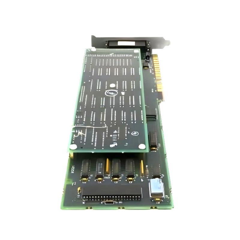
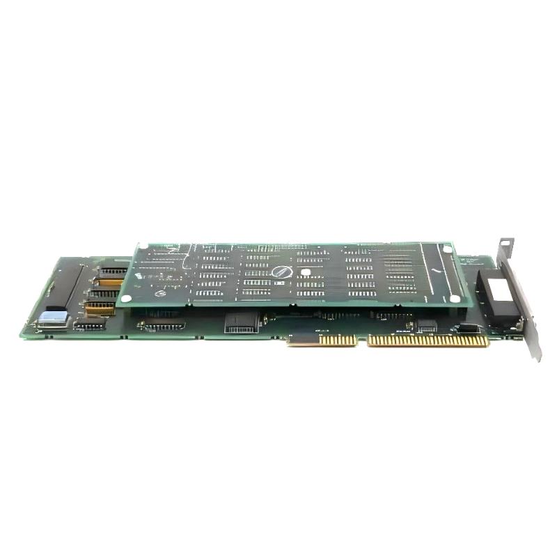
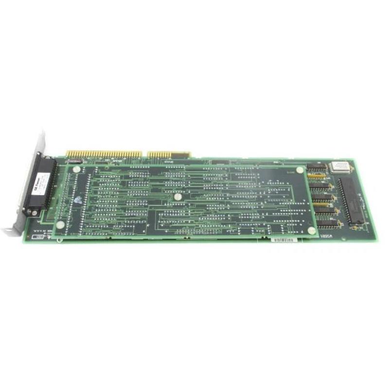
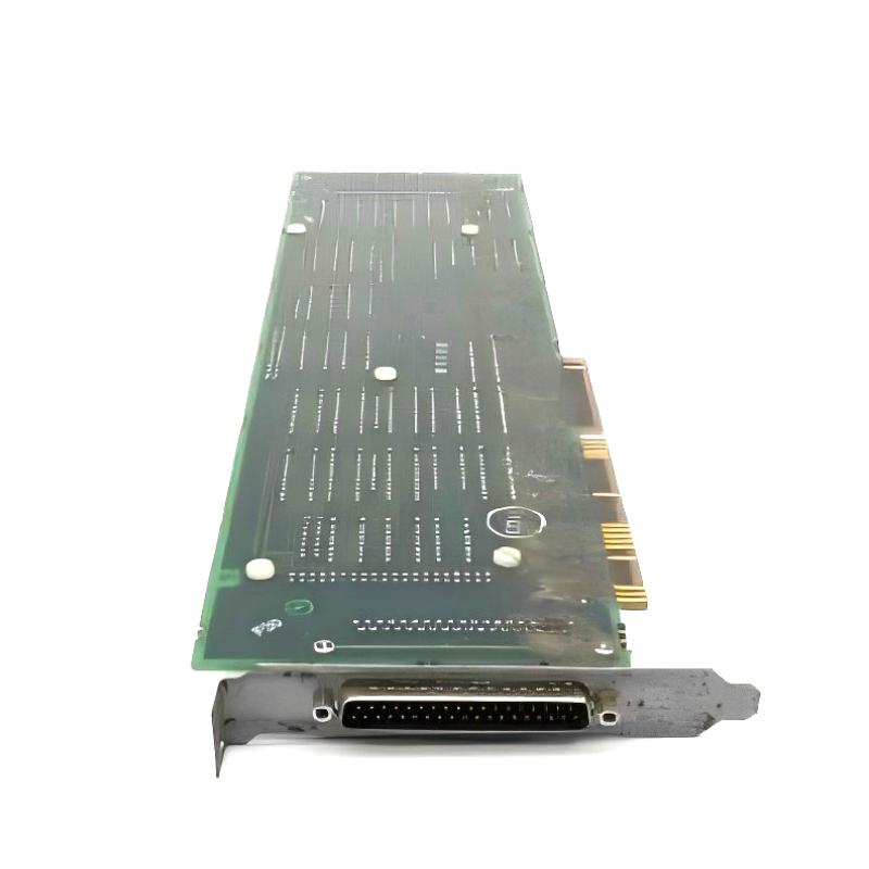
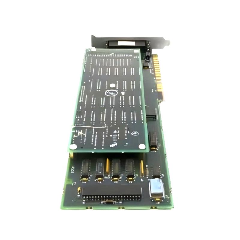
The GE IC640WMI610 Series Six Interface Board is an interface component used within the GE Series Six PLC platform. It belongs to the system interconnection layer, where compatible control-system hardware can exchange signals or information through the appropriate interface architecture.
Unlike a conventional discrete input or output module, the IC640WMI610 is not primarily used to collect individual field signals or directly drive field actuators. Its function is associated with connecting sections of the control system so that the overall PLC architecture can operate as intended.
For maintenance engineers working with legacy GE Series Six installations, the interface board can become an important replacement component when an established control system develops an interface-related fault. Troubleshooting should include the board, connected cables, connectors, associated hardware, and system power rather than treating the board as an isolated device.
The IC640WMI610 is therefore most relevant in applications where maintaining the original Series Six architecture is preferable to replacing an entire control system.
Technical Specifications
| Parameter | Specification |
|---|---|
| Manufacturer | GE |
| Model | IC640WMI610 |
| Product Family | Series Six |
| Product Type | Interface Board |
| Primary Function | System Hardware Interface |
| System Role | Interface / Interconnection Layer |
| Application | Industrial Automation / PLC Systems |
| Installation | Series Six Control System |
| Dimensions | 330 × 105 × 25 mm |
| Weight | 0.36 kg |
Product Features
The IC640WMI610 is suited to the hardware integration requirements of GE Series Six PLC installations.
Key characteristics include:
- GE Series Six interface board
- Model IC640WMI610
- Intended for system-level hardware interconnection
- Suitable for legacy PLC control systems
- Supports compatible Series Six hardware
- Useful for established industrial automation installations
- Suitable for maintenance and replacement work
- Interfaces with associated system hardware and wiring
- Requires correct installation within the applicable system architecture
- Suitable for long-service industrial control environments
For replacement applications, identifying the exact board position and connected equipment is important. Interface hardware can have system-specific relationships that are not apparent from the board itself.
Working Principle
The IC640WMI610 functions within the interface path of the Series Six control architecture.
A simplified relationship can be represented as:
Series Six Control Hardware → IC640WMI610 → Interface Path → Connected System Hardware
The board provides the required interface between compatible sections of the control system. Depending on the surrounding architecture, the interface path may involve dedicated connections, associated system hardware, and communication or signal wiring.
This differs from the operation of a standard input module. An input card is concerned with bringing field conditions into the PLC, while an interface board is concerned with the connection between system-level hardware.
When troubleshooting an interface problem, engineers should therefore work through the complete signal path. If one section of the system is unavailable, the investigation should include the connected equipment, cabling, connectors, power conditions, and board installation before determining that the IC640WMI610 itself has failed.
Role in a PLC Control Architecture
The IC640WMI610 occupies an interface and interconnection layer within a Series Six PLC installation.
A simplified architecture can be viewed as:
Series Six PLC Hardware → Interface Board → Associated System Hardware → Field Control
The board does not replace the PLC CPU, execute application logic, or perform the same task as a field I/O module. Instead, it supports the hardware relationships required for the complete control system to function.
This distinction is useful during maintenance. If the PLC processor is operating normally but an associated hardware section cannot exchange the expected signals, the interface path becomes one of the areas that should be examined.
For legacy systems, this type of structured troubleshooting is especially valuable because control cabinets may contain equipment that has been modified or expanded during many years of operation.
Industrial Applications
The IC640WMI610 is intended for industrial automation installations that continue to use GE Series Six control hardware.
| Application | Typical Use |
|---|---|
| Manufacturing Automation | Maintaining PLC system interfaces |
| Machine Control | Supporting legacy control architectures |
| Process Equipment | Interconnecting control-system hardware |
| Material Handling | Maintaining established PLC installations |
| Packaging Machinery | Supporting existing automation hardware |
| Industrial Production Lines | System-level hardware integration |
| Legacy PLC Systems | Interface-board replacement |
| Plant Maintenance | Extending the service life of existing control equipment |
The actual use depends on the architecture and hardware surrounding the interface board.
Installation and Maintenance
Installation should be performed with the Series Six system configuration clearly identified before the existing board is removed.
For a replacement project, it is good practice to document the board position, connector arrangement, cable identification, and associated hardware first. This is particularly important on older PLC systems where the installed configuration may have been modified after the original commissioning.
Recommended maintenance checks include:
- Confirm the complete IC640WMI610 part number.
- Record the existing board position.
- Identify all connected hardware.
- Document connector and cable locations.
- Inspect connectors for contamination or physical damage.
- Check cable insulation and termination.
- Verify the relevant system power conditions.
- Confirm correct board positioning.
- Inspect the replacement board before installation.
- Ensure connectors are fully seated.
- Check the associated hardware after replacement.
- Monitor system operation during commissioning.
- Review any resulting diagnostic indications.
- Record the final installation configuration.
If an interface-related fault is intermittent, inspect connectors and cables while the system is operating under normal conditions. Mechanical vibration, aging connections, and cable deterioration can produce intermittent symptoms that are easily mistaken for electronic board failure.
Related Components
The IC640WMI610 works as part of a broader Series Six control-system architecture.
| Component | Function |
|---|---|
| GE Series Six CPU | Executes PLC application logic |
| Series Six Rack | Provides the module installation structure |
| Series Six I/O Modules | Interfaces with field signals |
| Interface Board | Connects compatible system hardware |
| Communication / Interface Wiring | Transfers signals between system components |
| Power Supply | Provides operating power |
| Terminal Connections | Provides electrical termination |
| Programming System | Supports PLC configuration and maintenance |
| Field Sensors | Provide process and machine information |
| Output Devices | Receive commands from the control system |
When diagnosing an interface problem, these components should be considered as a complete signal and power path rather than independent devices.
Recommended Related Models
For a GE Series Six installation, related hardware should be selected according to its system position and intended function.
| Model / Product Family | Product Type | Typical Application |
|---|---|---|
| GE IC640WMI610 | Interface Board | Series Six system interconnection |
| GE IC600BF832 | Input Module | Discrete field-input acquisition |
| GE Series Six Input Modules | PLC Input Hardware | Monitoring field signals |
| GE Series Six Output Modules | PLC Output Hardware | Controlling field devices |
| GE Series Six CPU Modules | PLC Controller Hardware | Program execution |
| GE Series Six Rack Components | PLC System Hardware | Module installation and system expansion |
The IC600BF832 and IC640WMI610 serve different functions. The IC600BF832 is an input module for field signal acquisition, while the IC640WMI610 belongs to the system interface layer. Selection should therefore be based on the actual function required rather than physical similarity.
Key Advantages
- GE Series Six interface board.
- Model IC640WMI610.
- Supports system-level hardware interconnection.
- Suitable for legacy GE PLC installations.
- Integrates with compatible Series Six system hardware.
- Useful for maintenance and replacement projects.
- Supports established industrial automation architectures.
- Suitable for manufacturing and process-control environments.
- Helps maintain existing PLC infrastructure without unnecessary system replacement.
- Suitable for long-term service and maintenance applications.
Technical FAQs
When would an IC640WMI610 be investigated as the source of a PLC system fault?
It becomes a candidate when the associated Series Six hardware is powered and otherwise operational but the expected interface between system sections is unavailable or unstable. Before replacing the board, technicians should verify the connected hardware, cables, connectors, and power conditions.
What information should be recorded before removing the existing interface board?
The board location, connector positions, cable identification, associated hardware, and any existing diagnostic condition should be recorded. Photographs of the installed wiring can also be useful when servicing an older cabinet with limited documentation.
Why can an interface-board fault appear to be a communication problem?
An interface board may sit directly within the path through which system hardware exchanges information. If that path is interrupted, the controller or connected equipment may report missing data, unavailable hardware, or communication-related faults even though the actual problem is located at the physical interface.
What is a practical way to verify an IC640WMI610 replacement?
After confirming the correct part number and installation position, verify connector seating and associated wiring before powering the system. Then check whether the previously affected hardware becomes available and whether the original fault condition has cleared. Functional verification should be performed under normal operating conditions rather than relying only on power-up status.