Product Overview
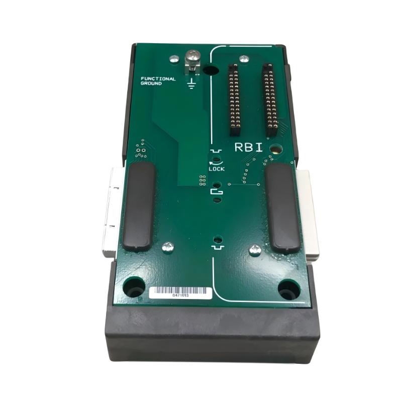
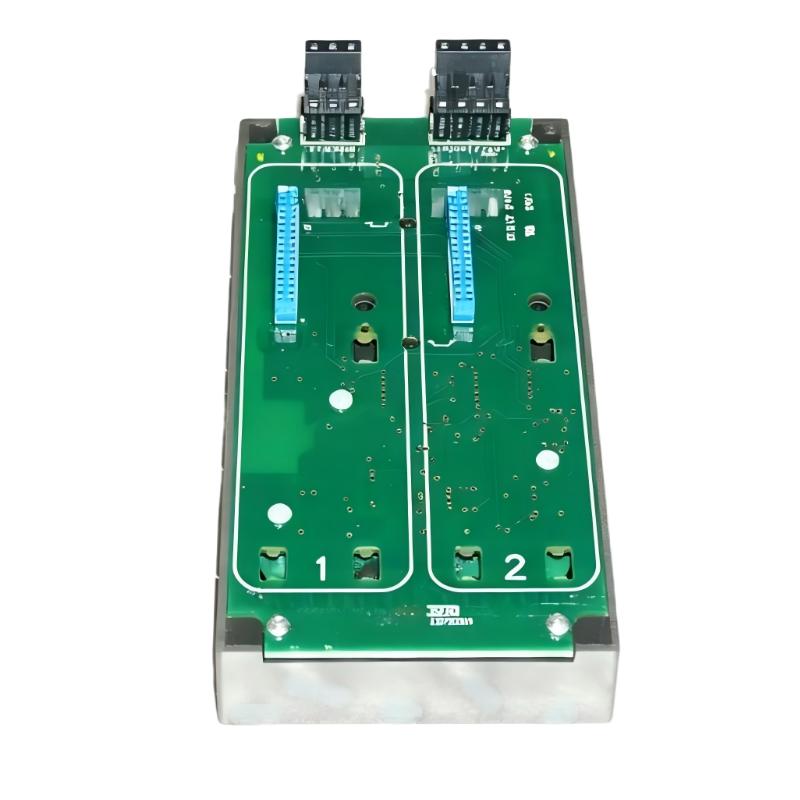
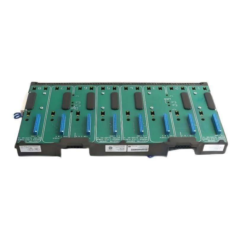
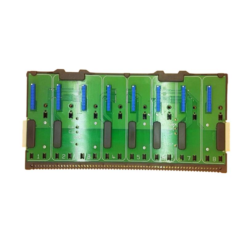
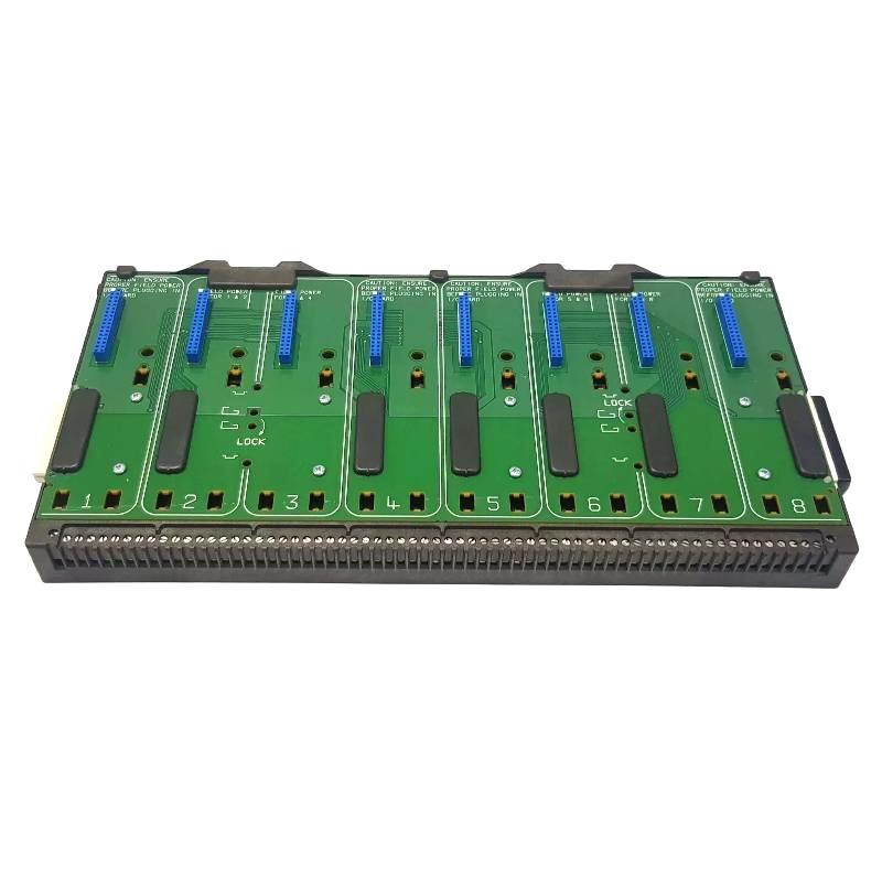
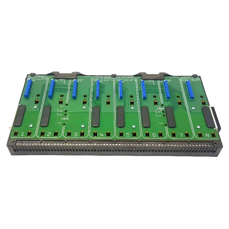
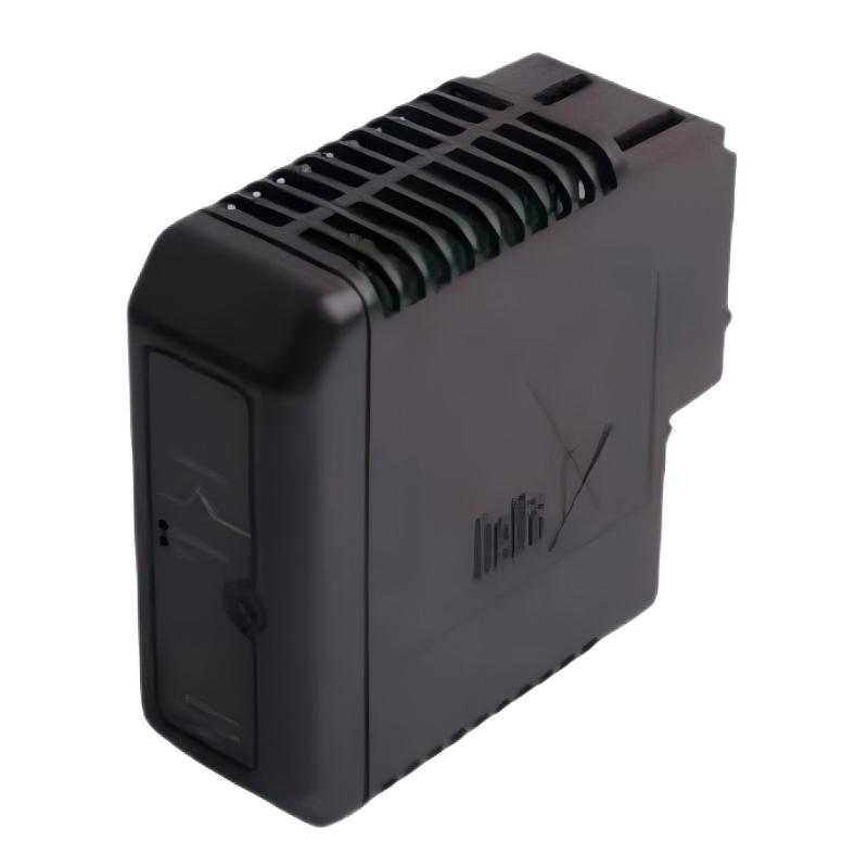
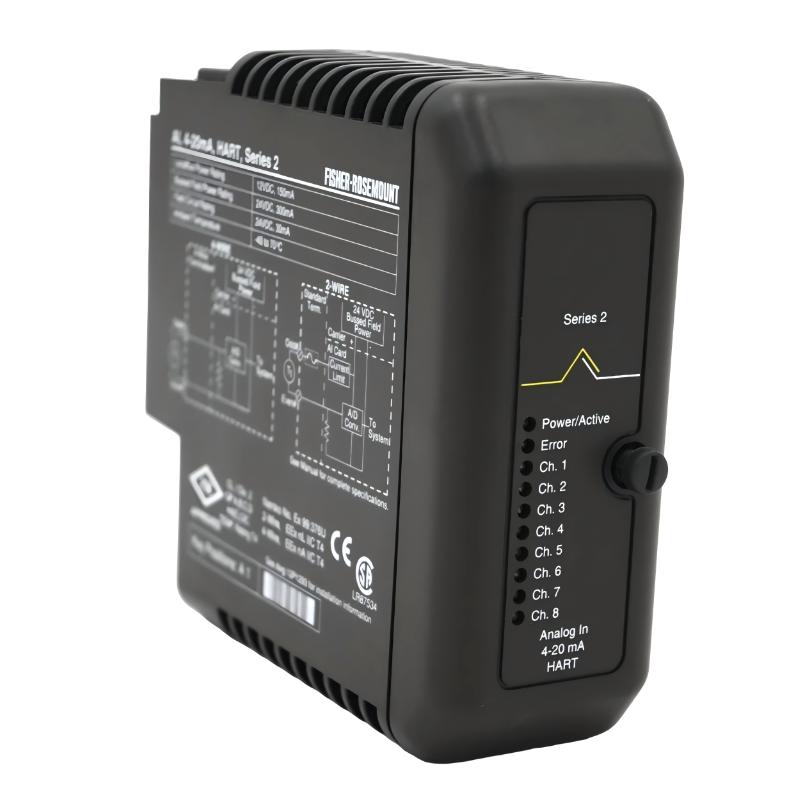
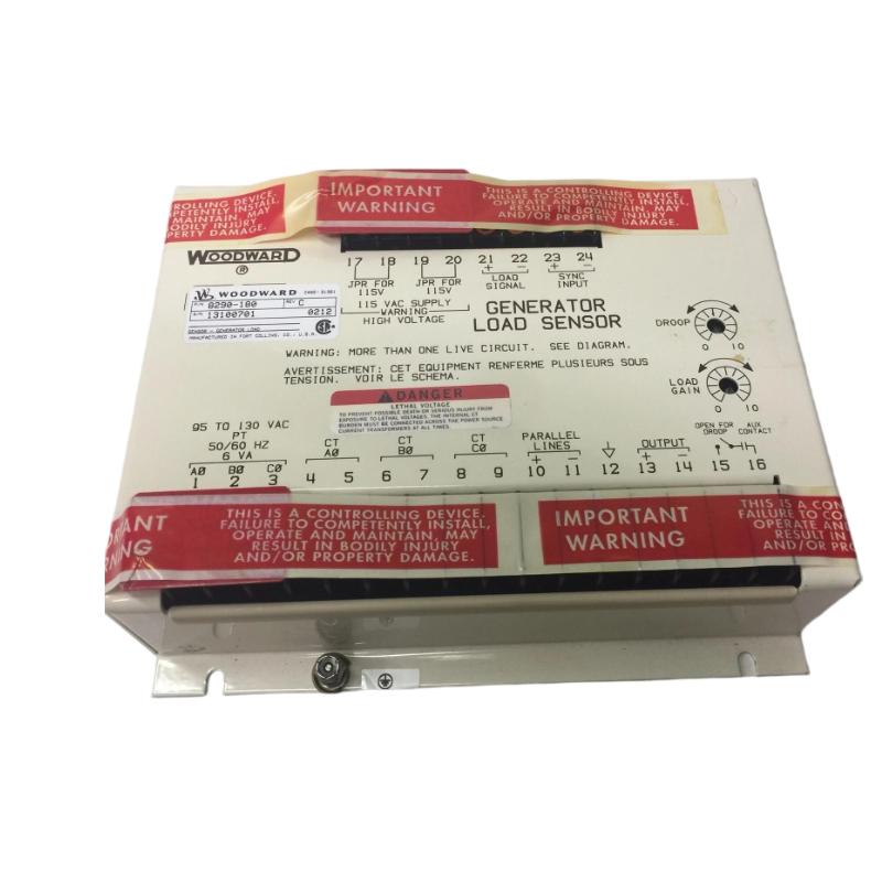
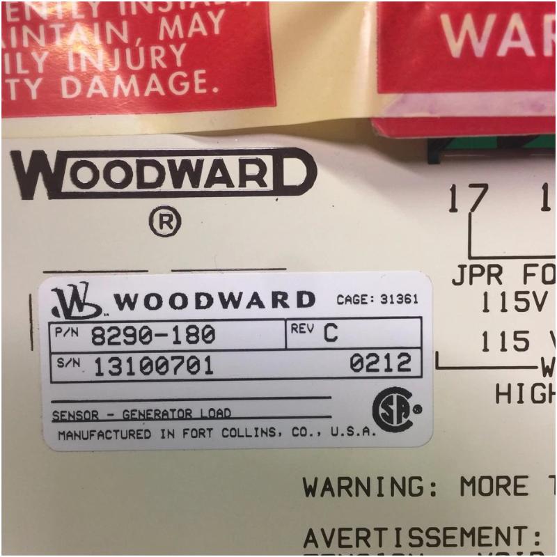
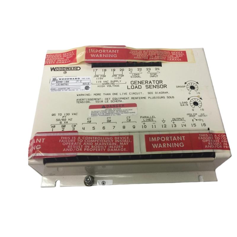
The Woodward 8290-180 Generator Load Sensor is a generator-system measurement component designed to provide load-related information to a compatible control system. Generator load sensing is important in applications where engine or turbine output must respond to changing electrical demand.
In a typical generator control architecture, the load-sensing function provides the controller with information representing generator loading. The control system can then use this information for functions such as load sharing, load-dependent control, operating-limit management, and generator-system coordination.
The supplied physical specifications for the Woodward 8290-180 are 200 × 150 × 80 mm, with a stated weight of 1.8 kg.
Because load measurement can influence generator control decisions, correct electrical connections, signal scaling, calibration, and system configuration are important during installation and commissioning.
Technical Specifications
| Parameter |
Details |
| Manufacturer |
Woodward |
| Model |
8290-180 |
| Product Type |
Generator Load Sensor |
| Main Function |
Generator Load Measurement |
| Application |
Generator and Engine Control Systems |
| Measurement Function |
Electrical Generator Loading |
| Control Role |
Load Feedback |
| Installation |
Industrial Control Cabinet / Generator Control System |
| Dimensions |
200 × 150 × 80 mm |
| Weight |
1.8 kg |
Function and Working Principle
The basic purpose of a generator load sensor is to convert generator operating information into a usable signal for the control system.
A simplified architecture is:
Generator → Electrical Measurement → 8290-180 → Control System → Engine / Governor
As generator demand changes, the measured load changes accordingly.
The control system can use this information to determine whether the generator is:
- Lightly loaded
- Normally loaded
- Heavily loaded
- Approaching an operating limit
- Experiencing a significant load change
The resulting load information can then participate in control strategies designed to maintain stable generator operation.
Generator Load Feedback
Load feedback is particularly important in generator applications because electrical demand is rarely constant.
For example:
Low Electrical Demand → Lower Generator Load → Lower Required Engine Output
When additional electrical loads are connected:
Higher Electrical Demand → Higher Generator Load → Increased Engine Output Requirement
The control system can respond to this change through the governor, actuator, or associated engine-control equipment.
Role in Generator Control Systems
The 8290-180 can be viewed as part of a broader measurement and control loop:
Generator
↓
Electrical Load Measurement
↓
8290-180 Generator Load Sensor
↓
Woodward Control System
↓
Governor / Actuator
↓
Engine or Prime Mover
↓
Generator
This closed-loop relationship allows generator loading to become part of the machine-control strategy.
Load Measurement and Control
Generator load information can be used for several control purposes.
Load Monitoring
The control system can monitor generator loading during normal operation.
Load Sharing
In systems containing multiple generator sets, load information can contribute to coordinated load distribution.
Load-Dependent Control
Engine or governor response can be adjusted according to changing electrical demand.
Operating Protection
Load information can be used as one of the parameters considered when monitoring abnormal operating conditions.
The exact functions depend on the complete generator-control configuration.
Industrial Applications
The Woodward 8290-180 may be used in generator-related industrial environments such as:
- Diesel generator sets
- Gas engine generators
- Industrial power-generation systems
- Prime-mover control systems
- Standby generator installations
- Distributed generation
- Generator load-management systems
- Engine-driven power systems
Installation Guide
Step 1 – Verify the Sensor
Before installation, confirm:
- 8290-180
- Complete identification
- Generator-control compatibility
- Existing mounting position
- Signal connections
- Measurement wiring
- Control-system interface
Do not install the sensor solely because its enclosure or terminal arrangement appears similar to another load-sensing device.
Step 2 – Isolate the Generator
Before installation:
- Shut down the generator set.
- Disconnect applicable control power.
- Isolate generator electrical circuits as required.
- Prevent automatic starting.
- Follow lockout/tagout procedures.
- Verify that the equipment is in a safe maintenance condition.
Generator systems can contain multiple electrical energy sources, so isolation should be performed according to the approved site procedure.
Step 3 – Document Existing Wiring
Before removing an existing sensor:
- Photograph the installation.
- Label conductors.
- Record terminal assignments.
- Record measurement connections.
- Record supply connections.
- Document signal polarity where applicable.
- Record the existing load reading.
This information is valuable when commissioning the replacement.
Step 4 – Remove the Existing Unit
Disconnect the wiring carefully.
Avoid:
- Pulling on cables
- Mixing measurement connections
- Reversing signal polarity
- Damaging terminals
- Leaving wires unidentified
After removal, inspect the surrounding wiring and mounting structure.
Step 5 – Inspect the Replacement
Inspect the Woodward 8290-180 for:
- Damaged terminals
- Cracked housing
- Bent contacts
- Corrosion
- Contamination
- Signs of overheating
- Mechanical damage
Check all identification markings before installation.
Step 6 – Mount the Sensor
The supplied dimensions are:
200 × 150 × 80 mm
The supplied weight is:
1.8 kg
The mounting arrangement should provide adequate mechanical support and allow sufficient access for:
- Wiring
- Inspection
- Testing
- Ventilation
- Maintenance
Avoid mounting the unit where excessive heat, vibration, moisture, or electromagnetic interference may affect measurement performance.
Wiring Considerations
Generator load-sensing circuits require particular attention because measurement errors can affect downstream control decisions.
Check:
Measurement Connections
Verify that the correct generator measurement signals are connected to the intended terminals.
Polarity
Where the circuit uses polarity-sensitive signals, incorrect polarity can result in an incorrect load indication.
Shielding
Measurement wiring should be routed and shielded appropriately where required by the system design.
Grounding
Poor grounding can introduce noise or unstable measurements.
Terminal Tightness
Loose terminals can cause intermittent or inaccurate load readings.
Commissioning Procedure
Initial Inspection
Before energizing the system:
- Confirm the correct model.
- Verify mounting.
- Check wiring.
- Inspect terminals.
- Verify measurement connections.
- Confirm grounding.
- Check for unintended shorts.
Power-Up Verification
After the generator-control system has been safely prepared:
- Apply control power.
- Check sensor status where applicable.
- Review controller diagnostics.
- Confirm that the load signal is available.
- Verify that the indicated load is reasonable.
Do not proceed to full-load testing if the load indication is obviously incorrect.
Load-Signal Verification
A good commissioning procedure should compare the sensor indication against an appropriate independent measurement.
At minimum, verify that:
- The signal is present.
- The indication is stable.
- Increasing generator load produces the expected direction of change.
- Reducing generator load produces the expected response.
- The control system receives the expected value.
The purpose is to verify both measurement accuracy and signal direction.
Functional Load Test
Under controlled operating conditions:
- Start the generator.
- Establish stable operation.
- Record the initial load indication.
- Apply a controlled electrical load.
- Observe the load-sensor response.
- Compare the indication with the expected generator loading.
- Reduce the load.
- Verify that the signal returns accordingly.
Any abnormal load indication should be investigated before relying on the measurement for automatic control functions.
Common Failure Symptoms
| Symptom |
Possible Cause |
| No load indication |
Wiring, power or sensor problem |
| Load indication remains at zero |
Missing measurement signal |
| Load indication is too high |
Scaling or measurement problem |
| Load indication is too low |
Signal or configuration issue |
| Load value is unstable |
Electrical noise or loose wiring |
| Load increases in the wrong direction |
Polarity or configuration problem |
| Intermittent load signal |
Terminal or wiring fault |
| Controller receives abnormal load value |
Sensor, wiring or scaling problem |
Troubleshooting Guide
No Generator Load Signal
If the control system receives no load information:
- Check sensor power if applicable.
- Inspect measurement wiring.
- Check terminals.
- Verify the generator measurement source.
- Inspect the sensor.
- Review controller diagnostics.
- Check signal configuration.
Do not immediately assume that the 8290-180 has failed.
Load Reading Remains at Zero
A constant zero reading can result from:
- Missing generator measurement
- Open wiring
- Incorrect terminal connection
- Configuration problem
- Failed sensing circuit
- Incorrect operating condition
Check the measurement source first, then trace the signal toward the control system.
Load Reading Is Too High
Possible causes include:
- Incorrect scaling
- Incorrect measurement connection
- Configuration error
- Signal-conditioning problem
- Sensor fault
Compare the controller indication with an independent generator measurement before replacing hardware.
Load Reading Is Too Low
Investigate:
- Measurement signal strength
- Wiring condition
- Terminal connections
- Signal scaling
- Sensor configuration
- Generator measurement source
A low reading can cause the control system to underestimate actual generator loading.
Load Signal Is Unstable
An unstable load signal can result from:
- Loose terminals
- Electrical interference
- Poor shielding
- Grounding problems
- Unstable measurement source
- Sensor problems
If the signal fluctuates while actual generator load remains stable, focus on the measurement circuit.
Load Changes in the Wrong Direction
If increasing generator load causes the indicated load to decrease, investigate:
- Signal polarity
- Wiring
- Configuration
- Measurement scaling
- Control-system interpretation
A reversed signal should be corrected before using the measurement for automatic control.
Preventive Maintenance
Recommended maintenance activities include:
- Visual inspection
- Terminal inspection
- Wiring inspection
- Grounding verification
- Shielding inspection
- Load-signal trend monitoring
- Comparison against independent measurements
- Cabinet cleaning
- Vibration inspection
- Thermal inspection
Regular comparison between displayed generator loading and actual electrical measurements can help identify developing sensor or wiring problems.
Environmental and Mechanical Considerations
The sensor should be installed in a suitable industrial environment.
Pay attention to:
Temperature
Excessive heat can affect electronic measurement equipment.
Vibration
Generator installations can generate continuous mechanical vibration. Secure mounting and proper terminal connections are important.
Electrical Noise
High-current generator wiring can produce electromagnetic interference. Measurement wiring should be routed appropriately.
Moisture and Contamination
Moisture, oil, dust, and chemical contamination can deteriorate terminals and electronic components.
System Integration
The 8290-180 should be considered part of a complete generator-control architecture.
| Component |
Typical Function |
| Generator |
Produces electrical power |
| Measurement Circuit |
Provides generator operating information |
| 8290-180 |
Provides load-related sensing |
| Control System |
Processes load information |
| Governor / Actuator |
Controls prime-mover output |
| Engine / Turbine |
Drives generator |
| Electrical Load |
Consumes generated power |
| Protection System |
Monitors abnormal conditions |
A fault in any stage can produce an incorrect load indication.
Replacement Considerations
Before replacing the Woodward 8290-180, document:
- Complete model number
- Existing mounting position
- Measurement wiring
- Terminal assignments
- Signal polarity
- Existing load readings
- Controller configuration
- Active alarms
- Generator operating condition
After replacement, verify the load signal under multiple operating conditions rather than checking only the no-load state.
Key Advantages
- Designed for generator load sensing
- Provides load-related feedback to compatible control systems
- Supports generator-control applications
- Useful for load monitoring and load-dependent control
- Can participate in generator load-management functions
- Suitable for industrial engine and generator systems
- Supplied dimensions: 200 × 150 × 80 mm
- Supplied weight: 1.8 kg
Technical FAQs
What is the Woodward 8290-180?
The Woodward 8290-180 is a Generator Load Sensor designed to provide load-related measurement information to a compatible generator control system.
Why is generator load sensing important?
Load information allows the control system to understand how heavily the generator is operating and can support load-dependent control, load sharing, monitoring, and operating-limit functions.
What happens if the load signal is inaccurate?
An inaccurate load signal can cause the control system to incorrectly estimate generator demand and potentially affect load-management or control behavior.
What can cause an unstable load indication?
Common causes include loose terminals, electrical interference, grounding problems, poor shielding, unstable measurement signals, or sensor faults.
What are the dimensions?
The supplied dimensions are 200 × 150 × 80 mm.
What is the weight?
The supplied weight is 1.8 kg.
Why should the load indication be compared with an independent measurement?
Independent verification helps determine whether an abnormal reading originates from the sensor, wiring, scaling, or the actual generator operating condition.
Should the sensor be replaced immediately if the load reading is wrong?
No. Check the measurement source, wiring, polarity, terminals, configuration, and signal scaling before replacing the sensor.
What should be checked after installation?
Verify the load signal at stable operation, under controlled load increases, and during controlled load reductions. The indication should change in the expected direction and remain stable.
Conclusion
The Woodward 8290-180 Generator Load Sensor provides load-related feedback for compatible generator and engine-control systems. By supplying the control architecture with information about generator loading, it can contribute to load monitoring, load-dependent control, load sharing, and coordinated generator operation.
Reliable installation depends on correct measurement wiring, signal polarity, grounding, shielding, secure terminals, and proper system configuration. During troubleshooting, the complete measurement path should be evaluated—from the generator measurement source through the 8290-180 and control wiring to the receiving control system.
With supplied dimensions of 200 × 150 × 80 mm and a weight of 1.8 kg, the 8290-180 is a substantial industrial sensing component suitable for generator-control installations where accurate load feedback is required.