

ProductPRODUCT
Featured products
Contact Us
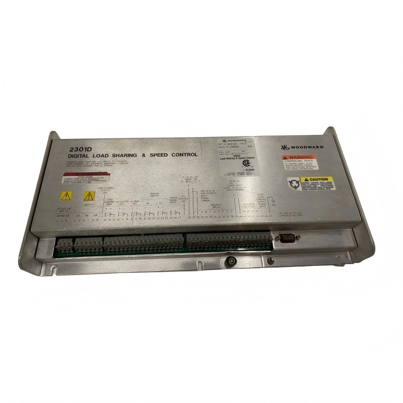
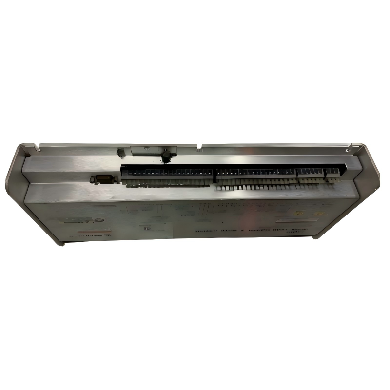
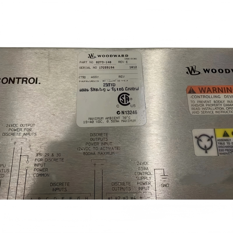
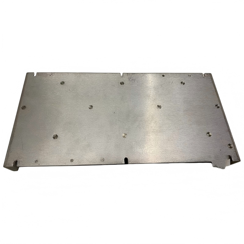
- Woodward
- 8273-140
- Full Authority Speed Control Unit
- USA
- 388 x 174.6 x 54 mm
- 1.95 kg
- Xiamen, China
- New & In Stock
- T/T, PayPal, Western Union
- 1 Year
- 1-3 Working Days
- DHL, UPS, TNT, FedEx and EMS.
- 24-Hour Service
- COO
- 73
Our advantage

Global Logistics
We have a 10-year logistics and express cooperation agreement, so our products can be shipped to any place in the world.

Brand new and original
Our products are imported in bulk from the place of origin. Because of the cooperative relationship, our products are all original and 100% new.

24-hour service
We provide 7*24 hours service to our customers. We will be there whenever you need us.

Price advantage
All our products are priced very favorably because we have our own warehouse and supply.
| Company Information | |||
| [email protected] | |||
| Mobile | +8615980777398 | ||
| +8615980777398 | |||
| 15980777398 |
Product Overview
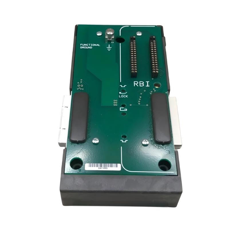
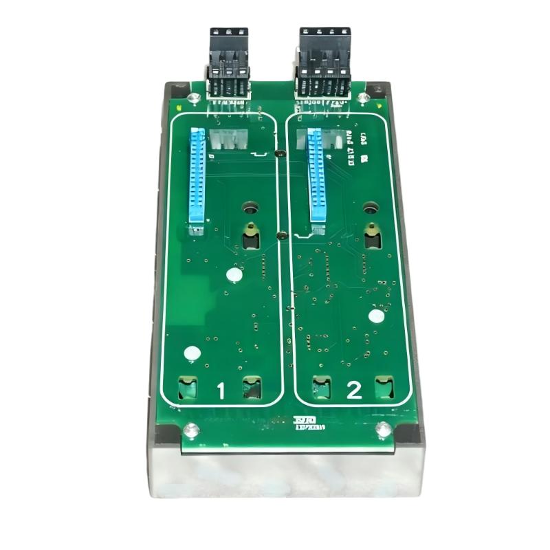
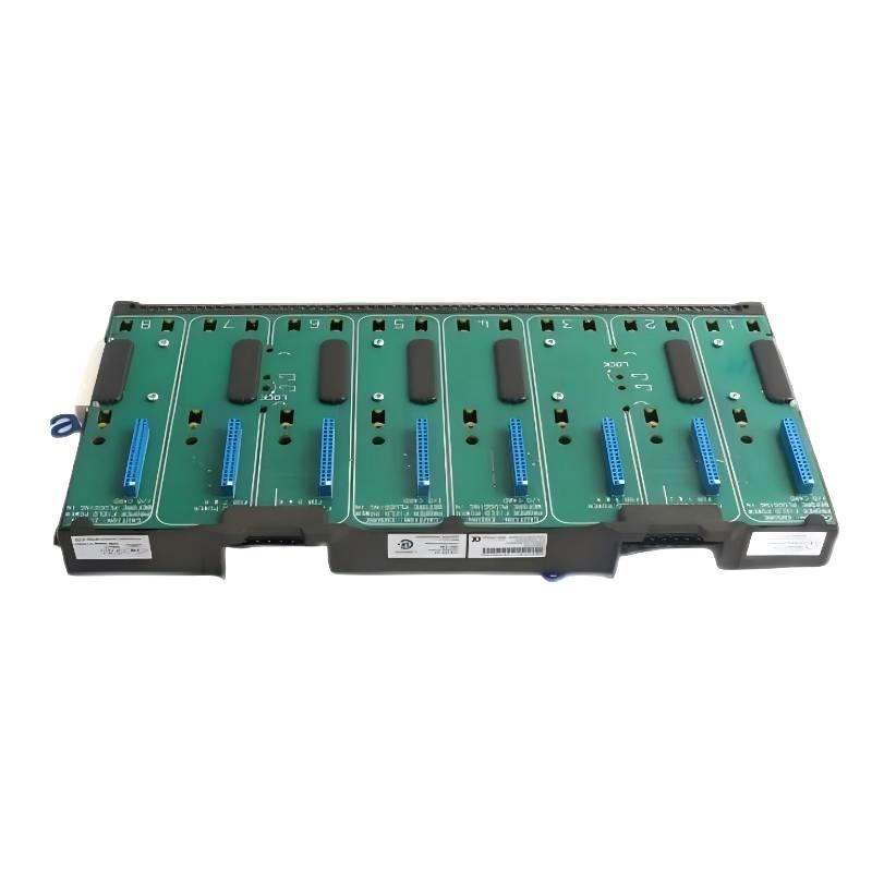
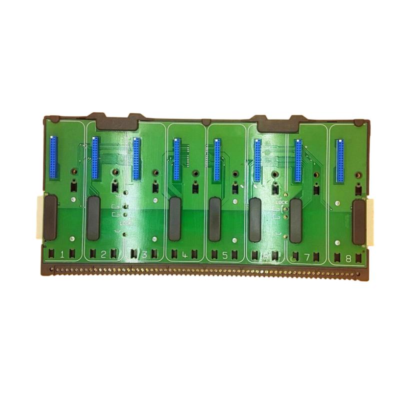
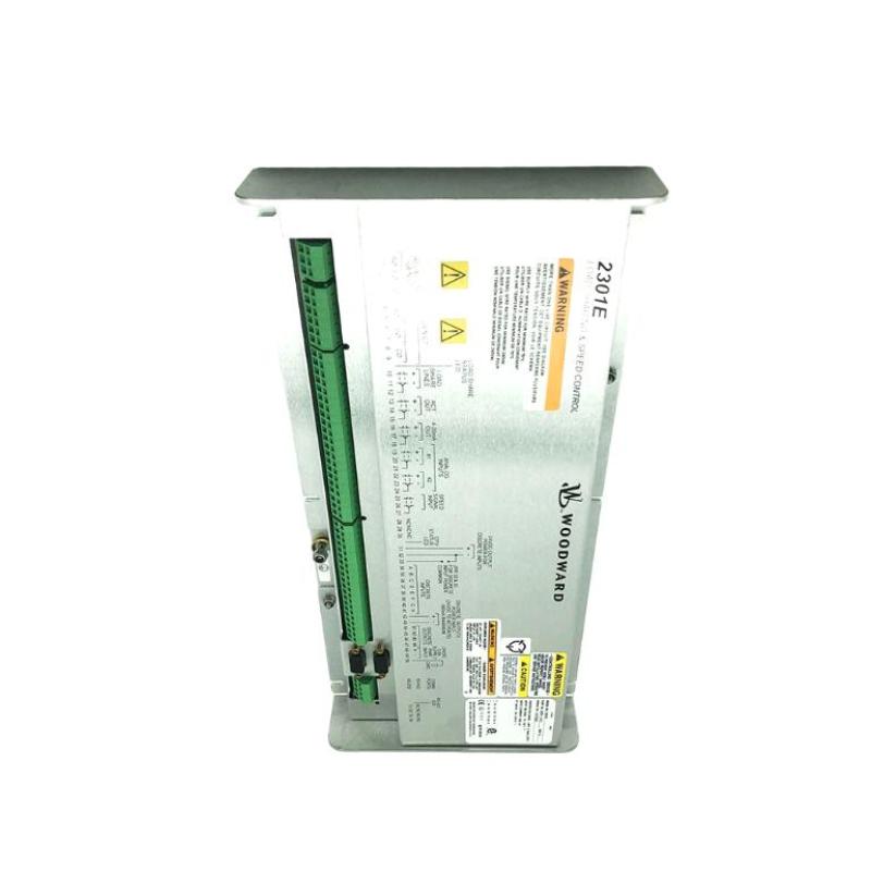
The Woodward 8273-140 Full Authority Speed Control Unit is a digital control component designed for applications in which the control system has primary authority over engine or turbine speed regulation. A full-authority speed-control arrangement can continuously process speed feedback and operating commands while controlling the associated actuator or fuel-governing system to maintain the required operating condition.
Compared with a simple speed-monitoring device, a full-authority controller participates directly in the control loop. It can respond to changes in engine speed, load, operating demand, and other configured inputs by modifying its control output.
The supplied physical specifications for the Woodward 8273-140 are 388 × 174.6 × 54 mm, with a stated weight of 1.95 kg.
Because a full-authority speed controller can directly influence rotating machinery, installation and commissioning should be carried out with appropriate equipment isolation, wiring verification, and controlled functional testing.
Technical Specifications
| Parameter | Details |
|---|---|
| Manufacturer | Woodward |
| Model | 8273-140 |
| Product Type | Full Authority Speed Control Unit |
| Main Function | Digital Engine / Turbine Speed Control |
| Control Architecture | Closed-Loop Speed Regulation |
| Primary Feedback | Rotational Speed |
| Control Output | Actuator / Governor Interface |
| Application | Engine, Turbine and Generator Systems |
| Installation | Industrial Control Cabinet / Panel |
| Dimensions | 388 × 174.6 × 54 mm |
| Weight | 1.95 kg |
Full-Authority Speed Control Function
The term Full Authority Speed Control indicates that the controller is responsible for making the primary speed-control decisions within the applicable control system.
A simplified control loop is:
Speed Reference
↓
8273-140 Speed Control Unit
↓
Actuator / Governor
↓
Fuel or Energy Input
↓
Engine / Turbine
↓
Shaft Speed
↓
Speed Feedback
↓
8273-140
The controller continuously evaluates the difference between desired and actual operating speed.
If the measured speed changes because of a load variation, the controller can modify its output to bring the machine back toward the required operating point.
Working Principle
The controller’s operation can be understood in several stages.
1. Speed Reference
The system establishes the required operating speed.
2. Speed Measurement
A suitable speed-sensing system provides feedback representing actual shaft speed.
3. Digital Processing
The controller processes the feedback and compares it with the required speed.
4. Control Calculation
The control logic determines the appropriate correction.
5. Actuator Command
The controller sends a command to the applicable actuator or governor.
6. Mechanical Response
The actuator modifies the engine or turbine’s energy input.
7. Feedback
The resulting speed is measured again, completing the closed-loop process.
This repeated feedback process allows the controller to respond to changing operating conditions.
Why Full Authority Control Matters
A full-authority controller can be responsible for a significant portion of the machine’s operating behavior.
Its control functions may influence:
- Speed stability
- Load response
- Acceleration
- Deceleration
- Operating setpoints
- Actuator positioning
- Generator frequency-related operation
- Engine or turbine response
The exact functions depend on the complete system configuration.
Role in Generator Applications
When an engine or turbine drives an electrical generator, speed regulation is particularly important.
A simplified relationship is:
Engine / Turbine Speed → Generator Rotation → Electrical Frequency
A properly functioning speed-control system helps the prime mover respond to load changes while maintaining the required operating speed.
For generator applications, abnormal speed-control behavior can therefore affect both mechanical operation and electrical-system performance.
Speed Feedback
Accurate feedback is fundamental to full-authority speed control.
A speed-feedback problem can appear as a controller fault even when the control unit itself is operating correctly.
Possible feedback problems include:
- Missing speed pulses
- Intermittent sensor signal
- Damaged sensor cable
- Loose terminals
- Electrical interference
- Incorrect sensor installation
- Incorrect signal configuration
Before replacing the controller, verify the complete speed-feedback path.
Control Output
The 8273-140 operates as part of a control chain between the digital control system and the machine’s actuator or governor.
A simplified output path is:
8273-140 → Actuator / Governor → Fuel or Energy Control → Engine / Turbine
The output must be appropriate for the associated actuator interface.
Incorrect output wiring or configuration can result in:
- Poor speed regulation
- Slow response
- Excessive speed variation
- Failure to reach the desired speed
- Unexpected actuator movement
Industrial Applications
The Woodward 8273-140 can be applied in industrial environments where full-authority speed regulation is required.
Potential applications include:
- Industrial engines
- Gas engines
- Diesel engines
- Turbine systems
- Generator sets
- Mechanical-drive systems
- Compressor drives
- Pump drives
- Power-generation equipment
- Rotating industrial machinery
The exact application depends on the equipment architecture and associated Woodward control components.
Installation Guide
Step 1 – Verify the Exact Model
Before installation, confirm:
- 8273-140
- Complete model identification
- Existing control-system configuration
- Speed-sensor arrangement
- Actuator interface
- Power requirements
- Terminal arrangement
- Existing mounting location
Do not assume that another 8273-series controller is interchangeable without verifying the complete system configuration.
Step 2 – Safely Isolate the Machine
Because the controller can directly influence machine speed, safe isolation is essential.
Before installation:
- Stop the engine or turbine.
- Isolate electrical power.
- Prevent automatic or remote startup.
- Isolate applicable fuel or energy sources.
- Follow lockout/tagout procedures.
- Verify the machine is in a safe maintenance state.
The objective is to prevent an unintended controller command from causing machine movement during installation.
Step 3 – Record the Existing Configuration
Before disconnecting the existing unit:
- Photograph the wiring.
- Label conductors.
- Record terminal numbers.
- Document speed-feedback connections.
- Record actuator connections.
- Document power connections.
- Record configuration settings.
- Note active alarms or diagnostic conditions.
This information provides an important reference during commissioning.
Step 4 – Remove the Existing Unit
Disconnect the wiring carefully.
Avoid:
- Pulling directly on cables
- Mixing terminal assignments
- Damaging connectors
- Leaving wires unidentified
- Applying excessive force to terminals
Place the removed controller in an ESD-safe location if it will be inspected later.
Step 5 – Inspect the Replacement
Inspect the 8273-140 for:
- Damaged terminals
- Bent contacts
- Cracked housing
- Corrosion
- Contamination
- Signs of overheating
- Mechanical damage
Check identification markings before installation.
Step 6 – Mount the Control Unit
The supplied dimensions are:
388 × 174.6 × 54 mm
The mounting structure should provide adequate mechanical support for the supplied 1.95 kg weight.
Allow sufficient clearance for:
- Wiring
- Ventilation
- Inspection
- Connector access
- Future maintenance
Wiring Considerations
A full-authority speed controller can involve several important electrical interfaces.
Power Connections
Verify that the control-unit power supply matches the actual equipment design.
Speed Feedback
The speed sensor must be correctly connected and routed to minimize interference.
Actuator Interface
The controller output must be connected to the appropriate actuator or governor circuit.
Auxiliary Inputs
Depending on the system, additional signals may include:
- Speed references
- Enable commands
- Start/stop signals
- Load signals
- Remote commands
- Alarm inputs
- Permissive signals
The exact wiring must follow the system’s electrical design.
Commissioning Procedure
Initial Inspection
Before applying power, verify:
- Correct model
- Correct mounting
- Correct wiring
- Secure terminals
- Correct speed-feedback connections
- Correct actuator connections
- No unintended shorts
Power-Up Verification
After the machine has been safely prepared:
- Apply control power.
- Observe controller status.
- Check diagnostic indications.
- Verify speed feedback.
- Confirm that the output remains in the expected safe condition.
Do not proceed with machine operation if unexpected output behavior is observed.
Speed Feedback Test
Verify that the controller receives a stable and believable speed signal.
Compare the controller indication with an independent speed measurement where appropriate.
A mismatch should be investigated before proceeding with full operational testing.
Controlled Start
During the initial startup:
- Start the prime mover under an approved procedure.
- Monitor speed continuously.
- Observe actuator response.
- Verify acceleration behavior.
- Check the speed setpoint.
- Monitor alarms and diagnostics.
Do not make unnecessary control-parameter changes during initial commissioning.
Load Response Test
Once stable operation has been established, verify the controller’s response to controlled load changes.
Observe:
- Speed deviation
- Recovery time
- Actuator response
- Steady-state stability
- Alarm behavior
The goal is to confirm that the closed-loop system responds predictably.
Common Failure Symptoms
| Symptom | Possible Cause |
|---|---|
| Controller does not power up | Supply or wiring problem |
| No speed feedback | Sensor or signal-path problem |
| Incorrect speed indication | Feedback or configuration issue |
| Engine speed oscillates | Feedback, tuning, actuator or load issue |
| Speed fails to reach setpoint | Output, actuator or fuel-system problem |
| Slow response | Actuator or control configuration issue |
| Unexpected output command | Configuration or input problem |
| Overspeed tendency | Feedback, actuator or control-system fault |
| Intermittent operation | Wiring, connector or power instability |
Troubleshooting Guide
Unit Does Not Power Up
Check:
- Control-power supply.
- Protective devices.
- Terminal connections.
- Grounding.
- Wiring continuity.
- Controller condition.
Verify the external power circuit before determining that the 8273-140 itself has failed.
No Speed Feedback
If the controller receives no valid speed information:
- Inspect the speed sensor.
- Check sensor wiring.
- Verify sensor mounting.
- Inspect connectors.
- Check signal quality.
- Verify input configuration.
- Compare the signal with an independent measurement.
A controller should not be condemned until the feedback path has been verified.
Incorrect Speed Reading
If the displayed speed does not correspond to actual machine speed:
- Check the sensor.
- Verify sensor installation.
- Inspect cable condition.
- Check shielding.
- Check signal quality.
- Verify configuration.
- Compare against an independent speed measurement.
An incorrect speed signal can cause the controller to make inappropriate corrections.
Speed Oscillation
Speed instability can result from several interacting causes:
- Noisy speed feedback
- Control-loop configuration
- Actuator dynamics
- Fuel-system response
- Mechanical load changes
- Mechanical problems
- Incorrect operating parameters
Start by verifying the feedback signal and actuator behavior before changing control settings.
Speed Does Not Reach the Setpoint
Possible causes include:
- Insufficient actuator movement
- Actuator limitation
- Fuel-system restriction
- Excessive load
- Incorrect speed reference
- Incorrect feedback
- Configuration problems
Follow the control loop from the controller output toward the actuator and prime mover.
Slow Speed Response
A slow response can be associated with:
- Actuator limitations
- Mechanical inertia
- Fuel-system response
- Control settings
- Incorrect feedback
- Excessive load changes
Compare actual actuator response with the controller’s commanded output to determine where the delay occurs.
Unexpected Speed Increase
An unexpected speed increase should be treated as a serious operating condition.
Possible causes include:
- Incorrect speed feedback
- Failed or abnormal actuator behavior
- Incorrect output wiring
- Control configuration error
- Fuel-control problems
- Governor problems
Return the machine to a safe condition using the approved operating or emergency procedure before continuing diagnostic work.
Preventive Maintenance
Recommended maintenance activities include:
- Controller visual inspection
- Terminal inspection
- Power-supply checks
- Speed-sensor inspection
- Wiring inspection
- Connector inspection
- Grounding verification
- Cabinet ventilation checks
- Alarm-history review
- Speed-trend analysis
- Actuator inspection
Preventive maintenance should focus on the entire control loop rather than only the electronic controller.
Speed Sensor Maintenance
The speed sensor is one of the most important external components in a closed-loop speed-control system.
Inspect for:
- Correct mounting
- Proper sensor position
- Damaged cables
- Loose connections
- Contamination
- Electrical interference
- Intermittent signals
- Degraded signal quality
A poor speed signal can cause instability even when the 8273-140 is operating normally.
Actuator and Governor Checks
When troubleshooting speed-control problems, inspect the actuator side as well.
Check:
- Mechanical movement
- Linkage condition
- Electrical connections
- Command response
- Feedback where applicable
- Mechanical binding
- Response time
A controller cannot compensate for an actuator that is mechanically stuck or electrically defective.
System Integration
The 8273-140 functions as one part of a complete speed-control architecture.
| Component | Function |
|---|---|
| Speed Sensor | Measures rotational speed |
| Speed Wiring | Transfers feedback |
| 8273-140 | Processes speed-control information |
| Actuator / Governor | Converts electrical command into mechanical action |
| Fuel / Energy System | Controls prime-mover energy |
| Engine / Turbine | Produces rotational power |
| Generator / Mechanical Load | Consumes the generated power |
| Protection System | Provides independent abnormal-condition response |
Effective troubleshooting requires understanding the interaction between all these components.
Replacement Considerations
Before replacing the Woodward 8273-140, record:
- Complete model number
- Existing wiring
- Speed-sensor type
- Power configuration
- Actuator interface
- Speed reference configuration
- Active alarms
- Existing operating symptoms
- Associated control equipment
After replacement, verify:
- Power-up behavior
- Speed feedback
- Control output
- Actuator response
- Speed stability
- Setpoint tracking
- Load response
- Alarm functions
Key Advantages
- Full-authority digital speed-control architecture
- Designed for rotating-machine applications
- Supports closed-loop speed regulation
- Interfaces speed feedback with actuator control
- Suitable for engine and turbine applications
- Useful for generator and mechanical-drive systems
- Supplied dimensions: 388 × 174.6 × 54 mm
- Supplied weight: 1.95 kg
- Suitable for industrial control environments requiring dedicated speed regulation
Technical FAQs
What is the Woodward 8273-140?
The Woodward 8273-140 is a Full Authority Speed Control Unit designed for applications requiring digital control of engine or turbine speed.
What does full authority mean?
It generally means that the controller has primary control responsibility for the applicable speed-regulation function, using feedback and control inputs to determine the required actuator command.
What is the basic control loop?
The basic loop is:
Speed Reference → Controller → Actuator → Engine/Turbine → Speed Feedback → Controller
Why is speed feedback important?
The controller needs accurate actual-speed information to determine whether the machine is operating above, below, or near the desired speed.
What are the dimensions?
The supplied dimensions are 388 × 174.6 × 54 mm.
What is the weight?
The supplied weight is 1.95 kg.
What can cause speed hunting?
Potential causes include unstable feedback, actuator problems, control configuration, fuel-system dynamics, mechanical load changes, or mechanical problems.
Should an unstable speed condition automatically lead to controller replacement?
No. The speed sensor, wiring, actuator, fuel system, mechanical load, and controller configuration should all be evaluated before replacing the control unit.
What should be verified after installing a replacement?
Power, speed feedback, output behavior, actuator response, setpoint tracking, speed stability, alarms, and controlled load response should all be checked.
Conclusion
The Woodward 8273-140 Full Authority Speed Control Unit is a dedicated digital control component for rotating machinery where accurate and responsive speed regulation is required. Its role within the closed-loop control system connects speed feedback, control logic, actuator commands, and the operating behavior of the engine or turbine.
Proper installation requires safe machine isolation, accurate wiring documentation, correct speed-sensor connections, secure mounting, and controlled commissioning. Troubleshooting should follow the complete control path rather than assuming that an abnormal speed condition is caused by the controller itself.
With supplied dimensions of 388 × 174.6 × 54 mm and a weight of 1.95 kg, the 8273-140 provides a substantial control-unit format for industrial engine, turbine, generator, and mechanical-drive applications.