Product Overview
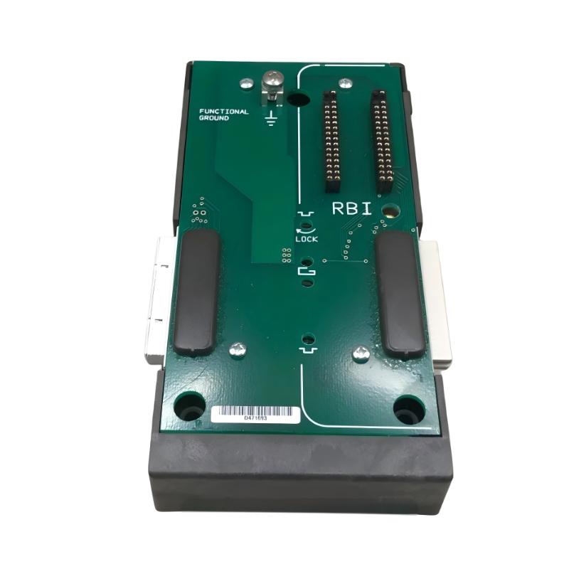
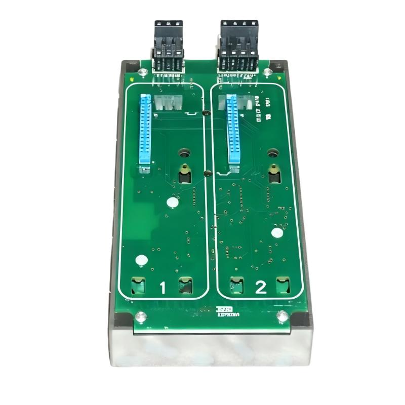
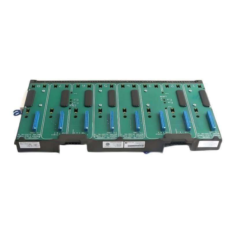
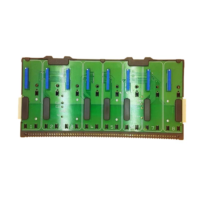
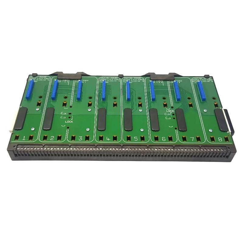
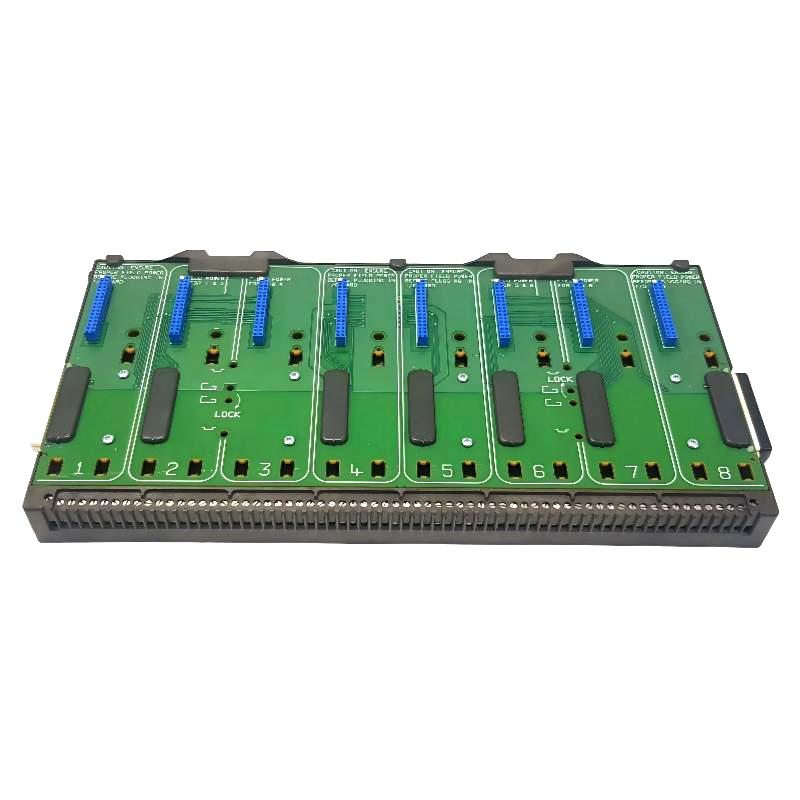
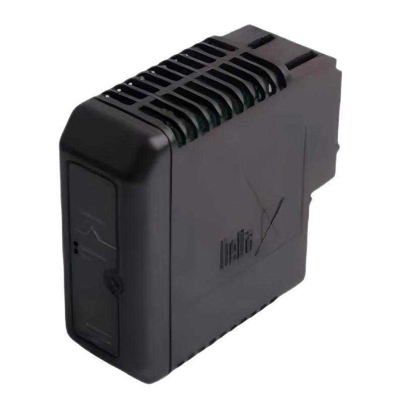
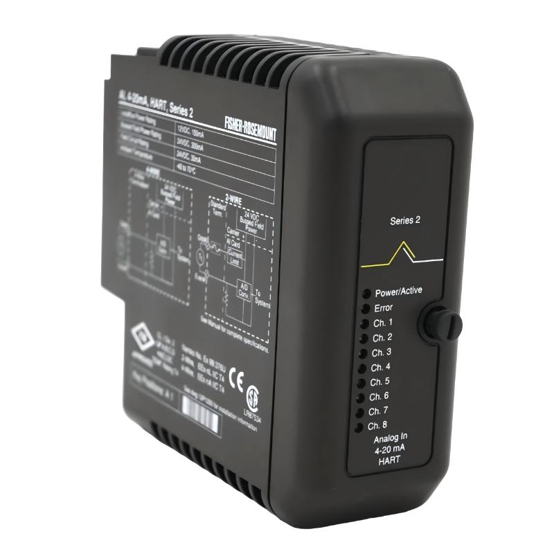
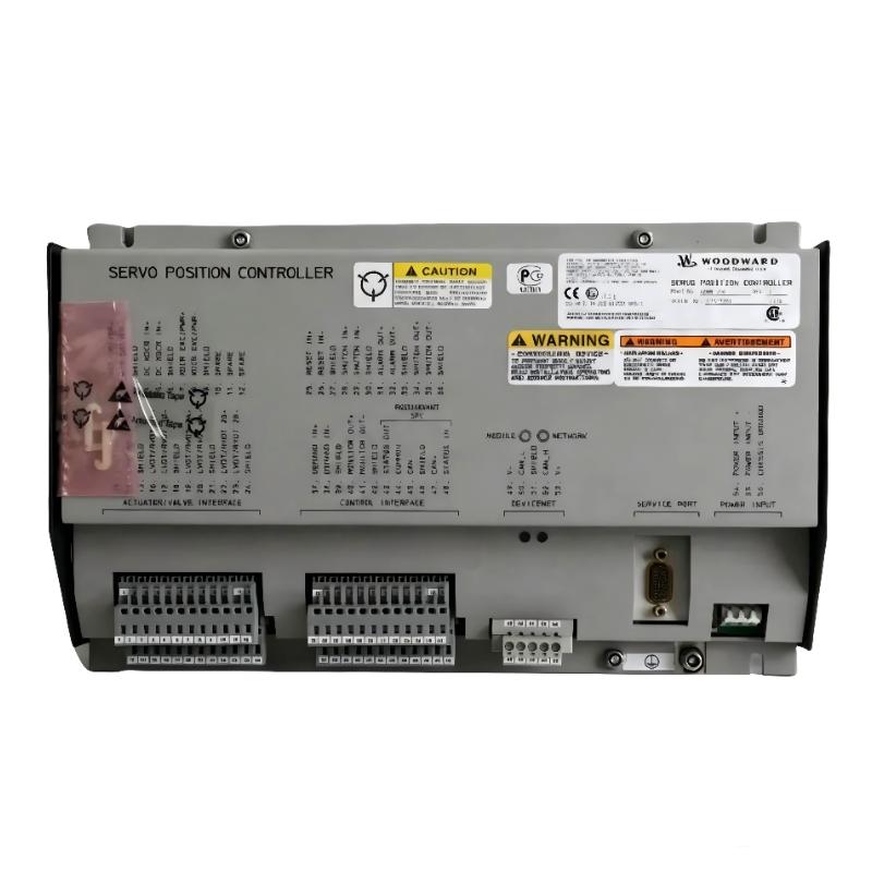
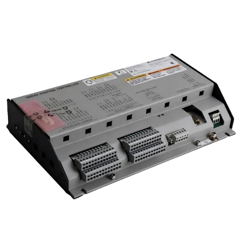
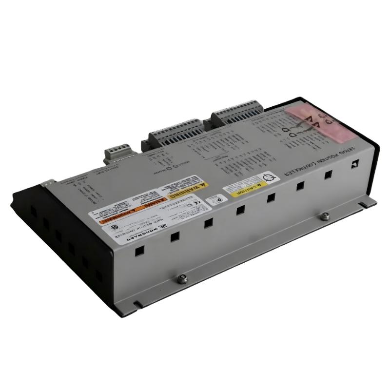
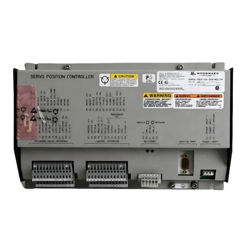
The Woodward 5441-669 Relay Interface Module is a compact industrial interface component designed to provide relay-based signal interfacing between control electronics and external equipment.
A relay interface module is commonly used where a controller needs to exchange discrete electrical signals with field devices while providing electrical isolation and practical switching capability. In an industrial control system, this type of module can help separate low-level control signals from external relay, contactor, alarm, or actuator circuits.
The supplied physical specifications for the Woodward 5441-669 are 120 × 20 × 70 mm, with a stated weight of 0.44 kg.
Because Woodward equipment is frequently integrated into engine, turbine, generator, and industrial control systems, correct terminal identification, relay configuration, supply voltage, and application-specific wiring should be verified before commissioning.
Technical Specifications
| Parameter |
Details |
| Manufacturer |
Woodward |
| Model |
5441-669 |
| Product Type |
Relay Interface Module |
| Main Function |
Relay Signal Interface |
| Signal Type |
Discrete / Relay |
| Application |
Industrial Control and Engine Management |
| Installation |
Control Cabinet / Interface Assembly |
| Function |
Signal Isolation and Relay Switching |
| Dimensions |
120 × 20 × 70 mm |
| Weight |
0.44 kg |
Function and Working Principle
The primary purpose of a relay interface module is to provide an electrical interface between a controller and external circuits.
A simplified signal path is:
Controller → Relay Interface → External Relay / Load / Field Circuit
or, for an incoming signal:
Field Contact → Relay Interface → Controller
The relay interface can provide switching and isolation between different sections of a control system.
A typical relay interface contains relay contacts that change state when the corresponding control circuit is energized.
The basic operating sequence is:
- The controller produces a discrete command.
- The interface receives the command.
- The relay coil or switching circuit responds.
- Relay contacts change state.
- The external circuit receives the required ON/OFF condition.
- The controller can monitor the resulting status where feedback is provided.
The actual contact arrangement and electrical ratings depend on the specific application and system design.
Role in Industrial Control Systems
Relay interfaces are particularly useful when a controller cannot directly drive an external circuit or when electrical isolation is required.
A simplified architecture is:
Control System
↓
5441-669 Relay Interface
↓
Relay Contacts
↓
External Equipment
Potential external circuits include:
- Alarm circuits
- Interlock circuits
- Contactors
- Solenoids
- Auxiliary relays
- Status indicators
- Shutdown circuits
- Equipment permissives
The interface therefore acts as a bridge between electronic control logic and conventional industrial electrical circuits.
Relay Interface Function
Signal Isolation
Relay-based interfaces can separate the control side from the switched-contact side.
This can reduce the direct electrical interaction between sensitive control electronics and external circuits.
Discrete Signal Switching
The module can be used within circuits where the required information is essentially:
- ON
- OFF
- Energized
- De-energized
- Open
- Closed
Equipment Interface
A relay interface can make it easier for a controller to communicate with equipment that uses conventional relay logic or contact circuits.
Industrial Applications
The Woodward 5441-669 may be used in industrial control environments where relay-based signal interfacing is required.
Typical application areas include:
- Engine control
- Turbine control
- Generator systems
- Power-generation equipment
- Industrial machinery
- Protection and shutdown systems
- Auxiliary equipment control
- Alarm systems
- Interlock systems
The exact application should always be determined from the equipment configuration in which the module is installed.
Installation Guide
Step 1 – Verify the Module
Before installation, confirm:
- Model: 5441-669
- Module identification
- Terminal arrangement
- Existing wiring
- Control-system compatibility
- Relay configuration
- Required electrical ratings
Do not install the module solely because the physical dimensions appear compatible.
Step 2 – Isolate Electrical Power
Before working on the relay interface:
- Shut down the associated equipment.
- Isolate control power.
- Isolate external load circuits where required.
- Apply lockout/tagout procedures.
- Verify absence of hazardous voltage.
- Follow the site’s electrical safety procedures.
Relay interface circuits can be connected to external power sources even when the controller itself is switched off.
Step 3 – Document Existing Wiring
Before removing an existing module:
- Photograph the wiring.
- Label each conductor.
- Record terminal numbers.
- Record relay contact assignments.
- Record supply connections.
- Document normally-open and normally-closed circuits.
- Note any external jumpers.
This is especially important because reversing relay contacts can produce unexpected equipment behavior.
Step 4 – Remove the Existing Module
Carefully disconnect:
- Control wiring
- Relay contact wiring
- Supply connections
- Signal wiring
Remove the module from its mounting location without stressing the connected conductors.
Step 5 – Inspect the Replacement
Inspect the Woodward 5441-669 for:
- Damaged terminals
- Cracked housing
- Bent contacts
- Corrosion
- Contamination
- Loose components
- Signs of overheating
Verify that terminal markings remain legible.
Step 6 – Install the Module
Mount the module securely in the appropriate control-panel location.
Reconnect the wiring according to the documented system configuration.
Pay particular attention to:
- Supply polarity where applicable
- Relay coil connections
- Common terminals
- Normally-open contacts
- Normally-closed contacts
- External load connections
Do not assume that a physically similar terminal is electrically equivalent.
Wiring Considerations
Relay interface wiring should be separated conceptually into two sides:
Control Side
This side receives the switching command from the controller or control circuit.
Contact / Load Side
This side interfaces with the external equipment.
A simplified arrangement is:
Controller Output → Relay Coil / Interface → Relay Contact → External Load
For monitoring:
External Contact → Relay Interface → Controller Input
The correct wiring depends on the required control logic and relay contact arrangement.
Commissioning Procedure
After installation, commissioning should be performed progressively.
Step 1 – Visual Inspection
Verify:
- Correct module
- Secure mounting
- Correct wiring
- No loose conductors
- No exposed unintended connections
Step 2 – Electrical Verification
Before energizing:
- Verify control voltage.
- Verify external circuit voltage.
- Check continuity where appropriate.
- Confirm contact states.
- Check for unintended shorts.
Step 3 – Functional Test
Apply the control command under controlled conditions.
Verify:
- Relay activation
- Correct contact transition
- Correct external-device response
- Correct feedback indication
Step 4 – System Test
Confirm that the complete control sequence operates correctly.
For safety-related circuits, testing should be performed according to the approved site commissioning procedure.
Common Failure Symptoms
| Symptom |
Possible Cause |
| Relay does not activate |
Missing control voltage or failed relay circuit |
| External device does not operate |
Contact-side wiring or load problem |
| Output remains permanently active |
Welded contact or incorrect wiring |
| Status is reversed |
NO/NC wiring error |
| Intermittent switching |
Loose terminal or worn relay contact |
| Relay chatters |
Unstable control voltage |
| Excessive heating |
Overloaded contact or incorrect circuit |
| Controller receives incorrect feedback |
Contact wiring or configuration problem |
Troubleshooting Guide
Relay Does Not Energize
Check:
- Control output from the controller.
- Control voltage at the module.
- Module wiring.
- Relay coil circuit.
- Terminal connections.
- Relay condition.
If the controller is not producing the expected command, troubleshoot the control system before replacing the relay interface.
Relay Energizes but Load Does Not Operate
If the relay activates but the external device does not respond:
- Check the relay contact circuit.
- Verify external supply voltage.
- Check fuse or circuit protection.
- Inspect load wiring.
- Verify NO/NC contact selection.
- Check the external actuator.
The relay interface may be functioning normally while the problem exists downstream.
Relay Contact Remains Closed
A continuously closed contact can result from:
- Incorrect wiring
- Wrong contact selection
- Welded relay contacts
- Control logic remaining active
- Incorrect system configuration
Disconnecting or modifying the circuit should only be performed under an approved maintenance procedure.
Relay Chatters
Relay chatter can be caused by:
- Unstable control voltage
- Poor terminal connections
- Intermittent controller output
- Electrical noise
- Inadequate supply conditions
- Mechanical relay wear
Measure the control-side voltage during switching rather than immediately replacing the module.
Intermittent Operation
Intermittent relay operation should prompt inspection of:
- Terminal tightness
- Connector condition
- Relay contacts
- Control wiring
- Load wiring
- Mechanical vibration
- Supply stability
Industrial vibration can gradually loosen poorly secured connections.
Relay Contact Inspection
Relay contacts are mechanical switching elements and can deteriorate over time.
Potential signs of contact problems include:
- Increased contact resistance
- Intermittent operation
- Failure to switch the load
- Contact welding
- Excessive heating
- Visible discoloration
When troubleshooting a high-cycle application, relay wear should be considered alongside electronic faults.
Preventive Maintenance
Recommended maintenance includes:
- Visual inspection
- Terminal inspection
- Wiring verification
- Relay operation testing
- Control-voltage verification
- Contact-condition inspection
- Cabinet cleaning
- Vibration inspection
- Thermal inspection
Maintenance records should include the module identification and any observed relay-contact abnormalities.
System Integration
The Woodward 5441-669 should be considered part of a larger control circuit.
| Component |
Typical Function |
| Controller |
Generates or receives control signals |
| Relay Interface |
Provides relay-based signal isolation and switching |
| Auxiliary Relay |
Extends switching capability |
| Contactor |
Controls higher-power loads |
| Solenoid |
Converts electrical command into mechanical action |
| Alarm Circuit |
Provides abnormal-condition indication |
| Interlock |
Prevents unsafe or undesired operation |
| Field Device |
Performs the controlled function |
A relay interface fault can therefore affect equipment that is physically located several wiring stages away from the module.
Replacement Considerations
Before replacing the 5441-669, record:
- Complete model number
- Module position
- Terminal assignments
- Control voltage
- External circuit voltage
- Relay contact configuration
- NO/NC wiring
- Associated controller
- External load
- Existing fault symptoms
After installation, compare the replacement module’s behavior with the documented original system condition.
Key Advantages
- Compact relay-interface design
- Suitable for discrete industrial control signals
- Provides a practical interface between electronic controllers and external relay circuits
- Supports equipment switching and status interfaces
- Useful in engine, turbine, generator, and industrial-control environments
- Compact 120 × 20 × 70 mm form factor
- Supplied weight of 0.44 kg
- Suitable for maintenance of compatible legacy Woodward control systems
Technical FAQs
What is the Woodward 5441-669?
The Woodward 5441-669 is a Relay Interface Module used for relay-based signal interfacing within compatible industrial control systems.
What is the purpose of a relay interface?
It provides a switching and interface path between control electronics and external electrical circuits, often allowing discrete signals to operate relays, alarms, interlocks, solenoids, or auxiliary equipment.
What are the dimensions of the 5441-669?
The supplied dimensions are 120 × 20 × 70 mm.
What is the weight?
The supplied weight is 0.44 kg.
Why is NO/NC wiring important?
Normally-open and normally-closed contacts produce different circuit states. Incorrect contact selection can cause equipment to operate in the opposite state from what the control logic expects.
What should be checked if the relay does not operate?
Check the controller command, control voltage, terminal wiring, relay circuit, and associated electrical connections before replacing the module.
What causes relay chatter?
Common causes include unstable control voltage, loose wiring, intermittent controller outputs, electrical noise, or relay wear.
Can a relay interface failure affect equipment downstream?
Yes. A relay interface may control or monitor external relays, solenoids, contactors, alarms, or interlocks. A failure can therefore affect equipment connected further downstream.
Conclusion
The Woodward 5441-669 Relay Interface Module provides a compact interface between industrial control electronics and external discrete electrical circuits. Its relay-based switching function makes it useful in applications involving equipment commands, status signals, alarms, interlocks, and auxiliary control circuits.
For reliable operation, installation should focus on correct terminal identification, control-voltage verification, NO/NC contact configuration, secure wiring, and proper electrical isolation. During troubleshooting, the controller, interface module, relay contacts, wiring, and downstream load should be examined as one complete signal path.
With supplied dimensions of 120 × 20 × 70 mm and a weight of 0.44 kg, the 5441-669 is a compact component suitable for space-constrained industrial control assemblies.