
NewsNEWCENTER
Featured products

Contact Us
Allen-Bradley 1746-OW8/A SLC 500 Relay Output Module Installation Guide
2026-08-04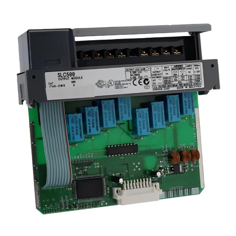
Table of Contents
- 1746-OW8/A Relay Output Module Overview
- Industrial Applications
- Installation Preparation
- Hardware Installation Procedure
- Relay Output Wiring Method
- PLC Configuration Setup
- Commissioning Process
- Installation Summary
1746-OW8/A Relay Output Module Overview
The Allen-Bradley 1746-OW8/A SLC 500 Relay Output Module Installation Guide provides a complete procedure for installing, wiring, configuring, and commissioning relay output modules in industrial automation control systems.
The 1746-OW8/A is an SLC 500 digital output module designed for controlling external electrical devices through relay contact switching. It provides reliable switching functions between the PLC control program and field equipment.
The module is commonly used for controlling motors, contactors, valves, alarms, and other industrial devices requiring relay-based output signals.
Industrial Applications
The Allen-Bradley 1746-OW8/A relay output module is widely used in industrial automation applications.
- Machine control systems
- Motor starter applications
- Solenoid valve control
- Industrial equipment control
- Packaging automation
- Process control systems
The relay output design provides flexibility for different field device control requirements.
Installation Preparation
Before installing the 1746-OW8/A module, engineers should complete the following preparation:
- Confirm SLC 500 chassis compatibility
- Check available module installation position
- Review electrical drawings
- Identify connected field devices
- Prepare suitable wiring cables
- Confirm grounding requirements
Proper preparation reduces wiring mistakes and improves commissioning efficiency.
Hardware Installation Procedure
The installation steps include:
- Disconnect PLC system power
- Select the correct chassis slot
- Insert the 1746-OW8/A module
- Ensure secure backplane connection
- Connect field output wiring
- Restore system power
A correct installation ensures stable communication between the SLC 500 processor and the relay output module.
Relay Output Wiring Method
Proper relay output wiring is essential for reliable industrial operation.
- Identify each output channel correctly
- Connect loads according to electrical drawings
- Check relay contact terminals
- Verify load voltage compatibility
- Tighten all terminal connections
- Install protection for inductive loads
1746_OW8A_INSTALL_CHECK

MODEL = 1746-OW8/A

CHECK_01 = MODULE_INSTALLATION
CHECK_02 = OUTPUT_WIRING
CHECK_03 = LOAD_CONNECTION
CHECK_04 = TERMINAL_TIGHTNESS
CHECK_05 = FUNCTION_TEST
PLC Configuration Setup
After completing hardware installation, engineers should verify the PLC configuration.
- Confirm output address assignment
- Check PLC ladder logic
- Verify output command sequence
- Test individual output channels
- Confirm field device response
Commissioning Process
The commissioning procedure includes:
- Check module installation status
- Apply PLC power
- Verify output indicators
- Test each relay output
- Confirm equipment operation
- Record commissioning information
Installation Summary
The Allen-Bradley 1746-OW8/A SLC 500 Relay Output Module installation process requires correct mounting, accurate wiring, PLC configuration, and complete testing. Proper installation ensures reliable output switching and stable operation in industrial automation systems.