
NewsNEWCENTER
Featured products

Contact Us
Allen-Bradley 1746-NT4/B SLC 500 Thermocouple/mV Analog Input Module Installation Guide
2026-07-29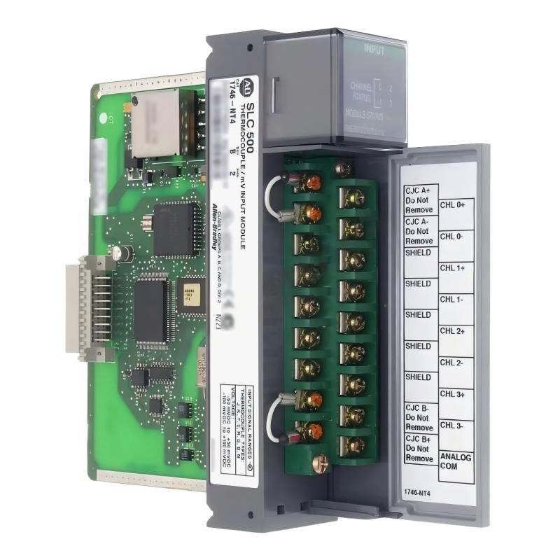
Table of Contents
- 1746-NT4/B Thermocouple/mV Analog Input Module Overview
- Key Features of 1746-NT4/B Module
- Industrial Applications of 1746-NT4/B
- Installation Preparation Requirements
- 1746-NT4/B Hardware Installation Procedure
- Thermocouple and mV Signal Wiring Method
- Channel Configuration and PLC Setup
- Startup and Commissioning Process
- Engineering Installation Best Practices
- Engineering Summary
1746-NT4/B Thermocouple/mV Analog Input Module Overview
The Allen-Bradley 1746-NT4/B SLC 500 Thermocouple/mV Analog Input Module Installation Guide provides a complete procedure for installing, wiring, configuring, and commissioning temperature measurement systems based on SLC 500 PLC platforms.
The 1746-NT4/B is a four-channel thermocouple and millivolt analog input module designed for industrial temperature acquisition applications. It receives signals from thermocouple sensors or millivolt devices, converts analog signals into digital values, and transfers measurement data to the SLC 500 processor for monitoring and control. :contentReference[oaicite:0]{index=0}
The module supports multiple thermocouple input types and low-level mV signal measurement, making it suitable for industrial processes requiring accurate temperature monitoring. :contentReference[oaicite:1]{index=1}
Key Features of 1746-NT4/B Module
The main functions of the Allen-Bradley 1746-NT4/B include:
- Four-channel temperature input capability
- Thermocouple signal measurement
- Millivolt analog input measurement
- Digital conversion for SLC 500 processor access
- Independent channel configuration
- Industrial temperature monitoring capability
These features allow engineers to integrate temperature sensors directly into automation control systems.
Industrial Applications of 1746-NT4/B
The Allen-Bradley 1746-NT4/B analog input module is commonly used in applications requiring reliable temperature data acquisition.
- Industrial furnace temperature monitoring
- Heating system control
- Plastic processing machinery
- Food production equipment
- Process manufacturing systems
- Energy management equipment
By collecting accurate temperature signals, the module helps PLC systems maintain stable process conditions and improve production efficiency.
Installation Preparation Requirements
Before installing the 1746-NT4/B module, engineers should complete the following preparation work:
- Confirm SLC 500 chassis compatibility
- Check available installation slot
- Identify thermocouple sensor types
- Prepare suitable extension cables
- Review electrical drawings
- Confirm grounding requirements
Proper preparation helps prevent incorrect wiring, unstable signals, and commissioning delays.
1746-NT4/B Hardware Installation Procedure
The 1746-NT4/B module is installed into an available SLC 500 chassis slot and communicates with the processor through the system backplane.
- Turn off the SLC 500 system power
- Select the correct chassis position
- Insert the 1746-NT4/B module carefully
- Confirm the module is securely connected
- Connect temperature sensor wiring
- Restore system power
A correct hardware installation ensures reliable communication between the analog input module and the PLC processor.
Thermocouple and mV Signal Wiring Method
Thermocouple and millivolt signals are low-level analog signals, therefore wiring quality has a direct impact on measurement accuracy.
Recommended wiring practices include:
- Connect each sensor to the correct input channel
- Verify thermocouple polarity
- Use proper sensor extension cables
- Avoid parallel routing with power cables
- Check terminal tightening condition
- Maintain proper shielding and grounding
1746_NT4B_INSTALL_CHECK

MODEL = 1746-NT4/B

CHECK_01 = MODULE_INSTALLATION
CHECK_02 = SENSOR_CONNECTION
CHECK_03 = THERMOCOUPLE_POLARITY
CHECK_04 = SIGNAL_SHIELDING
CHECK_05 = GROUNDING
During a temperature control system installation, engineers found unstable temperature readings after startup. After inspection, the thermocouple cable was installed near a motor power cable. Improving cable separation and shielding restored stable temperature measurement.
Channel Configuration and PLC Setup
After completing hardware wiring, each input channel must be configured according to the connected sensor type and measurement requirements.
- Select correct thermocouple input type
- Configure mV input mode when required
- Set channel operating parameters
- Verify PLC data mapping
- Check temperature value scaling
Correct configuration ensures that the PLC receives accurate temperature information from each connected sensor.
Startup and Commissioning Process
A complete commissioning procedure includes:
- Inspect module installation
- Check all sensor connections
- Apply system power
- Verify module status
- Monitor input channel values
- Compare readings with actual temperature
- Confirm process control operation
Each temperature input channel should be tested individually before the system enters production operation.
Engineering Installation Best Practices
Recommended installation methods include:
- Label every temperature input channel
- Keep analog wiring organized
- Separate signal cables from power cables
- Check sensor compatibility
- Maintain good grounding practices
- Record configuration parameters
Following professional installation practices improves temperature measurement reliability and reduces future maintenance problems.
Engineering Summary
The Allen-Bradley 1746-NT4/B SLC 500 Thermocouple/mV Analog Input Module Installation process requires careful attention to module mounting, sensor wiring, channel configuration, and commissioning verification. A correct installation method ensures accurate temperature measurement, stable analog signal acquisition, and reliable operation in industrial automation systems.