
NewsNEWCENTER
Featured products

Contact Us
Allen-Bradley 1746-HSTP1/E SLC 500 Stepper Controller Module Troubleshooting Guide
2026-07-24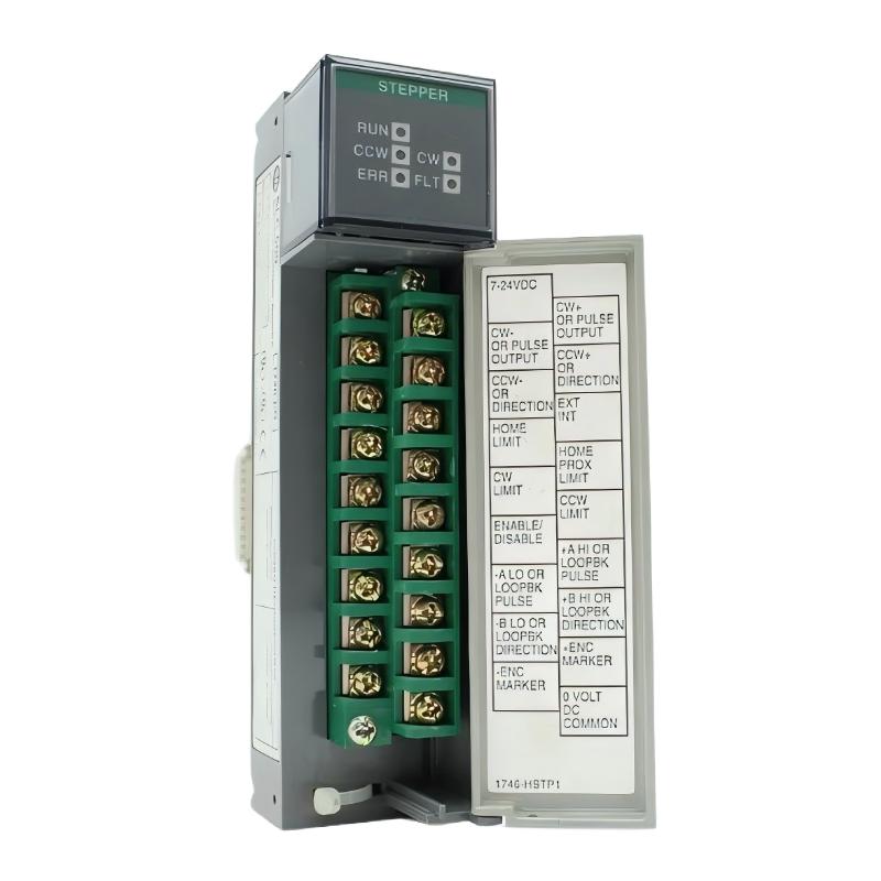
Table of Contents
- 1746-HSTP1/E Stepper Controller Module Troubleshooting Overview
- Field Case: 1746-HSTP1/E Motion Failure Analysis
- Common 1746-HSTP1/E Fault Symptoms
- Stepper Controller Fault Diagnosis Process
- Common Causes of Motion Control Failure
- Detailed Troubleshooting Procedure
- Fault Repair and Recovery Actions
- Post-Repair Testing and Verification
- Frequently Asked Questions
- Engineering Summary
1746-HSTP1/E Stepper Controller Module Troubleshooting Overview
The Allen-Bradley 1746-HSTP1/E SLC 500 Stepper Controller Module Troubleshooting Guide provides a professional maintenance method for diagnosing motion failures, positioning errors, communication problems, and wiring faults in industrial automation systems.
The 1746-HSTP1/E is a single-axis stepper motion control module used with SLC 500 PLC systems. When abnormal movement occurs, engineers need to analyze the complete motion control chain, including PLC commands, module status, pulse output signals, stepper drive operation, motor wiring, and mechanical load conditions.
A systematic Fault Diagnosis process can help identify the real cause quickly and avoid unnecessary module replacement.
Field Case: 1746-HSTP1/E Motion Failure Analysis
In one automated positioning system, the machine suddenly stopped completing the required positioning sequence. The PLC program was running normally, but the stepper motor failed to reach the commanded position.
Maintenance engineers checked the 1746-HSTP1/E module and found that the controller was still receiving commands correctly. Further inspection focused on the external motion control circuit.
The investigation found that the stepper drive input signal cable had become loose, causing unstable pulse transmission. After repairing the connection and testing the system again, the motor returned to normal positioning operation.
This case demonstrates that troubleshooting the 1746-HSTP1/E requires checking the entire motion system rather than assuming the controller module has failed.
Common 1746-HSTP1/E Fault Symptoms
Typical fault symptoms include:
- Stepper motor does not move
- Motor rotates in the wrong direction
- Positioning accuracy decreases
- Motion command cannot be completed
- Unexpected motor stopping
- Pulse output signal abnormal
- Communication problem with PLC system
These symptoms may be caused by incorrect parameters, wiring problems, drive faults, mechanical issues, or module communication errors.
Stepper Controller Fault Diagnosis Process
A professional Fault Diagnosis process should include:
- Check PLC motion command status
- Verify 1746-HSTP1/E module status
- Check pulse and direction signals
- Inspect stepper drive condition
- Verify motor wiring
- Check limit and home inputs
- Inspect mechanical movement
This method helps engineers identify whether the problem comes from the PLC program, controller module, drive system, motor, or mechanical equipment.
Common Causes of Motion Control Failure
The main causes of 1746-HSTP1/E failures include:
- Incorrect motion parameter settings
- Loose pulse signal wiring
- Wrong motor direction configuration
- Stepper drive malfunction
- Motor wiring errors
- Power supply instability
- Incorrect home or limit switch signals
- Mechanical load problems
In many industrial applications, motion problems are caused by external equipment conditions rather than the stepper controller module itself.
Detailed Troubleshooting Procedure
The recommended troubleshooting workflow includes:
- Record the current motion fault condition
- Check PLC output commands
- Verify module operating status
- Inspect pulse and direction wiring
- Check drive input signals
- Test motor operation manually
- Verify motion parameters
- Perform final movement testing
1746_HSTP1_DIAGNOSTIC

MODEL = 1746-HSTP1/E

STEP_01 = CHECK_PLC_COMMAND
STEP_02 = CHECK_MODULE_STATUS
STEP_03 = CHECK_STEP_SIGNAL
STEP_04 = CHECK_DIRECTION_SIGNAL
STEP_05 = CHECK_MOTOR_SYSTEM
Fault Repair and Recovery Actions
After identifying the fault source, engineers can apply the following corrective actions:
- Correct motion parameter settings
- Reconnect loose signal wiring
- Repair damaged cables
- Adjust motor direction settings
- Replace faulty stepper drive components
- Correct home and limit switch wiring
- Repair mechanical problems
Many 1746-HSTP1/E motion faults can be solved through proper diagnosis without replacing the controller module.
Post-Repair Testing and Verification
After completing troubleshooting, engineers should perform final verification:
- Confirm module communication
- Test pulse output operation
- Verify motor direction
- Check positioning accuracy
- Perform repeated movement tests
- Record maintenance results
Complete verification ensures that the stepper motion system returns to stable operation.
Frequently Asked Questions
Why does the 1746-HSTP1/E fail to control the stepper motor?
Possible causes include incorrect parameters, wiring problems, drive faults, power issues, or mechanical restrictions.
How can engineers confirm whether the module is damaged?
Engineers should first verify PLC commands, signal output, wiring, and external motion components before replacing the module.
What is the most common troubleshooting mistake?
Replacing the controller module without checking the stepper drive, signal wiring, and mechanical system can increase maintenance time and cost.
Engineering Summary
The Allen-Bradley 1746-HSTP1/E SLC 500 Stepper Controller Module Troubleshooting process requires systematic inspection of PLC commands, module status, pulse signals, drive operation, motor wiring, and mechanical conditions. Accurate Fault Diagnosis helps restore motion performance quickly, reduce unnecessary replacement costs, and improve the reliability of industrial automation equipment.