
NewsNEWCENTER
Featured products

Contact Us
Allen-Bradley 1734-OB2E Point I/O 2-Point Digital Output Module Installation Guide
2026-07-23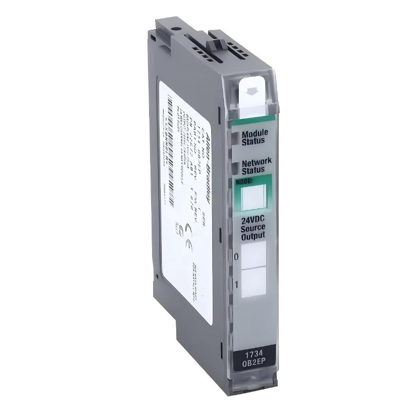
Table of Contents
- 1734-OB2E Point I/O 2-Point Digital Output Module Overview
- Industrial Applications of 1734-OB2E Output Module
- Installation Preparation Requirements
- 1734-OB2E Hardware Installation Steps
- Terminal Base and Output Wiring Connection
- Module Configuration and Parameter Setup
- Output Function Testing Procedure
- Startup Commissioning Process
- Engineering Installation Recommendations
- Engineering Summary
1734-OB2E Point I/O 2-Point Digital Output Module Overview
The Allen-Bradley 1734-OB2E Point I/O 2-Point Digital Output Module Installation Guide provides detailed instructions for hardware installation, electrical connection, configuration, and commissioning of the digital output module in industrial automation systems.
The 1734-OB2E is a POINT I/O digital output module designed for distributed control applications. It provides two output channels for controlling digital field devices and is commonly integrated into remote I/O stations through POINT I/O communication adapters.
Correct installation ensures reliable communication between the controller, POINT I/O system, and connected field devices.
Industrial Applications of 1734-OB2E Output Module
The Allen-Bradley 1734-OB2E is widely applied in automation environments requiring compact and flexible digital output control.
- Industrial machinery control
- Automated production lines
- Packaging equipment
- Assembly systems
- Material handling applications
- Remote actuator control systems
The compact POINT I/O design allows engineers to install output channels close to field equipment, reducing wiring complexity and improving system expansion capability.
Installation Preparation Requirements
Before installing the 1734-OB2E module, engineers should complete the following preparation work:
- Confirm POINT I/O system architecture
- Verify compatible terminal base installation
- Review electrical drawings
- Check field device specifications
- Prepare wiring tools and labels
- Confirm cabinet environmental conditions
Proper preparation reduces installation errors and improves commissioning efficiency.
1734-OB2E Hardware Installation Steps
The installation procedure should be performed carefully to ensure correct mechanical and electrical connection.
- Install the POINT I/O terminal base on the DIN rail
- Confirm terminal base locking position
- Connect required field wiring
- Insert the 1734-OB2E module into the base
- Secure the module locking mechanism
- Inspect the complete installation condition
A stable mechanical connection prevents intermittent communication and output operation problems during long-term use.
Terminal Base and Output Wiring Connection
Correct output wiring is essential for reliable operation of the 1734-OB2E module.
- Identify output channel terminals correctly
- Connect field loads according to electrical drawings
- Verify positive and negative power connections
- Check load device compatibility
- Tighten terminal connections properly
- Confirm cable routing condition
1734_OB2E_SETUP_CHECK

MODEL = 1734-OB2E

CHECK_01 = TERMINAL_BASE
CHECK_02 = OUTPUT_WIRING
CHECK_03 = FIELD_POWER
CHECK_04 = LOAD_CONNECTION
During a machine commissioning project, engineers completed the module installation but found that one output device remained inactive. Inspection revealed that the load cable was connected incorrectly. After correcting the wiring, the output function operated normally.
Module Configuration and Parameter Setup
After completing physical installation, the 1734-OB2E must be configured in the control system.
- Add the module to the controller project
- Configure the correct I/O structure
- Assign output tags
- Verify communication status
- Download the updated configuration
Correct configuration allows the controller to send accurate commands to each digital output channel.
Output Function Testing Procedure
Before production operation, engineers should perform output testing:
- Activate each output channel individually
- Confirm indicator status
- Check field device response
- Verify output switching performance
- Record test results
Individual channel testing helps identify wiring errors and configuration problems before system operation.
Startup Commissioning Process
A complete commissioning procedure includes:
- Inspect hardware installation
- Apply system power
- Check module status indicators
- Verify network communication
- Test output commands
- Confirm field equipment operation
- Complete commissioning records
Successful commissioning confirms that the 1734-OB2E module is correctly integrated into the automation system.
Engineering Installation Recommendations
Recommended practices for reliable installation include:
- Use clear wiring identification
- Keep control wiring organized
- Avoid unnecessary cable interference
- Check terminal tightening quality
- Maintain proper cabinet layout
- Document all installation changes
Following standardized installation methods can improve system stability and reduce future maintenance requirements.
Engineering Summary
The Allen-Bradley 1734-OB2E Point I/O 2-Point Digital Output Module Installation process requires careful attention to hardware mounting, terminal wiring, system configuration, and commissioning testing. A correct installation approach ensures stable digital output control, reliable field device operation, and long-term performance in industrial automation environments.