
NewsNEWCENTER
Featured products

Contact Us
Allen-Bradley 1440-TPS02-01RB Position Measurement Module Troubleshooting Guide
2026-07-09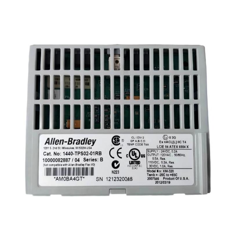
Table of Contents
- Field Case: Unstable Position Feedback in Rotating Equipment Monitoring
- 1440-TPS02-01RB Position Measurement Module Fault Symptoms
- XM-320 Position Measurement Module Fault Diagnosis Process
- Common Causes of 1440-TPS02-01RB Position Measurement Fault
- 1440-TPS02-01RB Troubleshooting Procedure
- Position Module Repair and Recovery Method
- System Verification After Troubleshooting
- FAQs on 1440-TPS02-01RB Troubleshooting
- Engineering Summary
Field Case: Unstable Position Feedback in Rotating Equipment Monitoring
The Allen-Bradley 1440-TPS02-01RB Position Measurement Module Troubleshooting process should begin with signal analysis instead of immediately replacing the module. In one industrial turbine monitoring application, operators noticed unstable axial position feedback during normal machine operation.
The PLC Controller displayed sudden position changes, while mechanical inspection confirmed that the shaft movement was normal. Engineers investigated the complete measurement path and found that the problem was related to signal transmission quality rather than a damaged Position Measurement Module.
This type of failure demonstrates why professional Fault Diagnosis requires checking sensors, wiring, communication, and System Configuration together.
1440-TPS02-01RB Position Measurement Module Fault Symptoms
Common symptoms found during field troubleshooting include:
- Position value jumping without actual mechanical movement
- Incorrect axial displacement indication
- Unstable position trend curves
- Unexpected alarm activation
- Intermittent channel signal loss
- Communication interruption between module and control system
These symptoms do not always indicate internal module failure. External signal conditions should be checked first.
XM-320 Position Measurement Module Fault Diagnosis Process
Experienced engineers normally follow a complete signal path investigation:
- Confirm the actual mechanical condition of the equipment
- Check position sensor installation and output stability
- Inspect field cable condition
- Verify terminal connection quality
- Check 1440-TPS02-01RB module status
- Review PLC Controller communication data
- Confirm System Configuration parameters
This method helps determine whether the problem originates from the Sensor, Module, wiring, or configuration settings.
Common Causes of 1440-TPS02-01RB Position Measurement Fault
The most common causes identified during industrial Troubleshooting include:
- Incorrect sensor calibration
- Improper sensor installation position
- Loose terminal connections
- Damaged or aged signal cables
- Electrical interference from nearby equipment
- Incorrect measurement scaling settings
- Communication instability
In practical maintenance situations, wiring and configuration problems are often more common than hardware damage inside the Position Measurement Module.
1440-TPS02-01RB Troubleshooting Procedure
A structured Fault Diagnosis workflow can be performed as follows:
- Review abnormal position trend history
- Compare faulty channel with normal channels
- Measure sensor output signal
- Check power supply stability
- Inspect wiring and shielding condition
- Verify communication status
- Confirm module configuration parameters
XM320_FAULT_DIAG

MODEL = 1440-TPS02-01RB
CHECK = SENSOR_SIGNAL
CHECK = CHANNEL_STATUS
CHECK = COMMUNICATION
CHECK = CONFIGURATION
During one field troubleshooting case, engineers found that a position signal fluctuated between 0.8 mm and 2.1 mm while the equipment remained stable. After checking the wiring path, a damaged shield connection was discovered. After repair, the position signal returned to a stable value near 0.9 mm.
Position Module Repair and Recovery Method
After identifying the root cause, engineers completed the following corrective actions:
- Repaired damaged signal cable shielding
- Re-tightened loose terminal connections
- Corrected sensor wiring arrangement
- Adjusted measurement calibration parameters
- Verified communication stability
The XM-320 monitoring system recovered normal operation without replacing the 1440-TPS02-01RB Position Measurement Module.
System Verification After Troubleshooting
- Confirm stable position readings during operation
- Verify alarm functions respond correctly
- Monitor long-term position trends
- Compare readings with mechanical reference values
- Record final troubleshooting results
A complete verification process ensures that the repaired system provides reliable measurement data under actual operating conditions.
FAQs on 1440-TPS02-01RB Troubleshooting
Why does the 1440-TPS02-01RB show incorrect position values?
Incorrect readings may be caused by sensor problems, wiring faults, grounding issues, communication instability, or incorrect configuration settings.
Can a wiring problem damage the Position Measurement Module?
In many cases, wiring problems mainly affect signal quality rather than directly damaging the module, but incorrect connections should always be corrected immediately.
What should be checked before replacing the module?
Engineers should check the sensor, cable condition, terminal connections, communication status, and System Configuration before replacing hardware.
Engineering Summary
The Allen-Bradley 1440-TPS02-01RB Position Measurement Module Troubleshooting process requires practical engineering analysis of the complete measurement chain. Field experience shows that unstable position signals are usually related to sensor installation, wiring quality, shielding, or configuration issues. A systematic Fault Diagnosis method can restore reliable operation while avoiding unnecessary hardware replacement.