
NewsNEWCENTER
Featured products

Contact Us
Allen-Bradley 1440-TB-C Screw Clamp Terminal Base Installation Guide
2026-07-06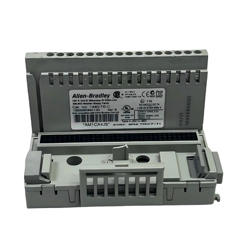
Table of Contents
- Installation Overview of 1440-TB-C Terminal Base
- XM System Wiring Layout Planning
- DIN Rail Mounting & Mechanical Locking
- Screw Clamp Wiring & Field Termination Rules
- Shielding & Grounding Strategy
- Installation Validation & Pre-Commission Check
- Common Installation Mistakes
- FAQs on 1440-TB-C Installation
- Engineering Summary
Installation Overview of 1440-TB-C Terminal Base
The Allen-Bradley 1440-TB-C screw clamp terminal base is designed for XM condition monitoring systems, providing secure electrical termination for vibration, speed, and dynamic measurement signals.
Proper installation directly affects signal stability, noise immunity, and long-term reliability of the monitoring system.
XM System Wiring Layout Planning
Before installation, engineers must define channel grouping and signal routing strategy:
- Separate vibration, speed, and dynamic input channels
- Keep analog signal wiring away from power cables
- Define grounding reference points early in cabinet design
- Maintain consistent labeling for each terminal group
DIN Rail Mounting & Mechanical Locking
- Align 1440-TB-C with standard DIN rail slot
- Press firmly until locking mechanism engages
- Verify no movement under vibration or cable tension
- Ensure uniform alignment across multiple terminal bases
Field experience shows that incomplete DIN rail engagement can cause intermittent signal instability during high vibration operation.
Screw Clamp Wiring & Field Termination Rules
- Use ferrules for all stranded conductors
- Tighten screw clamps to manufacturer torque specification
- Avoid over-tightening that damages conductor strands
- Ensure consistent wire stripping length for all terminals
TB_C_INSTALL /MODEL=1440-TB-C /TERMINATION_CHECK /TORQUE_VERIFY /WIRE_INTEGRITY
Shielding & Grounding Strategy
- Use single-point grounding for all signal shields
- Terminate shield at cabinet side only (typical practice)
- Avoid multiple grounding points to prevent loop currents
- Separate power ground and signal ground paths
Incorrect shielding is one of the most common causes of noise in XM condition monitoring installations.
Installation Validation & Pre-Commission Check
- Perform continuity test for all channels
- Verify torque on all screw clamps
- Check correct channel-to-sensor mapping
- Inspect shield termination integrity
- Confirm no loose wiring under mechanical stress
Common Installation Mistakes
- Skipping torque verification on screw clamps
- Using bare stranded wire without ferrules
- Incorrect shield grounding at multiple points
- Poor cable separation from VFD power lines
FAQs on 1440-TB-C Installation
Why is torque control important for installation?
Because screw clamp pressure directly affects electrical contact stability and signal quality.
Can wiring layout affect measurement accuracy?
Yes. Poor layout introduces EMI noise and signal distortion in XM systems.
Is shielding always required?
Yes, for low-level analog vibration and speed signals, shielding is essential.
Engineering Summary
The Allen-Bradley 1440-TB-C screw clamp terminal base requires precise installation practices including correct DIN rail mounting, torque-controlled termination, and disciplined grounding design. Field experience confirms that installation quality directly determines long-term XM system stability.