
NewsNEWCENTER
Featured products
Contact Us
Allen-Bradley 1440-TB-C Screw Clamp Terminal Base Fault Diagnosis Guide
2026-07-06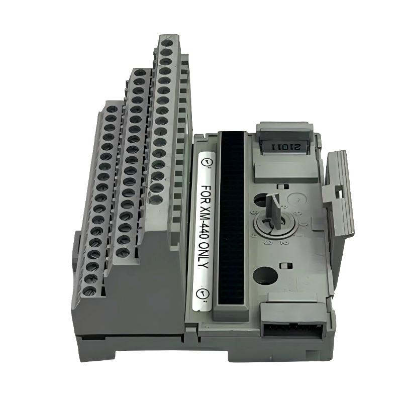
Table of Contents
- Field Case: Intermittent Vibration Channel Loss in XM System
- Fault Symptoms of 1440-TB-C Terminal Base
- Observed Signal Instability Behavior
- Root Cause Analysis (Mechanical Contact & EMI Coupling)
- Diagnostic Workflow for Terminal Base Issues
- Repair & Recovery Actions
- Prevention Strategy for Long-Term Stability
- FAQs on 1440-TB-C Faults
- Engineering Summary
Field Case: Intermittent Channel Drop in Compressor Monitoring System
The Allen-Bradley 1440-TB-C screw clamp terminal base is a passive but critical interface in XM condition monitoring systems. In one compressor station, engineers observed intermittent vibration signal loss on a single channel while other channels remained stable under identical operating conditions.
Fault Symptoms of 1440-TB-C Terminal Base
Typical field symptoms include:
- Random signal dropout on vibration or speed channels
- Unstable RMS values despite steady machine operation
- Noise spikes appearing without process change
- Signal recovery after cabinet vibration or cable movement
Observed Signal Instability Behavior
Field measurements showed inconsistent electrical behavior:
CHANNEL_1 = stable (2.2 mm/s RMS)
CHANNEL_2 = stable (2.0 mm/s RMS)
CHANNEL_3 = intermittent dropout / zero signal
NOISE_SPIKES = random high-frequency bursts
CONTINUITY_TEST = unstable at terminal group C
GROUND_REFERENCE = fluctuating potential difference
The instability pattern indicates termination and grounding issues rather than sensor or module failure.
Root Cause Analysis (Mechanical Contact & EMI Coupling)
The 1440-TB-C relies on screw clamp pressure and shield integrity for stable low-level signal transmission. Common failure mechanisms include:
- Loose screw clamp causing intermittent contact resistance
- Oxidation on conductor surfaces increasing impedance
- Improper shield termination introducing EMI noise
- Ground loop currents affecting reference stability
In one field case, a slightly loose shield drain wire caused intermittent noise spikes that were misinterpreted as mechanical vibration anomalies.
Diagnostic Workflow for Terminal Base Issues
A structured electrical and mechanical inspection is required:
- Perform continuity test while gently moving cable harness
- Verify screw clamp torque using calibrated torque driver
- Inspect shield termination integrity and grounding point
- Check for oxidation or discoloration on terminals
- Swap channels to isolate whether fault follows wiring
TB_C_DIAG /MODEL=1440-TB-C /CONTINUITY_SWEEP /SHIELD_TEST /GROUND_LOOP_ANALYSIS
Repair & Recovery Actions
- Re-torqued all screw clamp terminals to specification
- Re-terminated shield drain wires at single-point ground
- Replaced fatigued conductors with ferrule protection
- Reconfigured grounding to eliminate loop currents
After correction, signal stability returned and intermittent dropout events disappeared completely.
Prevention Strategy for Long-Term Stability
- Perform periodic torque inspection during maintenance cycles
- Use ferrules for all stranded conductors in vibration environments
- Maintain strict single-point grounding architecture
- Avoid routing signal cables near high-power switching equipment
- Inspect shielding integrity during shutdown maintenance
FAQs on 1440-TB-C Faults
Can a terminal base really cause signal loss?
Yes. Even small contact resistance variations can interrupt low-level analog signals in XM systems.
Why does signal recover when cables are moved?
Because movement temporarily restores unstable mechanical contact inside the clamp.
Is replacement always required?
No. Most issues are resolved through re-termination and torque correction rather than hardware replacement.
Engineering Summary
The Allen-Bradley 1440-TB-C screw clamp terminal base is a critical signal interface in XM condition monitoring systems. Field issues are most commonly caused by mechanical loosening, shielding defects, or grounding problems rather than module failure. Proper wiring discipline and torque control are essential for long-term measurement stability.