

ProductPRODUCT
Featured products
Contact Us
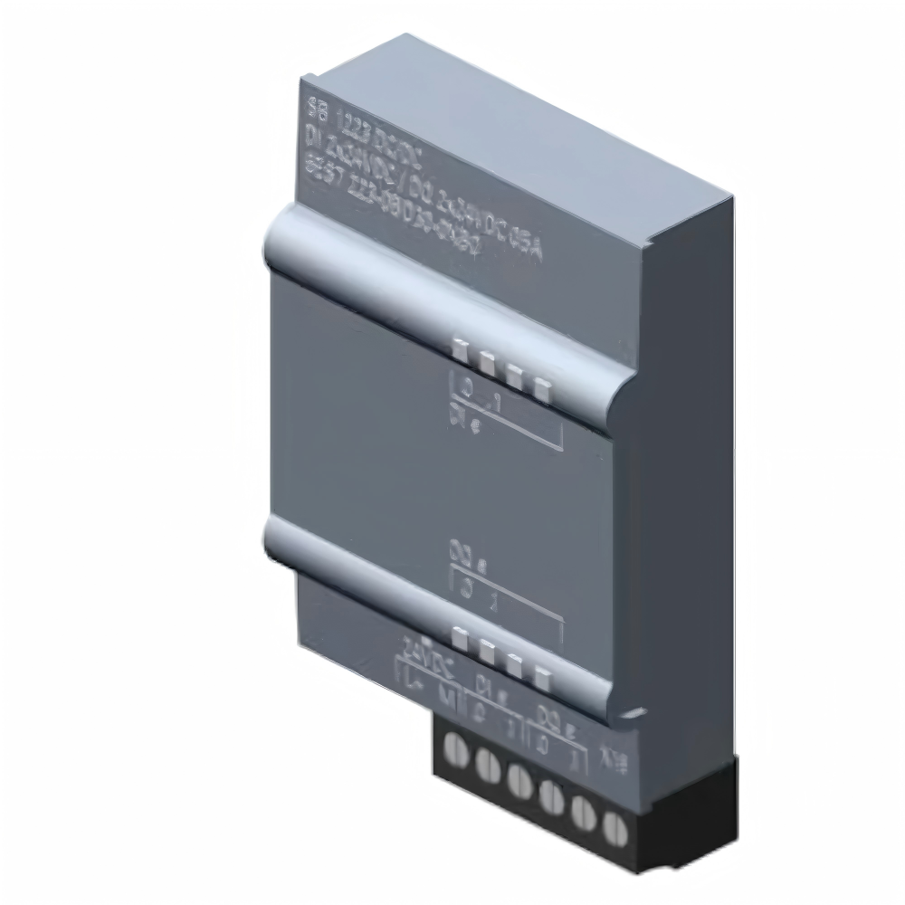
- Siemens
- 6AG1232-4HA30-4XB0
- SIMATIC S7-1200 SB 1232
- Germany
- 38 × 62 × 21 mm
- 0.03kg
- Xiamen, China
- New & In Stock
- T/T, PayPal, Western Union
- 1 Year
- 1-3 Working Days
- DHL, UPS, TNT, FedEx and EMS.
- 24-Hour Service
- COO
- 5
Our advantage

Global Logistics
We have a 10-year logistics and express cooperation agreement, so our products can be shipped to any place in the world.

Brand new and original
Our products are imported in bulk from the place of origin. Because of the cooperative relationship, our products are all original and 100% new.

24-hour service
We provide 7*24 hours service to our customers. We will be there whenever you need us.

Price advantage
All our products are priced very favorably because we have our own warehouse and supply.
| Company Information | |||
| [email protected] | |||
| Mobile | +8615980777398 | ||
| +8615980777398 | |||
| 15980777398 |
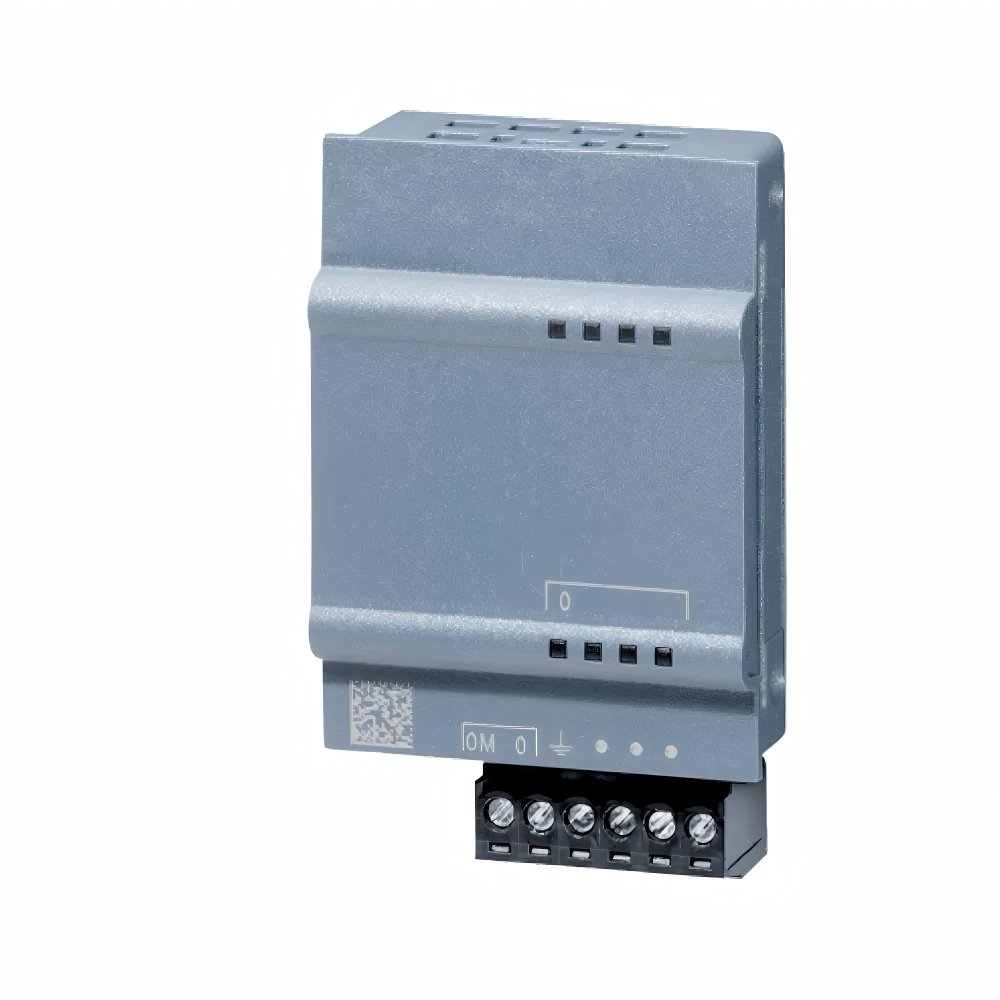
Siemens 6AG1232-4HA30-4XB0 — Product Description, Technical Specifications, Applications, Advantages, and Related Models
1. Product Overview
Model Number: 6AG1232-4HA30-4XB0
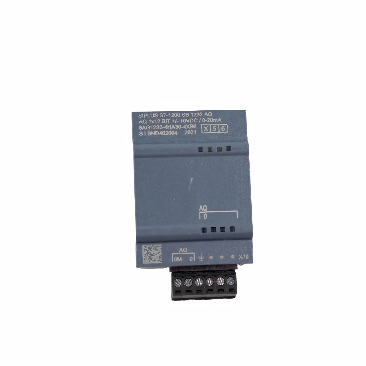
The 6AG1232-4HA30-4XB0 is a SIPLUS S7-1200 SB 1232 analog output signal board designed for industrial automation and machine-control applications. It provides one analog output channel that can generate either a voltage signal or a current signal, depending on the selected configuration.
The board is based on the standard 6ES7232-4HA30-0XB0 design and incorporates conformal coating to improve the protection of its electronic assemblies against specified environmental influences.
Its compact design allows it to be installed directly on a compatible SIMATIC S7-1200 CPU. This is useful when a machine requires an additional analog output but the control cabinet has limited space for conventional expansion modules.
The output signal can be used to control compatible equipment such as variable-speed drives, proportional control devices, signal converters, and other automation components that accept analog voltage or current references. The exact application depends on the electrical requirements of the connected device.
The product belongs to the SIPLUS S7-1200 family and the SB 1232 analog output signal-board series. Its main purpose is to convert a PLC command into an analog electrical signal that an external device can interpret.
2. Brand and Product Series
| Item | Description |
|---|---|
| Model Number | 6AG1232-4HA30-4XB0 |
| Brand | Siemens |
| Product family | SIPLUS S7-1200 |
| Product series | SIPLUS SB 1232 analog output signal boards |
| Module designation | SB 1232, AQ 1 × 12-bit |
| Product type | Analog output signal board |
| Base model | 6ES7232-4HA30-0XB0 |
| Number of analog inputs | 0 |
| Number of analog outputs | 1 |
| Voltage output range | -10 V to +10 V DC |
| Voltage output resolution | 12 bits |
| Current output range | 0–20 mA DC |
| Current output resolution | 11 bits |
| Rated supply system | Compatible S7-1200 CPU and signal-board installation |
| Additional protection | Conformal coating |
| Operating ambient temperature | -20 °C to +60 °C |
| Installation method | Direct installation on a compatible CPU |
| Main function | Analog command-signal generation |
3. Detailed Product Introduction
The 6AG1232-4HA30-4XB0 is intended for control systems that need to send an analog reference signal to an external device. In many industrial applications, the PLC does not simply switch equipment on or off. Instead, it needs to adjust a process continuously by varying a command value.
For example, a controller may need to adjust a drive’s speed reference, set a proportional valve command, or send a reference signal to a device that regulates a process variable. In these cases, an analog output can provide a signal that changes according to the PLC program.
This signal board offers two principal output modes:
- Voltage output: -10 V to +10 V DC, with 12-bit resolution.
- Current output: 0–20 mA DC, with 11-bit resolution.
The appropriate mode must be selected according to the requirements of the connected device. Voltage and current outputs are different electrical interfaces and should not be connected interchangeably without confirming the receiving device’s specifications.
The board is designed to be installed directly on a compatible S7-1200 CPU. Because it occupies the signal-board position rather than a conventional expansion-module position, it can be a useful solution for small machines and compact control cabinets.
The SIPLUS version incorporates conformal coating. This additional protection is intended to improve the suitability of the electronic assembly for specified industrial environmental conditions. It does not make the board waterproof, nor does it remove the need for proper enclosure design and compliance with the specified operating limits.
The board is best understood as a compact analog command interface. It provides the electrical output signal, while the PLC program determines what that signal represents and how it changes in response to the machine’s operating conditions.
4. Main Technical Parameters
| Parameter | Specification |
|---|---|
| Model Number | 6AG1232-4HA30-4XB0 |
| Brand | Siemens |
| Product family | SIPLUS S7-1200 |
| Product series | SB 1232 analog output signal board |
| Base model | 6ES7232-4HA30-0XB0 |
| Number of analog inputs | 0 |
| Number of analog outputs | 1 |
| Output signal type | Voltage or current |
| Voltage output range | -10 V to +10 V DC |
| Voltage output resolution | 12 bits |
| Current output range | 0–20 mA DC |
| Current output resolution | 11 bits |
| Minimum load impedance for voltage output | 1,000 Ω |
| Maximum load impedance for current output | 600 Ω |
| Typical backplane current consumption | 15 mA from 5 V DC |
| Maximum supply current for connected transmitter/reference supply | 25 mA, where applicable |
| Typical power loss | 1.5 W |
| Maximum shielded cable length | 10 m |
| Recommended signal cable | Shielded, twisted-pair cable |
| Output conversion principle | Differential |
| Maximum cycle time, voltage output | Approximately 300 μs with resistive load; up to 750 μs with 1 μF capacitive load |
| Current output response | Load-dependent; refer to the specified inductive-load conditions |
| Accuracy at 25 °C | Approximately ±0.5% of output range |
| Temperature error at 55 °C | Approximately ±1% of output range |
| Diagnostic functions | Supported |
| Output status indication | Supported |
| Degree of protection | IP20 as part of the installed system |
| Conformal coating | Yes |
| Conformal coating classification | Class 2 for high reliability |
| Operating ambient temperature | -20 °C to +60 °C |
| Width | 38 mm |
| Height | 62 mm |
| Depth | 21 mm |
| Net weight | 0.031 kg |
| Installation method | Directly on a compatible S7-1200 CPU |
| Main application | Analog control-signal output |
The electrical and mechanical values should be checked against the exact hardware revision before purchase or installation. In particular, the load impedance, output accuracy, and response time must be evaluated for the connected device and actual operating conditions.
5. Analog Output Characteristics
5.1 Voltage Output
The voltage output can be configured for a range of -10 V to +10 V DC, with a maximum resolution of 12 bits.
This type of signal is often used when a receiving device expects a voltage reference. Examples include compatible drive interfaces, signal-processing equipment, and industrial controllers.
The minimum specified load impedance for the voltage output is 1,000 Ω. The receiving device must therefore present a compatible input impedance, and the complete wiring arrangement must remain within the board’s electrical limits.
The PLC program determines the output command. For example, it may generate a low voltage for a low setpoint, a higher voltage for a higher setpoint, or a negative voltage where the application requires a bipolar command.
5.2 Current Output
The current output can be configured for 0–20 mA DC, with a maximum resolution of 11 bits.
Current signals are commonly used in industrial control systems because they can be suitable for transmitting analog commands through appropriately designed wiring and interfaces. A current reference may be used by a compatible actuator, controller, converter, or other receiving device.
The maximum specified load impedance for the current output is 600 Ω. The complete loop, including the receiving device and wiring, must be designed to stay within the permitted load.
A 0–20 mA output should not automatically be treated as a 4–20 mA output. If a receiving device requires 4–20 mA, confirm whether the intended signal can be generated by the available configuration or whether an additional signal conditioner or different module is required.
5.3 Resolution and Signal Quality
Resolution describes the number of discrete digital steps available to represent the output command. A 12-bit voltage output and an 11-bit current output have different numbers of representable levels.
Resolution is not the same as accuracy. Actual output performance also depends on the specified accuracy, load, wiring, temperature, electrical noise, and receiving equipment.
For applications that need precise control, the engineering design should account for both the digital resolution and the overall accuracy of the output path.
6. Power Supply and Electrical Requirements
The 6AG1232-4HA30-4XB0 is a signal board intended for a compatible S7-1200 CPU. It draws typical current from the 5 V DC backplane bus, with a specified typical consumption of 15 mA.
The technical documentation also lists a maximum 25 mA supply-current value associated with the transmitter/reference supply connection. The exact role of this supply connection should be checked in the wiring diagram for the applicable CPU and board configuration.
The typical power loss is 1.5 W. This figure should be considered when assessing thermal conditions inside the control cabinet.
The board should be installed according to the specified CPU compatibility, mounting, wiring, and environmental requirements. It is not intended to be treated as an independent analog controller with a universal external power interface.
Before commissioning, confirm that the configured output mode matches the receiving device. A mismatch between voltage and current modes can result in an incorrect control signal or an electrical connection that does not meet the intended interface requirements.
7. Product Applications
7.1 Variable-Speed Drive Reference Signals
Compatible drives may accept an analog voltage or current command to set a speed reference. The PLC can calculate the desired operating value and use the analog output board to generate the corresponding reference signal.
For example, a control program may adjust a drive’s speed according to a process setpoint, operator command, or feedback value. The board supplies the analog signal, while the drive performs its own internal control and power conversion.
The required signal range must be confirmed from the drive’s interface specification before wiring.
7.2 Proportional Valve Control
Some proportional valves and associated control devices accept analog command signals. The signal can represent a requested valve position, flow setting, or other control reference, depending on the receiving device.
The board can provide the command signal when the valve controller supports the configured voltage or current range. The valve’s power supply, control electronics, and feedback arrangements must be designed separately.
7.3 Industrial Process Regulation
Industrial processes often require the controller to adjust an operating value continuously rather than simply switching a device on or off.
An analog output may be used to send a setpoint to a compatible external regulator or actuator. The PLC program can modify the output in response to operator input, a control algorithm, process feedback, or a programmed sequence.
7.4 Heating and Cooling Equipment
Heating and cooling systems may use analog references to control compatible power controllers, regulators, or other equipment.
The signal board can provide a voltage or current command when the receiving device supports the corresponding interface. The board does not itself supply the heating or cooling power; it provides the control signal used by the external equipment.
7.5 Pressure, Flow, and Level Control
A process-control system may need to adjust a pump, valve, drive, or external regulator according to pressure, flow, or level measurements.
The PLC can calculate a suitable command and output it through the signal board. The relevant sensors and analog input channels acquire process measurements, while the analog output sends the resulting control reference to a compatible device.
7.6 Machine Automation
Small and medium-sized machines may need one analog output for speed adjustment, positioning references, process setpoints, or external equipment control.
The board is useful when the machine already uses a compatible S7-1200 CPU and only one additional analog output is needed. Its compact format helps avoid the need for a separate conventional signal module in applications where the signal-board arrangement is appropriate.
7.7 Packaging and Material Handling
Packaging machines and material-handling equipment sometimes use analog references for speed control, tension adjustment, or process regulation.
The board can provide the required analog command to compatible equipment, allowing the PLC to adjust the command as the machine changes operating state.
The actual control performance depends on the receiving equipment, mechanical system, PLC program, and any feedback devices.
7.8 Laboratory and Test Equipment
Some industrial test systems require an analog reference signal to operate a compatible external device or test interface.
The board can be used where its output ranges, resolution, accuracy, and electrical limitations meet the test system’s requirements. Applications requiring very high precision should assess the complete signal chain rather than relying on output resolution alone.
8. Main Product Advantages
8.1 Adds an Analog Output Without a Separate Standard Module
The board is designed to install directly on a compatible S7-1200 CPU. This makes it useful when a control system requires a single analog output but has limited cabinet space.
It can be an efficient choice for compact machines that need a simple analog command interface alongside their existing PLC functionality.
8.2 Supports Both Voltage and Current Output Modes
The board can generate either a -10 V to +10 V voltage signal or a 0–20 mA current signal, according to the selected configuration.
This provides flexibility when integrating equipment that uses different analog command interfaces. The correct mode must be chosen before commissioning, based on the receiving device’s electrical specification.
8.3 Compact Physical Size
The board measures approximately 38 × 62 × 21 mm and weighs about 0.031 kg.
Its small size makes it suitable for installations where space is limited and the system can use a signal board directly on the CPU. Cabinet design must still account for wiring access, ventilation, and the specified mounting requirements.
8.4 Conformal-Coated Electronics
The SIPLUS version incorporates conformal coating intended to improve protection against specified environmental influences.
This can be useful in industrial installations where electronic assemblies need additional protection compared with standard uncoated products. It does not eliminate the need for suitable enclosures or make the board immune to every chemical, liquid, or environmental condition.
8.5 Integration with an Existing PLC Program
The output can be controlled by the S7-1200 program, allowing analog commands to be generated as part of the machine’s normal operating sequence.
This can help integrate speed references, proportional commands, and process setpoints into an existing control architecture.
8.6 Diagnostic Functions
The board supports diagnostic functions and output-status indication. These capabilities can assist with commissioning and troubleshooting when used with a properly configured PLC system.
The actual diagnostic information available depends on the module, CPU, engineering configuration, and system implementation.
8.7 Suitable for Different Control Tasks
A single analog output can serve a range of tasks, including sending a setpoint to a compatible drive, controller, or actuator.
This makes the board useful for relatively simple applications that do not require several independently controlled analog outputs.
8.8 Defined Electrical Limits
The specified voltage-output load impedance and current-output load impedance provide clear design limits for the receiving circuit.
Checking these values before installation helps avoid an incompatible load and supports more reliable operation.
9. Installation and Configuration Recommendations
Before installing the 6AG1232-4HA30-4XB0, verify that the target CPU supports the signal board and that the selected hardware configuration is compatible with the engineering software and firmware in use.
Confirm the required analog interface of the receiving device. Check whether it expects a voltage or current signal, the required range, the permitted load, and the intended reference or common connection.
Configure the output mode and the PLC program consistently with the physical wiring. Do not assume that every device accepting a current signal supports both 0–20 mA and 4–20 mA.
Use suitable signal wiring and follow the installation instructions for shielding, grounding, and routing. Keep analog signal conductors appropriately separated from high-current or high-interference wiring where practicable.
Check the output value during commissioning using an appropriate measuring instrument and a suitable load. Verify the output at representative command values and confirm that the receiving device responds as expected.
Finally, install the board within the specified environmental limits and ensure that the control cabinet provides suitable protection. Conformal coating is an additional protective feature, not a substitute for correct installation.
10. Five Related Models
The models below are related to the S7-1200 analog output family or provide complementary analog signal functions. They differ in environmental specifications, output-channel count, or whether they handle analog input rather than output signals.
| Model Number | Product Description | Main Parameters | Dimensions (W × H × D) | Weight (kg) | Typical Application |
|---|---|---|---|---|---|
| 6AG1232-4HA30-5XB0 | SIPLUS SB 1232 analog output signal board, extended-temperature variant | 1 analog output; ±10 V at 12 bits or 0–20 mA at 11 bits; -40 °C to +60 °C; startup at -25 °C | Approx. 38 × 62 × 21 mm | 0.031 | Compact S7-1200 systems requiring a wider lower-temperature operating range |
| 6ES7232-4HA30-0XB0 | Standard SB 1232 analog output signal board | 1 analog output; ±10 V at 12 bits or 0–20 mA at 11 bits; standard environmental design | Approx. 38 × 62 × 21 mm | Approx. 0.031 | Standard industrial analog command output |
| 6ES7232-4HD32-0XB0 | SM 1232 analog output module | Multiple analog output channels; supports configured voltage/current ranges according to module specification | Approx. 45 × 100 × 75 mm; verify exact revision | Verify exact revision | Applications requiring more analog outputs |
| 6ES7231-4HF32-0XB0 | SM 1231 analog input module | General analog input for compatible voltage/current signals; input ranges and channel configuration depend on the exact model | Approx. 45 × 100 × 75 mm; verify exact revision | Verify exact revision | Acquiring pressure, flow, level, and other analog sensor signals |
| 6ES7234-4HE32-0XB0 | SM 1234 combined analog input/output module | Combined analog inputs and outputs; exact channel count and ranges depend on the model specification | Approx. 45 × 100 × 75 mm; verify exact revision | Verify exact revision | Applications requiring both analog measurement and analog control |
Selection note: The standard and SIPLUS versions should not be treated as identical in environmental performance. Confirm the operating-temperature range, startup requirements, electrical ratings, CPU compatibility, and current mechanical specifications before selecting a replacement.
11. Five Popular Models from the Same Brand
These products are commonly used in S7-1200 automation systems. They provide CPU processing, digital input/output, or general analog measurement and can complement an analog output signal board in a larger control design.
| Model Number | Product Description | Main Parameters | Dimensions (W × H × D) | Weight (kg) | Typical Application |
|---|---|---|---|---|---|
| 6ES7214-1AG40-0XB0 | SIMATIC S7-1200 CPU 1214C | PLC CPU; integrated digital I/O; Ethernet communication; supports compatible expansion modules | Approx. 110 × 100 × 75 mm | Approx. 0.445 | General machine control and automation |
| 6ES7215-1AG40-0XB0 | SIMATIC S7-1200 CPU 1215C | PLC CPU; integrated I/O and communication functions; compatible expansion support | Approx. 130 × 100 × 75 mm | Approx. 0.475 | More demanding machine-control applications |
| 6ES7221-1BH32-0XB0 | SM 1221 digital input module | Digital input expansion; discrete field-signal acquisition; confirm channel count and input ratings | Approx. 45 × 100 × 75 mm | Approx. 0.150 | Pushbuttons, limit switches, and status signals |
| 6ES7222-1BH32-0XB0 | SM 1222 digital output module | Digital output expansion; controls compatible discrete loads within the specified ratings | Approx. 45 × 100 × 75 mm | Approx. 0.150 | Relays, indicator lamps, and discrete control signals |
| 6ES7231-4HF32-0XB0 | SM 1231 general analog input module | Analog input for compatible voltage/current signals; verify exact input ranges and channel configuration | Approx. 45 × 100 × 75 mm | Approx. 0.180 | Pressure, flow, level, and other analog-transmitter signals |
The dimensions and weights for the related and popular products are indicative reference values unless specifically confirmed for the exact ordering number. Verify the current technical drawing and product documentation before using them for cabinet design, replacement planning, or procurement.
12. How to Select the Right Analog Output Product
Choose 6AG1232-4HA30-4XB0 when:
- One analog output channel is sufficient.
- The system uses a compatible S7-1200 CPU.
- A voltage reference of -10 V to +10 V or a current reference of 0–20 mA meets the receiving device’s requirements.
- A compact, directly mounted signal board is preferred.
- Conformal-coated electronics are desirable for the specified environmental conditions.
- The operating ambient temperature is within -20 °C to +60 °C and the startup requirement is acceptable.
Choose 6AG1232-4HA30-5XB0 when:
- The same general analog output functionality is required.
- The installation needs the wider lower-temperature operating range of the -5XB0 variant.
- The specified startup conditions and operating limits match the actual installation environment.
Choose the standard 6ES7232-4HA30-0XB0 when:
- The standard environmental design is suitable.
- The project does not require the additional environmental protection features of the SIPLUS version.
- The output range and single-channel arrangement meet the application requirements.
Choose a multi-channel analog output module when:
- Several independent devices need analog command signals.
- The machine requires more than one analog output.
- The available CPU signal-board position is insufficient for the intended design.
Choose a general analog input module when:
- The main requirement is to measure a voltage or current signal from a field sensor.
- The system needs to acquire pressure, flow, level, or other process variables.
- The selected input module supports the signal range and electrical interface of the sensor.
Choose a combined analog input/output module when:
- The application needs both sensor measurements and analog control commands.
- The channel count and electrical ranges match the system requirements.
- A combined module is more suitable than separate input and output hardware.
13. Important Engineering Considerations
An analog output board is only one part of the complete control loop. The PLC program generates the command, the signal board converts it into an electrical output, and the receiving device interprets that output and performs the required action.
For reliable operation, the entire signal path should be checked. This includes the PLC configuration, selected output mode, signal wiring, load impedance, receiving-device input range, and any scaling applied in the PLC program.
Where the analog command controls a drive or actuator, the control system should also define appropriate behavior for startup, shutdown, communication faults, and abnormal operating conditions. The signal board itself does not replace the protective functions required by the machine or process.
If the application requires a 4–20 mA interface, high accuracy, a larger number of output channels, or a different operating-temperature range, those requirements should be evaluated before the model is finalized.
14. Summary
The 6AG1232-4HA30-4XB0 is a compact SIPLUS S7-1200 SB 1232 analog output signal board intended for industrial control applications that require one analog command channel.
It supports a voltage output of -10 V to +10 V DC with 12-bit resolution or a current output of 0–20 mA DC with 11-bit resolution. It is designed for direct installation on a compatible S7-1200 CPU and incorporates conformal coating for specified environmental conditions.
With dimensions of approximately 38 × 62 × 21 mm and a net weight of 0.031 kg, the board is well suited to compact control designs where a single analog output is needed.
Its most important selection criteria are CPU compatibility, output type, signal range, load impedance, required accuracy, environmental conditions, and the needs of the connected equipment. Checking these factors before installation helps ensure that the board is suitable for the intended machine or process.