

ProductPRODUCT
Featured products
Contact Us
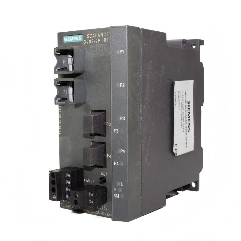
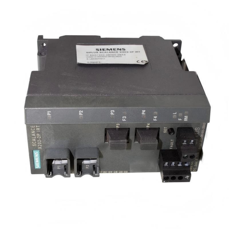
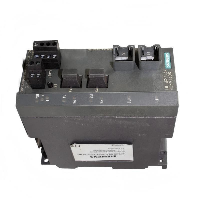
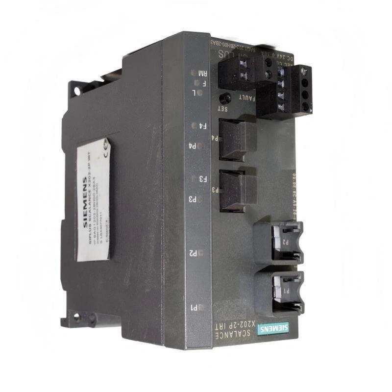
- Siemens
- 6AG1202-2BH00-2BA3
- Digital Output Module
- Germany
- 60 × 125 × 124 mm
- 0.78 kg
- Xiamen, China
- New & In Stock
- T/T, PayPal, Western Union
- 1 Year
- 1-3 Working Days
- DHL, UPS, TNT, FedEx and EMS.
- 24-Hour Service
- COO
- 2
Our advantage

Global Logistics
We have a 10-year logistics and express cooperation agreement, so our products can be shipped to any place in the world.

Brand new and original
Our products are imported in bulk from the place of origin. Because of the cooperative relationship, our products are all original and 100% new.

24-hour service
We provide 7*24 hours service to our customers. We will be there whenever you need us.

Price advantage
All our products are priced very favorably because we have our own warehouse and supply.
| Company Information | |||
| [email protected] | |||
| Mobile | +8615980777398 | ||
| +8615980777398 | |||
| 15980777398 |
Product Overview
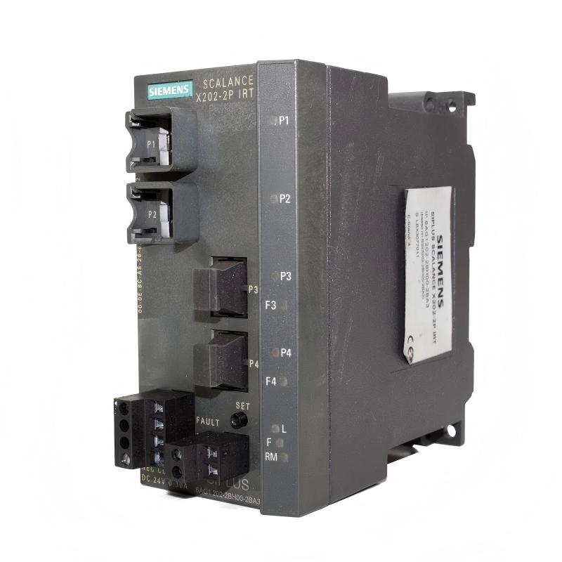
The Siemens 6AG1202-2BH00-2BA3 Digital Output Module is an industrial automation component designed to provide discrete output control within a compatible Siemens control system. Digital output modules form an essential part of PLC and distributed I/O architectures because they allow the controller to convert software-based control decisions into physical electrical switching actions.
In an industrial automation application, the PLC continuously evaluates inputs from sensors, switches, transmitters, and other field devices. Based on the programmed control logic, the controller generates output commands. A digital output module receives these commands and interfaces them with external devices such as relays, contactors, solenoid valves, indicator lamps, and other discrete actuators.
The 6AG1202-2BH00-2BA3 is therefore positioned between the automation controller and the controlled field equipment. It provides the output interface required to integrate discrete devices into an automated process.
The listed dimensions are 60 × 125 × 124 mm, and the listed weight is approximately 0.78 kg. Its industrial form factor makes it suitable for control cabinets and automation installations where reliable digital signal switching and organized I/O architecture are required.
Technical Specifications
| Parameter | Specification |
|---|---|
| Manufacturer | Siemens |
| Model | 6AG1202-2BH00-2BA3 |
| Product Type | Digital Output Module |
| Product Family | Siemens SIPLUS / Industrial Automation |
| Primary Function | Discrete output signal control |
| Signal Type | Digital / Discrete |
| System Role | PLC output interface |
| Application | Industrial automation and machine control |
| Installation | Compatible Siemens automation system |
| Dimensions | 60 × 125 × 124 mm |
| Weight | 0.78 kg |
| Typical Applications | Machine control, process automation, equipment control |
Exact channel configuration, output voltage, current capability, electrical isolation, switching characteristics, protection functions, and environmental specifications should be verified against the applicable Siemens product documentation and hardware revision.
What Is the Siemens 6AG1202-2BH00-2BA3?
The Siemens 6AG1202-2BH00-2BA3 is a Digital Output Module used to provide discrete control signals to external equipment.
Digital output modules are commonly used when the required control action has two basic states, such as:
- ON / OFF
- Energized / De-energized
- Open / Closed
- Active / Inactive
- Start / Stop
A simplified control path is:
PLC → Digital Output Module → Field Device
For example, the PLC may determine that a motor contactor should be energized. The control program generates the corresponding digital output command, and the output module provides the interface between the PLC logic and the external control circuit.
The exact electrical behavior depends on the module configuration and connected equipment.
Digital Output Working Principle
A digital output module converts logical commands from the automation controller into electrical output states.
The basic operating sequence is:
Control Program → Output Data → Digital Output Channel → External Circuit → Actuator
When the PLC changes a particular output from its inactive state to its active state, the corresponding output circuit changes state.
Depending on the application and output technology, the external circuit may control:
- Relay coils
- Contactors
- Solenoid valves
- Pilot lamps
- Alarm devices
- Motor-control circuits
- Interposing relays
- Other discrete loads
The module therefore acts as the electrical interface between software logic and physical equipment.
Role in Industrial Automation
The 6AG1202-2BH00-2BA3 can be integrated into a broader PLC-based control architecture.
A typical automation sequence is:
Sensor → Input Module → PLC → Digital Output Module → Actuator
The input side provides the controller with information about the machine or process. The PLC evaluates this information using the programmed control logic.
The output module then executes the resulting discrete command.
For example:
- A sensor detects that a product has reached a particular position.
- The input system sends the signal to the PLC.
- The PLC evaluates the programmed sequence.
- The PLC activates a digital output.
- The digital output module changes the corresponding output state.
- An actuator responds to the command.
This cycle can occur repeatedly throughout an automated production process.
Digital Output vs. Digital Input
Digital input and digital output modules perform complementary functions.
| Module Type | General Function |
|---|---|
| Digital Input | Receives discrete signals from field devices |
| Digital Output | Sends discrete control signals to field devices |
Digital inputs may monitor:
- Push buttons
- Limit switches
- Proximity sensors
- Safety contacts
- Auxiliary contacts
Digital outputs may control:
- Relays
- Contactors
- Solenoid valves
- Indicator lamps
- Alarms
- Other discrete actuators
A complete automation system often requires both types.
Industrial Applications
Factory Automation
Digital output modules are widely used in manufacturing systems where the PLC must control discrete machine functions.
Typical applications include:
- Assembly machines
- Packaging equipment
- Production lines
- Machine tools
- Material handling
- Automated inspection systems
Conveyor Systems
A PLC can use digital outputs to control conveyor-related equipment such as contactors, valves, indicators, and interposing relays.
Packaging Machinery
Packaging machines frequently require numerous discrete control commands for actuators and auxiliary equipment.
A digital output module can provide the interface between the PLC sequence and these devices.
Process Automation
Discrete outputs are also used in process applications for controlling equipment such as:
- Solenoid valves
- Pump control circuits
- Alarm devices
- Motor starters
- Auxiliary equipment
Building and Infrastructure Automation
Where compatible Siemens automation systems are used, digital outputs can control lighting-related equipment, fans, valves, alarms, and other discrete devices.
PLC Integration
The 6AG1202-2BH00-2BA3 is designed to operate as part of an automation architecture rather than as an independent controller.
A simplified configuration is:
PLC / Controller → I/O Communication → Digital Output Module → Field Wiring → Actuator
The PLC determines the desired state of each output according to the application program.
The digital output module then transfers the command into the external electrical circuit.
Correct configuration is important because the engineering software must recognize the module and its intended position within the automation system.
HMI and SCADA Integration
Although the digital output module directly interfaces with field equipment, operators normally interact with the output functions through an HMI or SCADA system.
For example, an operator may use an HMI to:
- Start equipment
- Stop equipment
- Enable an actuator
- Reset an alarm
- Change an operating mode
The HMI sends the operator command to the PLC. The PLC evaluates the command and generates the appropriate output data.
The digital output module then transfers the command to the field device.
This provides a layered architecture:
Operator → HMI → PLC → Digital Output Module → Field Device
Output Load Considerations
Digital output modules must be matched carefully to the electrical characteristics of the connected load.
Before connecting a field device, engineers should verify:
- Output type
- Load voltage
- Load current
- Switching frequency
- Inrush current
- Load inductance
- Required suppression
- Isolation requirements
- Protection requirements
Inductive loads such as relay coils, solenoids, and contactors may require appropriate suppression or interface circuitry.
The exact permissible load characteristics of the 6AG1202-2BH00-2BA3 should be confirmed from the applicable technical documentation.
Installation Guidelines
Before installation, verify:
- Complete Siemens order number
- Hardware revision
- Compatible automation system
- Module position
- Field wiring
- Output load characteristics
- Power arrangement
- Cabinet environmental conditions
The module should be installed according to the requirements of the host Siemens system.
Do not determine compatibility solely from the module’s physical dimensions.
Mechanical Installation
The listed dimensions of the module are:
60 × 125 × 124 mm
These dimensions should be considered when planning the control cabinet.
Allow adequate space for:
- Module mounting
- Field wiring
- Connectors
- Cable bending
- Adjacent modules
- Ventilation
- Maintenance access
- Module replacement
Avoid excessive mechanical force during installation.
Digital Output Wiring
Output wiring should be designed according to the electrical requirements of the connected load.
Before connecting the field device:
- Identify the correct output channel.
- Verify the load type.
- Confirm voltage compatibility.
- Confirm current requirements.
- Check common/reference connections.
- Verify polarity where applicable.
- Install suitable protection or suppression where required.
- Check wiring before energizing the circuit.
Incorrect output wiring can result in malfunction or damage to connected equipment.
Inductive Load Protection
Many industrial actuators are inductive loads.
Examples include:
- Contactors
- Relays
- Solenoid valves
- Electromagnetic actuators
When these devices are switched off, stored energy can generate transient electrical conditions.
Appropriate suppression may therefore be required depending on the output technology and connected load.
The protection method should be selected according to the electrical characteristics of the specific field device and output circuit.
EMC and Electrical Noise
Digital output systems may operate near electrically noisy equipment.
Potential interference sources include:
- Motors
- Variable frequency drives
- Servo drives
- Contactors
- Transformers
- Switching power supplies
Recommended engineering practices include:
- Separate signal and high-power cables where appropriate.
- Maintain organized cabinet wiring.
- Use suitable shielding when required.
- Provide proper grounding.
- Minimize unnecessary cable loops.
- Keep sensitive control wiring away from high-current conductors.
Good EMC design can reduce intermittent output behavior and improve overall system reliability.
Commissioning Procedure
A structured commissioning process helps verify the digital output module and connected equipment.
Step 1: Verify Hardware
Confirm that the installed device is Siemens 6AG1202-2BH00-2BA3.
Step 2: Check Module Installation
Verify mounting, connectors, adjacent modules, and cabinet arrangement.
Step 3: Verify Field Wiring
Check each output connection against the approved electrical drawings.
Step 4: Confirm Load Compatibility
Verify that connected devices are appropriate for the output circuit.
Step 5: Configure the PLC
Confirm that the module is correctly represented in the engineering configuration.
Step 6: Perform Output Tests
Activate individual outputs under controlled commissioning conditions.
Step 7: Check Field Devices
Confirm that the connected actuators respond correctly.
Step 8: Verify HMI and SCADA Commands
If supervisory control is used, verify that operator commands produce the expected PLC and output behavior.
Step 9: Record Results
Document the module identification, wiring, test results, and configuration.
Troubleshooting the Siemens 6AG1202-2BH00-2BA3
Digital output problems should be investigated systematically.
Output Does Not Activate
Possible causes include:
- Incorrect PLC logic
- Incorrect module configuration
- Wiring problem
- Missing power
- Load problem
- Incorrect output channel
- Protection device operation
- Module fault
Start with PLC diagnostics and verify the output command before replacing hardware.
Output Remains Active
Possible causes may include:
- Incorrect control logic
- Forced output state
- Configuration problem
- Wiring error
- External circuit problem
- Output-channel fault
Check the PLC program, diagnostics, and field wiring.
Output Intermittently Drops Out
Possible causes include:
- Power instability
- Loose wiring
- Excessive load
- Electrical interference
- Inductive transients
- Connector problems
- Thermal conditions
Trend the output status and inspect the corresponding field circuit.
Multiple Outputs Fail
If several output channels stop operating simultaneously, investigate common system conditions first.
Possible areas include:
- Module power
- Shared field supply
- PLC communication
- Module configuration
- Common wiring
- Station infrastructure
A common power or configuration problem may affect multiple outputs.
Preventive Maintenance
Regular maintenance helps preserve reliable digital output operation.
Inspect the Module
Check for:
- Physical damage
- Discoloration
- Contamination
- Loose connections
- Signs of overheating
Inspect Output Wiring
Look for:
- Loose terminals
- Damaged cables
- Incorrect routing
- Moisture
- Excessive mechanical stress
Check Connected Loads
Periodically verify that contactors, solenoids, relays, and other actuators remain within their intended operating conditions.
Monitor Diagnostics
Review PLC and system diagnostics for repeated output or module-related faults.
Maintain Cabinet Conditions
Keep the control cabinet within suitable environmental conditions and maintain adequate ventilation.
Replacement and Spare-Part Planning
When replacing a Siemens 6AG1202-2BH00-2BA3 Digital Output Module, verify the complete order number before installation.
Important identification information includes:
- Full Siemens model number
- Hardware revision
- Host automation system
- Module position
- Output configuration
- Field wiring
- Connected load characteristics
The listed dimensions are 60 × 125 × 124 mm, and the listed weight is 0.78 kg.
These values are useful for:
- Spare-parts management
- Shipping
- Cabinet planning
- Maintenance logistics
- Replacement preparation
Physical dimensions alone should not be used to determine electrical or functional compatibility.
Physical Dimensions and Weight
| Physical Parameter | Value |
|---|---|
| Height | 60 mm |
| Width | 125 mm |
| Depth | 124 mm |
| Weight | 0.78 kg |
The compact industrial form factor allows the 6AG1202-2BH00-2BA3 to be integrated into equipment where cabinet space and organized I/O installation are important.
Compatible System Components
A typical Siemens automation system containing a digital output module may include:
| Component | General Function |
|---|---|
| Siemens PLC | Executes application logic |
| Digital Input Module | Acquires discrete field signals |
| Digital Output Module | Controls discrete field devices |
| Analog Input Module | Acquires analog process values |
| Analog Output Module | Generates analog control signals |
| Interface Module | Connects distributed I/O to the network |
| Bus Adapter | Provides communication interface |
| Power Supply | Supplies system operating power |
| HMI | Operator control and visualization |
| SCADA | Supervisory monitoring |
| Relay / Contactor | Interfaces higher-power loads |
| Solenoid Valve | Performs process control action |
The exact system arrangement depends on the application.
Recommended Related Siemens Models
| Model | Product Type | General Application |
|---|---|---|
| 6AG1202-2BH00-2BA3 | Digital Output Module | Discrete actuator control |
| 6AG1134-6JD00-2CA1 | Analog Input Module | Analog process measurement |
| 6AG1195-7HD10-2XA0 | Active Bus Module | Distributed I/O infrastructure |
| 6AG1195-7HG00-2XA0 | Active Bus Module | Modular bus infrastructure |
| 6AG1197-1LB00-4XA0 | Bus Adapter | Industrial communication |
| 6AG1193-6AR00-7AA0 | PROFINET Bus Adapter | Distributed I/O communication |
These components have different functions and should not automatically be treated as direct substitutes for the 6AG1202-2BH00-2BA3.
Engineering Best Practices
Match the Output to the Load
Verify voltage, current, switching behavior, and load type before connecting an actuator.
Protect Inductive Loads
Use an appropriate suppression strategy when required for contactors, relays, and solenoids.
Keep Wiring Organized
Clear wiring makes commissioning and troubleshooting easier.
Verify PLC Configuration
The physical module and engineering configuration should correspond.
Use Controlled Output Testing
During commissioning, activate outputs individually where practical and verify the response of the connected field equipment.
Document Channel Assignments
Maintain updated documentation showing which output channel controls each field device.
Keep Spare Modules Identified
Record exact product numbers and revisions so that replacement components can be selected correctly.
Key Advantages
The Siemens 6AG1202-2BH00-2BA3 Digital Output Module provides several practical benefits within a compatible industrial automation system:
- Dedicated digital output control
- Compact 60 × 125 × 124 mm construction
- Listed weight of 0.78 kg
- Interfaces PLC logic with discrete field equipment
- Suitable for machine and process automation
- Supports organized I/O architecture
- Can control compatible discrete actuators
- Integrates into larger Siemens automation systems
- Supports centralized control through PLC and HMI architectures
- Suitable for industrial control cabinet applications
Technical FAQs
What is the Siemens 6AG1202-2BH00-2BA3?
The Siemens 6AG1202-2BH00-2BA3 is a Digital Output Module designed to interface PLC control commands with compatible discrete field devices.
What does a digital output module do?
It converts digital commands from the automation controller into corresponding output states that can be used to control external electrical devices.
What devices can a digital output module control?
Depending on the output specifications, typical applications include relays, contactors, solenoid valves, indicator lamps, alarms, and other discrete actuators.
What are the dimensions of the 6AG1202-2BH00-2BA3?
The listed dimensions are 60 × 125 × 124 mm.
How much does the module weigh?
The listed weight is approximately 0.78 kg.
Is the 6AG1202-2BH00-2BA3 a PLC CPU?
No. It is an output interface module. The PLC or controller executes the application logic.
Can the module directly control any industrial actuator?
Not necessarily. The voltage, current, load type, switching requirements, and protection requirements of the output module must be matched to the connected device.
Why are inductive loads important?
Devices such as relays, contactors, and solenoid valves can generate electrical transients when switched. Appropriate suppression may be required depending on the circuit design.
What should be checked if an output does not work?
Check the PLC command, module configuration, output power, wiring, channel assignment, connected load, and system diagnostics before replacing the module.
Can another Siemens digital output module replace this model?
A different Siemens output module should not automatically be considered interchangeable. The complete order number, electrical specifications, hardware revision, system architecture, and field wiring should be verified.
Conclusion
The Siemens 6AG1202-2BH00-2BA3 Digital Output Module is an industrial automation component designed to provide a controlled interface between PLC logic and compatible discrete field equipment. Digital output modules are essential in many automation systems because they transform software-based control decisions into physical switching actions for actuators and auxiliary equipment.
With listed dimensions of 60 × 125 × 124 mm and a weight of 0.78 kg, the module provides a compact solution for industrial control cabinets and automation installations.
Successful operation depends on correct module configuration, suitable field wiring, compatible output loads, appropriate protection for inductive devices, proper EMC practices, and systematic commissioning. When a digital output fault occurs, the complete path from PLC logic through the output module and field wiring to the actuator should be examined.
For maintenance and replacement, the complete 6AG1202-2BH00-2BA3 identification should be verified before installation. Physical similarity with another Siemens output module does not by itself establish electrical or functional compatibility.