

ProductPRODUCT
Featured products
Contact Us
- Allen Bradley
- 20G1ALD617AN4NNNNN
- PowerFlex AC Drive
- USA
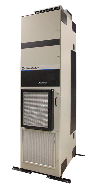
- 2453 mm high × 600 mm wide × 800 mm
- 725kg
- Xiamen, China
- New & In Stock
- T/T, PayPal, Western Union
- 1 Year
- 1-3 Working Days
- DHL, UPS, TNT, FedEx and EMS.
- 24-Hour Service
- COO
- 3
Our advantage

Global Logistics
We have a 10-year logistics and express cooperation agreement, so our products can be shipped to any place in the world.

Brand new and original
Our products are imported in bulk from the place of origin. Because of the cooperative relationship, our products are all original and 100% new.

24-hour service
We provide 7*24 hours service to our customers. We will be there whenever you need us.

Price advantage
All our products are priced very favorably because we have our own warehouse and supply.
| Company Information | |||
| [email protected] | |||
| Mobile | +8615980777398 | ||
| +8615980777398 | |||
| 15980777398 |
Allen-Bradley 20G1ALD617AN4NNNNN PowerFlex 755 Air-Cooled AC Drive
1. Product Overview
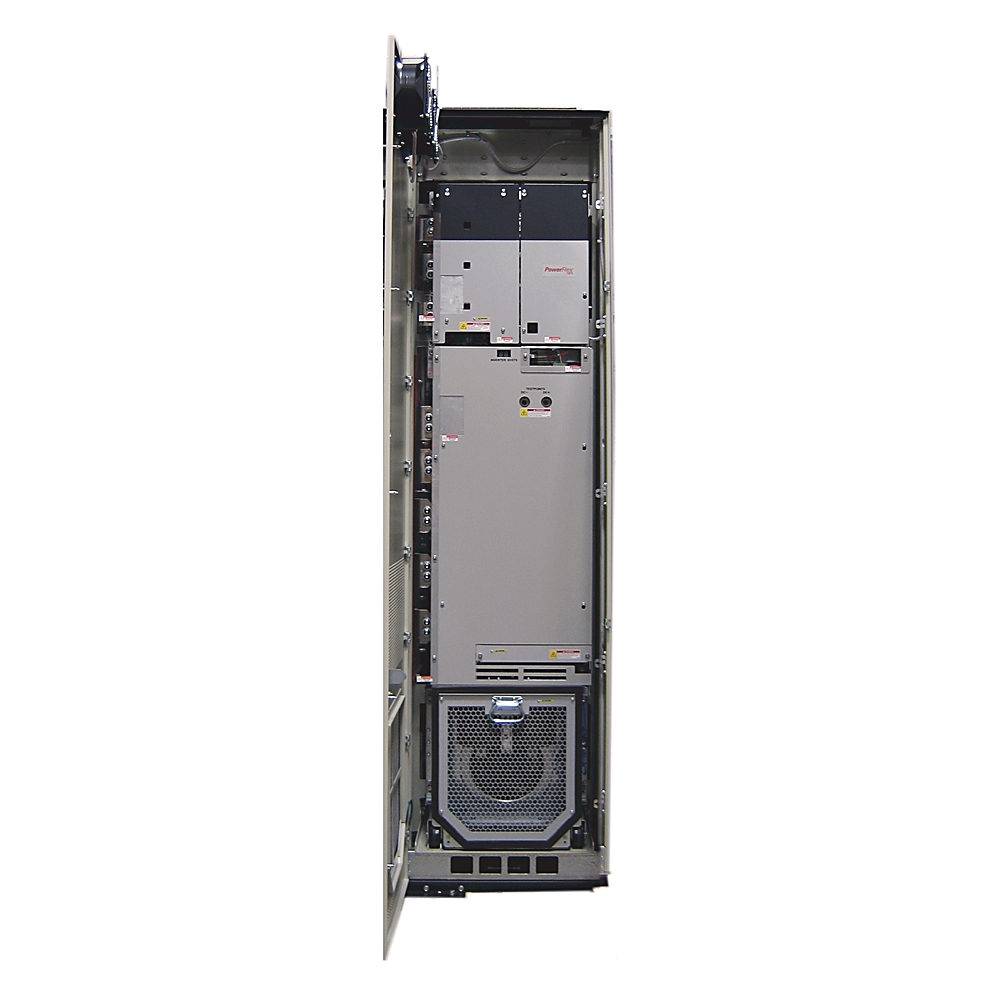
The Allen-Bradley 20G1ALD617AN4NNNNN is a high-power PowerFlex 755 Air-Cooled AC Drive designed for large industrial motor-control applications.
It belongs to the PowerFlex 755 family and is intended for large three-phase AC motors where conventional small or medium-size variable-frequency drives are not sufficient.
The drive combines a high current capacity with an industrial-scale air-cooled power section, network-based automation capabilities, programmable motor control, diagnostics, and flexible installation options.
The 617 A current class places this model in the large Frame 8 range. It is suitable for demanding applications such as large pumps, fans, blowers, conveyors, compressors, process machinery, material-handling systems, and other high-power rotating equipment.
The 20G1ALD617AN4NNNNN is particularly appropriate when the motor-control system needs to be integrated into a larger plant automation architecture rather than operated as an independent stand-alone speed controller.
2. Brand and Product Series
| Item | Specification |
|---|---|
| Brand | Allen-Bradley |
| Product family | PowerFlex |
| Product series | PowerFlex 755 |
| Product type | Air-Cooled AC Drive |
| Model | 20G1ALD617AN4NNNNN |
| Drive class | High-power industrial AC drive |
| Construction | Air cooled |
| Frame | Frame 8 |
| Current class | 617 A |
| Voltage class | 480 VAC |
| Phase | Three phase |
| Primary function | Variable-frequency motor control |
| Typical installation | Large industrial cabinet / MCC-style system |
| Typical applications | Pumps, fans, conveyors, compressors, process machinery |
The PowerFlex 755 series is intended for applications where motor control, automation integration, diagnostics, configuration flexibility, and high-power operation are all important.
It is considerably larger in physical and electrical scale than compact machine-level drives.
3. Main Technical Parameters
| Parameter | Specification |
|---|---|
| Model | 20G1ALD617AN4NNNNN |
| Brand | Allen-Bradley |
| Series | PowerFlex 755 |
| Product type | Air-Cooled AC Drive |
| Input voltage | 480 VAC class |
| Input phase | 3 phase |
| Current rating | 617 A |
| Light-Duty rating | Approximately 600 HP |
| Normal-Duty rating | Approximately 500 HP |
| Heavy-Duty rating | Approximately 400 HP |
| Frame size | Frame 8 |
| Cooling method | Forced air cooling |
| Input configuration | AC input with precharge |
| External DC terminals | No external DC terminals in this configuration |
| Filtering | Filtered configuration |
| CM configuration | Configuration-dependent CM jumper arrangement |
| Dynamic braking | No integrated dynamic-braking configuration identified |
| Enclosure style | Type 1 / IP20 class |
| Cabinet depth class | Approximately 800 mm MCC-style |
| Communication | Industrial automation/network integration |
| Typical network architecture | EtherNet/IP-based |
| Motor type | Large three-phase AC motors |
| Installation | Floor/cabinet/MCC-style industrial installation |
| Approximate width | 600 mm class |
| Approximate height | 2453 mm class |
| Approximate depth | 800 mm class |
| Approximate weight | Approximately 620–725 kg |
| Application class | Large industrial motor control |
| Mounting orientation | Vertical |
| Cooling environment | Industrial electrical room or suitable cabinet |
| Maintenance requirement | Periodic inspection of cooling, electrical connections and ventilation |
The exact mechanical dimensions and weight can vary with the complete drive configuration, cabinet arrangement, factory options, accessories and shipping configuration.
For engineering, lifting and installation work, the final mechanical drawing and shipping documentation should always be used as the controlling reference.
4. Model Number Interpretation
The catalog number 20G1ALD617AN4NNNNN identifies a specific configuration within the PowerFlex 755 family.
The 20G1 portion identifies the PowerFlex 755 drive family.
The ALD portion identifies the relevant air-cooled 755 configuration.
The 617 portion indicates the 617 A current class.
The AN4 section identifies the particular factory configuration within this current class.
The remaining configuration characters represent additional product configuration information.
This is important because a large PowerFlex drive should not be selected only by looking at horsepower.
Two drives may have the same voltage and current rating but have different factory configurations, operator-interface arrangements, cabinet configurations, filtering options, braking arrangements or other options.
For replacement projects, the complete catalog number should therefore be compared.
5. 617 A Current Capacity
The 617 A rating is the central electrical characteristic of this model.
A drive in this current range is designed for large industrial motors and high-power mechanical equipment.
The associated power classes are approximately:
| Duty | Approximate Motor Rating |
|---|---|
| Light Duty | 600 HP |
| Normal Duty | 500 HP |
| Heavy Duty | 400 HP |
The actual application rating should be determined from the motor nameplate current, duty cycle, overload requirement, operating temperature, switching conditions and application characteristics.
A motor’s horsepower alone is not sufficient for final drive selection.
6. Light-Duty Operation
Light-Duty operation is generally used for applications where the motor does not require the same overload capability as a high-torque industrial machine.
Typical examples include large centrifugal fans and certain centrifugal pumps.
The approximately 600 HP Light-Duty class provides substantial motor capacity for large process equipment.
For applications with relatively stable load torque and modest overload requirements, this rating can be particularly useful.
7. Normal-Duty Operation
The approximately 500 HP Normal-Duty rating provides a useful reference for general industrial applications.
Typical applications can include:
- Large pumps.
- Fans.
- Blowers.
- Conveyors.
- Process machinery.
- Material-handling systems.
- General industrial production equipment.
Normal-Duty applications generally require more capability than simple low-load fan applications but may not require the highest overload performance associated with Heavy-Duty machinery.
8. Heavy-Duty Operation
The approximately 400 HP Heavy-Duty rating is relevant when the application places greater demands on the drive.
Heavy-Duty applications can involve:
- High starting torque.
- Frequent acceleration.
- Frequent deceleration.
- Variable mechanical loading.
- High inertia.
- Rapid load changes.
- Demanding production cycles.
Examples include heavy conveyors, mixers, extruders, crushers and other process machinery.
The correct duty class should always be selected according to the actual load profile.
9. 480 VAC Three-Phase Input
The 20G1ALD617AN4NNNNN is designed for the 480 VAC industrial voltage class and three-phase operation.
This voltage class is commonly associated with large industrial motors.
For high-power motors, a higher supply voltage helps keep current within a manageable range compared with transferring the same amount of power at a much lower voltage.
At the 617 A level, electrical installation becomes a significant engineering project.
The incoming power system, disconnecting equipment, protective devices, conductors, grounding, cabinet construction and short-circuit considerations all need to be properly coordinated.
10. AC Input with Precharge
The drive uses an AC input with precharge configuration.
A large variable-frequency drive contains a DC-link section with substantial energy-storage components.
When the drive is initially energized, the precharge function manages the charging process of the DC bus.
This prevents an uncontrolled initial charging current from being imposed directly on the power system.
For a drive in the 617 A class, controlled precharge is an important part of the overall power-conversion architecture.
11. No External DC Terminals
The specified configuration is associated with a no-external-DC-terminal arrangement.
This means the drive is not intended to be treated as a general-purpose externally accessible DC-bus connection point.
Applications involving common DC buses, regenerative power systems or external DC sources should therefore be evaluated against the exact drive configuration before equipment is selected.
The internal DC bus remains an essential part of the normal AC-to-DC-to-AC conversion process.
12. Air-Cooled Design
The 20G1ALD617AN4NNNNN uses an air-cooled construction.
At this power level, the semiconductor switching devices and other internal components generate substantial heat.
Forced-air cooling removes this heat and helps maintain acceptable internal operating temperatures.
Proper ventilation is therefore a major part of the installation.
The following conditions should be considered:
- Adequate airflow.
- Correct cabinet ventilation.
- Sufficient service clearance.
- Clean air passages.
- Appropriate ambient temperature.
- Proper cooling-fan operation.
- Regular maintenance.
A large air-cooled drive should never be installed in a poorly ventilated enclosure simply because there appears to be enough physical space.
13. Frame 8 Construction
The Frame 8 architecture is designed for high-power applications.
The physical size is substantially greater than that of compact PowerFlex products.
The larger frame accommodates:
- High-current power components.
- Large electrical connections.
- Cooling equipment.
- Power bus structures.
- Control hardware.
- Protective components.
- Mechanical support structures.
Because of this, Frame 8 installation should be planned as a complete industrial power installation.
14. Industrial Network Integration
One of the useful characteristics of the PowerFlex 755 platform is its ability to participate in a larger automation system.
The drive can be incorporated into an industrial network architecture so that the control system can exchange operating commands and drive information.
Typical information may include:
- Start command.
- Stop command.
- Speed reference.
- Output frequency.
- Motor current.
- Drive status.
- Fault status.
- Warning status.
- Operating condition.
- Diagnostic information.
This can reduce the amount of point-to-point hardwired control required in a large installation.
15. Automation System Integration
In a modern factory, the drive may operate as one part of a complete automation system.
For example, a PLC can provide the speed reference while receiving motor current and drive-status information.
A supervisory system can monitor multiple drives simultaneously.
Maintenance personnel can also use drive diagnostics to identify abnormal operating conditions.
This becomes particularly useful when a facility contains dozens or hundreds of motor-driven machines.
16. Filtering and EMC Considerations
The specified configuration includes a filtered arrangement.
Filtering is important in large industrial drive installations because high-frequency switching can introduce electrical noise into the surrounding system.
A properly engineered installation considers:
- Motor cable routing.
- Control cable routing.
- Grounding.
- Shielding.
- Cabinet bonding.
- Communication wiring.
- EMC filter configuration.
- Cable length.
- Motor insulation requirements.
Filtering should be considered as part of the complete electrical system rather than as an isolated drive feature.
17. CM Jumper Configuration
The configuration suffix also relates to the common-mode filtering arrangement.
The exact CM jumper state is important because it can affect the relationship between the drive’s internal filtering network and the grounding system.
This should be matched to the actual power-system grounding arrangement.
Engineers should avoid changing filter or CM-jumper configuration without checking the electrical installation requirements.
18. Dynamic Braking
The requested configuration is not identified as having an integrated dynamic-braking arrangement.
This does not mean that the application can never perform controlled deceleration.
It means that if the machine requires substantial regenerative energy dissipation, the complete braking solution needs to be evaluated separately.
Applications with:
- High-inertia loads.
- Frequent stopping.
- Rapid deceleration.
- Overhauling loads.
- Vertical lifting.
may require additional braking analysis.
The required braking method depends heavily on the machine’s mechanical characteristics.
19. Dimensions and Weight
The physical size of this drive is one of the most important differences between the PowerFlex 755 high-power configuration and compact VFD products.
A practical preliminary planning range is shown below.
| Mechanical Parameter | Approximate Value |
|---|---|
| Model | 20G1ALD617AN4NNNNN |
| Width | Approximately 600 mm |
| Height | Approximately 2453 mm |
| Depth | Approximately 800 mm |
| Approximate weight | 620–725 kg |
| Installation style | Large floor/cabinet installation |
| Orientation | Vertical |
| Frame | Frame 8 |
| Cooling | Forced air |
| Cabinet concept | MCC-style / industrial cabinet |
The weight range should be considered a planning allowance rather than a guaranteed shipping weight.
Actual weight can change according to the final factory configuration, cabinet structure, options and packaging.
For transportation, lifting and floor-loading calculations, the final mechanical documentation should be used.
20. Mechanical Installation
A height of roughly 2.45 m means that the installation area must provide adequate vertical clearance.
The approximate 800 mm depth also requires a sufficiently deep cabinet or MCC arrangement.
The equipment weight can approach several hundred kilograms, so ordinary manual handling is not appropriate.
A suitable lifting and transportation plan should be prepared before delivery.
Floor loading should also be checked.
Maintenance access is equally important.
The drive should not simply be installed wherever it physically fits.
Technicians need sufficient space to inspect cooling components, electrical connections, control wiring and other serviceable components.
21. Main Applications
The 20G1ALD617AN4NNNNN can be used in a wide range of high-power industrial applications.
Its major application categories include:
- Large pumping systems.
- Industrial fans.
- Large blowers.
- Conveyor systems.
- Material-handling equipment.
- Compressors.
- Process machinery.
- Mixers.
- Extruders.
- Industrial production lines.
- Water and wastewater systems.
- Cooling systems.
- Mining equipment.
- Cement and aggregate equipment.
- Steel and metal-processing equipment.
22. Large Pump Applications
Large pumps are a natural application for a high-power variable-frequency drive.
A pump does not always need to operate at maximum speed.
When process demand changes, motor speed can be adjusted accordingly.
The drive can therefore become part of the flow-control system.
Typical installations include:
- Water-treatment plants.
- Industrial water circulation.
- Cooling-water systems.
- Process-water systems.
- Large irrigation systems.
- Industrial fluid transfer.
- Municipal pumping.
Pump applications should be evaluated using the actual pump curve and system curve.
23. Fan and Blower Applications
Large fans and blowers frequently operate under changing process requirements.
A variable-frequency drive allows fan speed to be adjusted.
Applications can include:
- Industrial ventilation.
- Furnace air systems.
- Process exhaust.
- Dust collection.
- Cooling air.
- Combustion air.
- Large air-handling systems.
- Industrial HVAC.
For centrifugal fans, the relationship between speed and airflow makes variable-speed control particularly useful.
24. Conveyor Applications
Large conveyors can benefit from controlled acceleration.
A large conveyor has considerable mechanical inertia.
Starting the motor too aggressively can transmit shock through the gearbox, coupling, belt and supporting structure.
A variable-frequency drive can provide a programmed acceleration ramp.
This allows the motor to gradually reach operating speed.
The drive can also provide controlled stopping.
For long conveyors, the acceleration and deceleration profile should be designed together with the mechanical system.
25. Compressor Applications
Large compressors may require stable speed control and careful acceleration.
The drive can be considered for compressor applications where variable-speed operation is appropriate.
Typical design considerations include:
- Starting torque.
- Acceleration time.
- Minimum speed.
- Maximum speed.
- Motor cooling.
- Process pressure.
- Mechanical resonance.
- Load changes.
- Deceleration behavior.
The drive must be selected against the actual compressor motor current and operating profile.
26. Mining and Material Handling
Large mining and material-handling systems can involve high-power motors operating continuously.
Examples include:
- Ore conveyors.
- Crushers.
- Bulk material systems.
- Transfer conveyors.
- Aggregate equipment.
- Cement plants.
- Port handling equipment.
These machines often benefit from controlled acceleration and integrated monitoring.
The PowerFlex 755 architecture can also fit into larger plant automation systems where multiple high-power drives must be coordinated.
27. Process Machinery
Large mixers, extruders and other process machines can require precise motor-speed control.
In these applications, motor speed can directly affect:
- Production rate.
- Material quality.
- Mixing conditions.
- Product consistency.
- Process temperature.
- Mechanical loading.
The drive can therefore function as part of the process-control strategy rather than simply as a motor starter.
28. Product Advantages
28.1 High Current Capacity
The 617 A rating gives the drive the electrical capacity required by very large motors.
This makes it suitable for applications where smaller drives would be electrically undersized.
28.2 Large Industrial Architecture
The Frame 8 construction is designed for high-power applications.
The large enclosure provides space for substantial power-conversion hardware and cooling equipment.
28.3 Flexible Motor Control
Variable-frequency control allows motor speed to be adjusted to the actual process requirement.
This can be valuable in pumps, fans, conveyors and process equipment.
28.4 Controlled Starting
A large motor can impose substantial electrical and mechanical stress during starting.
The drive provides a controlled acceleration profile rather than applying full-speed operation immediately.
28.5 Controlled Stopping
The motor can also be decelerated according to a programmed ramp.
This can reduce mechanical shock and provide more predictable machine behavior.
28.6 Automation Integration
The PowerFlex 755 platform can be integrated into an industrial automation network.
This makes it possible to combine drive control with PLC, HMI and supervisory control systems.
28.7 Diagnostic Capability
Drive operating information and fault information can be incorporated into the plant maintenance strategy.
This can help technicians identify abnormal operating conditions.
28.8 Suitable for Large Continuous Processes
The large current rating and industrial construction make this model suitable for continuous-duty industrial machinery when the electrical and thermal conditions are correctly engineered.
29. Energy Management Applications
Variable-speed operation can provide opportunities to reduce unnecessary motor operation, particularly in variable-torque applications.
Large fans and centrifugal pumps are common examples.
The actual energy result depends on:
- Operating hours.
- Load profile.
- Required flow.
- Required pressure.
- Motor efficiency.
- Pump/fan efficiency.
- Control strategy.
- System resistance.
Therefore, the drive itself should not be treated as a guarantee of a specific energy saving.
The benefit comes from matching motor speed to actual process demand.
30. Maintenance Advantages
A network-integrated industrial drive can provide useful operating information for maintenance personnel.
For example, the control system may be able to identify:
- Drive faults.
- Motor-current abnormalities.
- Overtemperature conditions.
- Communication faults.
- Operating-state changes.
- Repeated trips.
This can make troubleshooting more systematic.
Preventive maintenance should still include physical inspection.
Cooling fans, air passages, cabinet ventilation and electrical connections require appropriate periodic inspection.
31. Installation Environment
The drive should be installed in an environment appropriate for large industrial electrical equipment.
Important considerations include:
- Ambient temperature.
- Humidity.
- Dust.
- Corrosive atmosphere.
- Altitude.
- Ventilation.
- Electrical pollution.
- Cabinet cleanliness.
- Vibration.
- Maintenance access.
A clean, dry and adequately ventilated electrical environment is particularly important for air-cooled high-power equipment.
32. Electrical System Design
At 617 A, the upstream electrical system deserves careful engineering.
The following items should be evaluated:
| System Item | Engineering Consideration |
|---|---|
| Incoming voltage | Confirm 480 VAC system |
| Phase | Confirm three-phase supply |
| Current capacity | Confirm available supply capacity |
| Protection | Coordinate upstream protection |
| Disconnect | Provide appropriate isolation |
| Grounding | Engineer grounding and bonding |
| Motor cables | Size for actual current and installation method |
| EMC | Consider routing and shielding |
| Harmonics | Evaluate complete plant electrical system |
| Short-circuit rating | Confirm system coordination |
| Cabinet ventilation | Ensure adequate cooling airflow |
| Maintenance | Provide safe service access |
33. Motor Selection
The drive should be matched to the actual motor.
Important motor information includes:
- Rated voltage.
- Full-load current.
- Rated horsepower.
- Rated frequency.
- Base speed.
- Motor service factor.
- Motor insulation system.
- Motor cooling method.
- Encoder or feedback requirements.
- Starting torque requirements.
The motor nameplate current is particularly important.
A 500 HP motor, for example, should not automatically be paired with a drive simply because the drive is labeled as a 500 HP unit.
The current requirement and duty profile must also match.
34. Control-System Integration
The drive can be integrated into a larger industrial control architecture.
A typical system can contain:
PLC → Industrial Network → PowerFlex 755 → Large AC Motor → Mechanical Load
The PLC can control speed references and operating commands.
The drive performs the power conversion and motor control.
The motor provides the mechanical output.
The process equipment consumes that mechanical power.
Feedback from the drive and process can then be returned to the PLC or supervisory system.
This creates a coordinated control structure.
35. Recommended Related Models
The following five models are useful related choices within the PowerFlex 755 family.
| Model | Current Class | Light Duty | Normal Duty | Heavy Duty | Relationship |
|---|---|---|---|---|---|
| 20G1ALD545AN0NNNNN | 545 A | 500 HP | 450 HP | 350 HP | Lower-current related model |
| 20G1ALD617AN0NNNNN | 617 A | 600 HP | 500 HP | 400 HP | Same current class, different configuration |
| 20G1ALD617AN2NNNNN | 617 A | 600 HP | 500 HP | 400 HP | Same current class, related configuration |
| 20G1ALD617JN0NNNNN | 617 A | 600 HP | 500 HP | 400 HP | Same current class, alternate configuration |
| 20G1ALD710AN0NNNNN | 710 A | 650 HP | 600 HP | 450 HP | Higher-current related model |
The 617 A models are especially relevant when the existing application is already designed around the 617 A class.
The 545 A model provides a lower-current option.
The 710 A model provides additional current capacity for applications with higher requirements.
36. Related Model Parameter Comparison
| Model | Voltage | Current | LD | ND | HD | Frame |
|---|---|---|---|---|---|---|
| 20G1ALD545AN0NNNNN | 480 VAC | 545 A | 500 HP | 450 HP | 350 HP | 8 |
| 20G1ALD617AN0NNNNN | 480 VAC | 617 A | 600 HP | 500 HP | 400 HP | 8 |
| 20G1ALD617AN2NNNNN | 480 VAC | 617 A | 600 HP | 500 HP | 400 HP | 8 |
| 20G1ALD617AN4NNNNN | 480 VAC | 617 A | 600 HP | 500 HP | 400 HP | 8 |
| 20G1ALD617JN0NNNNN | 480 VAC | 617 A | 600 HP | 500 HP | 400 HP | 8 |
| 20G1ALD710AN0NNNNN | 480 VAC | 710 A | 650 HP | 600 HP | 450 HP | 8 |
The same-current models should not automatically be considered identical.
Their suffixes indicate different configurations.
For replacement work, the complete model number should be checked against the control architecture and installed options.
37. Five Same-Brand Popular Models
For comparison with other products in the same brand portfolio, the following models cover different drive sizes and application levels.
| Model | Product Family | General Voltage Class | General Application | Product Scale |
|---|---|---|---|---|
| 25B-D010N104 | PowerFlex 525 | Low-voltage industrial | Compact machine control | Small/medium |
| 25C-D010N103 | PowerFlex 527 | Low-voltage industrial | Networked machine control | Small/medium |
| 20F11NC2P1JA0NNNNN | PowerFlex 753 | Low-voltage industrial | Industrial motor control | Medium/large |
| 20F11NC8P0JA0NNNNN | PowerFlex 753 | Low-voltage industrial | Larger industrial applications | Large |
| 20G1ALD617AN4NNNNN | PowerFlex 755 | 480 VAC class | High-power industrial motor control | Very large |
These models belong to different product classes and should not be treated as direct one-for-one substitutes.
The smaller PowerFlex products are more appropriate for compact machinery.
The PowerFlex 753 and PowerFlex 755 families are designed for larger industrial applications.
The requested 20G1ALD617AN4NNNNN is specifically a high-power Frame 8 product.
38. Comparison of Application Scale
| Product | Typical Application Scale | Typical Equipment |
|---|---|---|
| 25B-D010N104 | Small/medium | Machine conveyors, pumps, fans |
| 25C-D010N103 | Small/medium | Networked machine automation |
| 20F11NC2P1JA0NNNNN | Medium/large | Industrial pumps, fans, conveyors |
| 20F11NC8P0JA0NNNNN | Large | Industrial production equipment |
| 20G1ALD617AN4NNNNN | Very large | Large pumps, fans, conveyors, compressors |
The requested 617 A PowerFlex 755 configuration is intended for an entirely different physical and electrical scale from the compact 25-series drives.
39. Application Selection Table
| Application | Typical Requirement | Suitability of 20G1ALD617AN4NNNNN |
|---|---|---|
| Large centrifugal pump | Variable speed / large motor | Suitable when current and duty match |
| Large fan | Variable speed / continuous operation | Suitable |
| Large blower | High-power motor control | Suitable |
| Conveyor | Controlled acceleration | Suitable |
| Mining conveyor | High torque / large motor | Suitable when duty is correctly selected |
| Compressor | Controlled acceleration and speed | Application dependent |
| Mixer | High torque | Application dependent |
| Extruder | Stable speed / process control | Application dependent |
| Material handling | Large motor / controlled operation | Suitable when correctly sized |
| Industrial process line | Networked motor control | Suitable |
40. Product Advantages in Practical Industrial Use
| Feature | Industrial Benefit |
|---|---|
| 617 A rating | Supports very large motor loads |
| 480 VAC three-phase | Fits common high-power industrial systems |
| Frame 8 | Provides large power-handling capacity |
| Air cooling | Practical for large electrical installations |
| Variable-frequency operation | Adjustable motor speed |
| Controlled acceleration | Reduced mechanical starting shock |
| Controlled deceleration | Predictable stopping |
| Network integration | Easier plant-level automation |
| Diagnostics | Supports troubleshooting |
| Flexible duty selection | Allows matching to load requirements |
| Filtered configuration | Supports electrical-noise management |
| Large industrial construction | Suitable for major equipment |
41. Dimensions and Weight Planning
For purchasing and installation planning, the following figures can be used as preliminary values.
| Mechanical Specification | Planning Value |
|---|---|
| Model | 20G1ALD617AN4NNNNN |
| Height | Approx. 2453 mm |
| Width | Approx. 600 mm |
| Depth | Approx. 800 mm |
| Weight | Approx. 620–725 kg |
| Frame | 8 |
| Cooling | Air cooled |
| Installation | Vertical |
| Cabinet arrangement | MCC-style / large industrial cabinet |
These values should be used for preliminary planning only.
The actual delivered equipment may have different dimensions or weight depending on the complete configuration.
This is particularly important for Frame 8 equipment because options, cabinet sections, packaging and associated power equipment can affect the final installation envelope.
42. Shipping and Handling
The weight of this equipment means transportation planning is important.
The equipment should be protected against:
- Impact.
- Excessive vibration.
- Moisture.
- Improper lifting.
- Incorrect orientation.
- Uncontrolled movement.
A suitable industrial lifting method should be selected based on the final shipping weight.
The installation location should also be checked for floor loading.
For replacement projects, the removal of the old drive should be planned at the same time as the installation of the new equipment.
43. Commissioning Considerations
Before energizing the drive, the engineering team should verify:
- Input voltage.
- Phase arrangement.
- Grounding.
- Motor wiring.
- Motor nameplate data.
- Control wiring.
- Communication wiring.
- Cooling airflow.
- Cabinet clearances.
- Protective devices.
- Motor rotation.
- Acceleration parameters.
- Deceleration parameters.
- Current limits.
- Motor-control mode.
- Network addressing.
- Fault-handling strategy.
The commissioning process should begin with appropriate low-risk testing before the equipment is placed into full production operation.
44. Maintenance Planning
For a large air-cooled drive, maintenance should include inspection of the cooling system.
Dust, dirt and other contamination can reduce airflow.
Cooling fans should be monitored for abnormal noise or performance.
Electrical connections should be checked according to the plant maintenance procedure.
Repeated drive faults should be investigated rather than simply reset.
A repeated trip can indicate:
- Motor problems.
- Mechanical overload.
- Cooling problems.
- Electrical supply problems.
- Incorrect parameters.
- Communication issues.
- Application-related problems.
45. Why the Complete Catalog Number Matters
The difference between:
20G1ALD617AN0NNNNN
20G1ALD617AN2NNNNN
20G1ALD617AN4NNNNN
and
20G1ALD617JN0NNNNN
is not merely cosmetic.
These catalog numbers represent different configuration arrangements within the same broad PowerFlex 755 family.
When purchasing a replacement, the exact suffix should therefore be checked against:
- Operator interface.
- Input protection.
- Filter configuration.
- CM configuration.
- Control-power requirements.
- Braking requirements.
- Cabinet arrangement.
- Network configuration.
- Existing control-system design.
This prevents the common mistake of purchasing a drive based only on current and horsepower.
46. Recommended Selection Procedure
A practical selection procedure can be organized as follows.
Step 1 – Confirm Motor Voltage
Verify that the motor and supply system are compatible with the 480 VAC class.
Step 2 – Confirm Motor Current
Use the motor nameplate current as a primary sizing reference.
Step 3 – Determine Duty
Determine whether the application is Light Duty, Normal Duty or Heavy Duty.
Step 4 – Evaluate Acceleration
Determine the required acceleration time and starting torque.
Step 5 – Evaluate Deceleration
Determine whether regenerative or dynamic braking is required.
Step 6 – Check Communication
Determine how the drive will communicate with the PLC or supervisory system.
Step 7 – Check Mechanical Space
Verify the cabinet depth, height, width and service clearance.
Step 8 – Check Weight
Verify floor loading, lifting requirements and transportation arrangements.
Step 9 – Check Environmental Conditions
Review temperature, dust, humidity, altitude and ventilation.
Step 10 – Confirm Complete Catalog Number
Only after the electrical, mechanical and control requirements have been checked should the final configuration be confirmed.
47. Detailed Product Specification Summary
| Specification | Value |
|---|---|
| Brand | Allen-Bradley |
| Product family | PowerFlex |
| Series | PowerFlex 755 |
| Model | 20G1ALD617AN4NNNNN |
| Product type | Air-Cooled AC Drive |
| Voltage class | 480 VAC |
| Phase | Three phase |
| Current rating | 617 A |
| Light Duty | Approximately 600 HP |
| Normal Duty | Approximately 500 HP |
| Heavy Duty | Approximately 400 HP |
| Frame | Frame 8 |
| Input | AC |
| Precharge | Included in AC input configuration |
| External DC terminals | None in this configuration |
| Cooling | Forced air |
| Filtering | Filtered configuration |
| Enclosure | Type 1 / IP20 class |
| Cabinet depth | Approximately 800 mm class |
| Network integration | Industrial automation capable |
| Typical network | EtherNet/IP architecture |
| Dynamic braking | No integrated DB configuration |
| Approximate height | 2453 mm |
| Approximate width | 600 mm |
| Approximate depth | 800 mm |
| Approximate weight | 620–725 kg |
| Mounting | Large industrial floor/cabinet installation |
| Typical applications | Pumps, fans, conveyors, compressors, process machinery |
| Application level | High-power industrial |
| Motor type | Three-phase AC motor |
| Duty selection | LD / ND / HD |
48. Five Closely Related Models – Final Comparison
| Model | Current | LD | ND | HD | Frame | Relationship |
|---|---|---|---|---|---|---|
| 20G1ALD545AN0NNNNN | 545 A | 500 HP | 450 HP | 350 HP | 8 | Lower-current version |
| 20G1ALD617AN0NNNNN | 617 A | 600 HP | 500 HP | 400 HP | 8 | Same current class |
| 20G1ALD617AN2NNNNN | 617 A | 600 HP | 500 HP | 400 HP | 8 | Same current class |
| 20G1ALD617JN0NNNNN | 617 A | 600 HP | 500 HP | 400 HP | 8 | Same current class |
| 20G1ALD710AN0NNNNN | 710 A | 650 HP | 600 HP | 450 HP | 8 | Higher-current version |
49. Five Same-Brand Models – Final Comparison
| Model | Series | Application Scale | Main Application |
|---|---|---|---|
| 25B-D010N104 | PowerFlex 525 | Small/medium | Machine motor control |
| 25C-D010N103 | PowerFlex 527 | Small/medium | Networked machine control |
| 20F11NC2P1JA0NNNNN | PowerFlex 753 | Medium/large | Industrial motor control |
| 20F11NC8P0JA0NNNNN | PowerFlex 753 | Large | Industrial equipment |
| 20G1ALD617AN4NNNNN | PowerFlex 755 | Very large | High-power motor control |
50. Final Product Description
The Allen-Bradley 20G1ALD617AN4NNNNN is a high-power PowerFlex 755 Air-Cooled AC Drive intended for demanding industrial motor-control applications.
Its 617 A current rating, 480 VAC three-phase architecture, Frame 8 construction, air-cooled power section and industrial automation capabilities make it suitable for large motors and high-power mechanical systems.
The drive can be applied to large pumps, fans, blowers, conveyors, compressors, process machines, material-handling equipment, mining systems, cement equipment, water systems and other industrial machinery where controlled motor operation is required.
Its variable-frequency architecture allows motor speed to be adjusted according to process requirements.
For conveyors and high-inertia machinery, controlled acceleration and deceleration can help manage mechanical stress.
For pumps and fans, variable-speed operation can provide a practical way to match motor operation to changing process demand.
For plant automation, the drive can participate in a larger networked control architecture, allowing commands, operating data, alarms and diagnostic information to be exchanged with the control system.
The large Frame 8 construction also means that mechanical planning is critical.
A preliminary installation allowance of approximately 2453 mm high × 600 mm wide × 800 mm deep and approximately 620–725 kg should be considered during early planning.
Because actual mechanical configuration can change the final dimensions and weight, the final equipment documentation should be used for detailed installation, transportation and lifting calculations.
The 20G1ALD617AN4NNNNN is therefore best understood as a complete high-power industrial drive solution rather than simply a high-current frequency converter.
It combines high electrical capacity, large-frame construction, variable-speed motor control, industrial communication capability, filtering, controlled acceleration and a PowerFlex 755 architecture intended for demanding automation environments.
For applications below the 617 A requirement, the 545 A PowerFlex 755 class can be considered.
For applications requiring additional current capacity, the 710 A class provides a larger related option.
Within the 617 A family, the AN0, AN2, AN4 and JN configurations should be differentiated carefully because the suffix represents the specific drive configuration rather than merely a cosmetic catalog-number variation.
For an actual replacement or new installation, the motor nameplate, duty cycle, voltage, current, braking requirements, communication architecture, cabinet dimensions, cooling requirements and complete catalog number should all be checked together.
In large industrial installations, this complete-system approach is important because the drive is only one part of the electrical and mechanical system.