

ProductPRODUCT
Featured products
Contact Us
- Schneider
- TM3AQ2G
- Analog Output Module
- France
- 90 × 23.6 × 70 mm
- 0.1 kg
- Xiamen, China
- New & In Stock
- T/T, PayPal, Western Union
- 1 Year
- 1-3 Working Days
- DHL, UPS, TNT, FedEx and EMS.
- 24-Hour Service
- COO
- 5
Our advantage

Global Logistics
We have a 10-year logistics and express cooperation agreement, so our products can be shipped to any place in the world.

Brand new and original
Our products are imported in bulk from the place of origin. Because of the cooperative relationship, our products are all original and 100% new.

24-hour service
We provide 7*24 hours service to our customers. We will be there whenever you need us.

Price advantage
All our products are priced very favorably because we have our own warehouse and supply.
| Company Information | |||
| [email protected] | |||
| Mobile | +8615980777398 | ||
| +8615980777398 | |||
| 15980777398 |
Product Overview
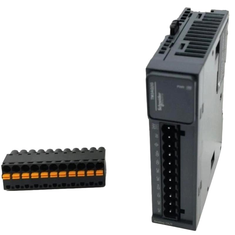
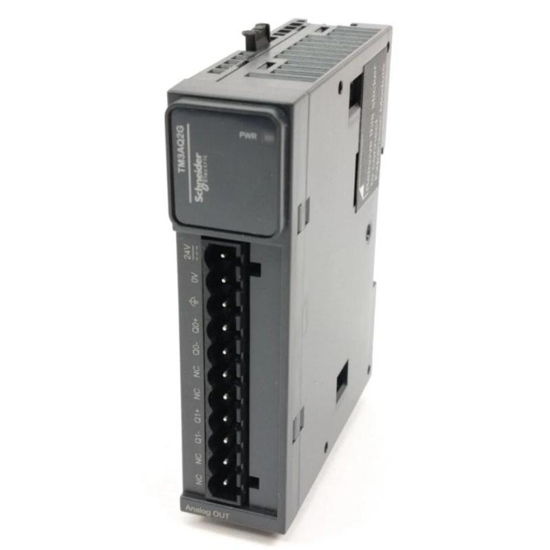
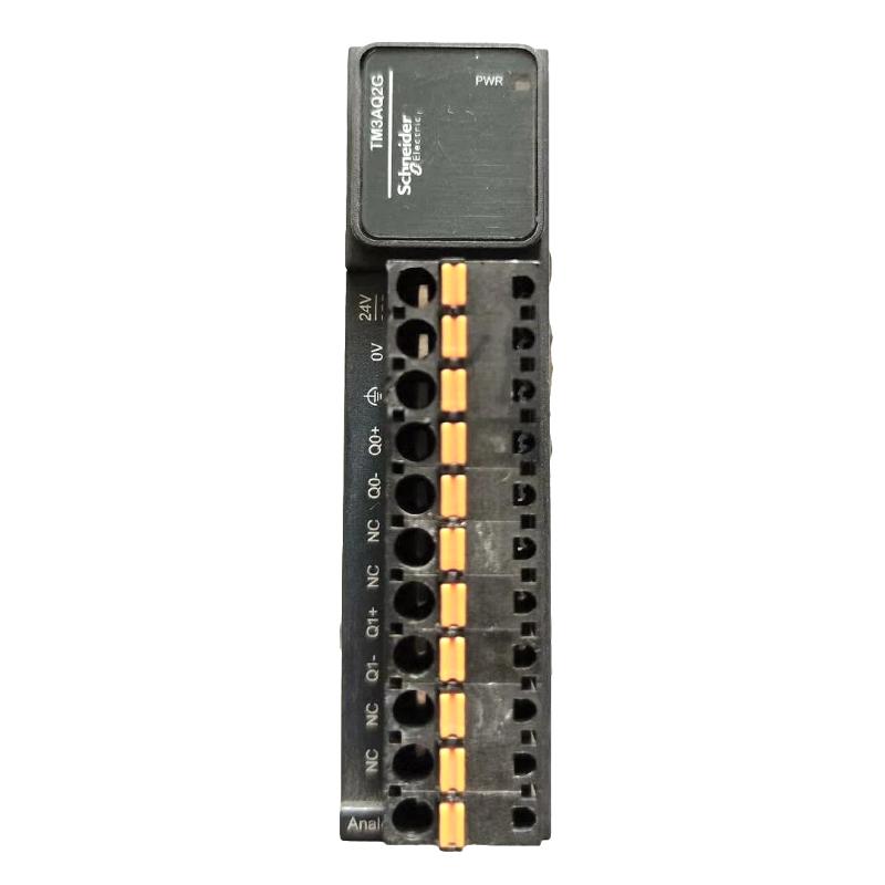
The Schneider TM3AQ2G is a two-channel analog output module in the Modicon TM3 expansion I/O family. It allows a compatible Modicon PLC to send continuously variable voltage or current reference signals to external equipment, making it suitable for applications that require more than simple digital ON/OFF control.
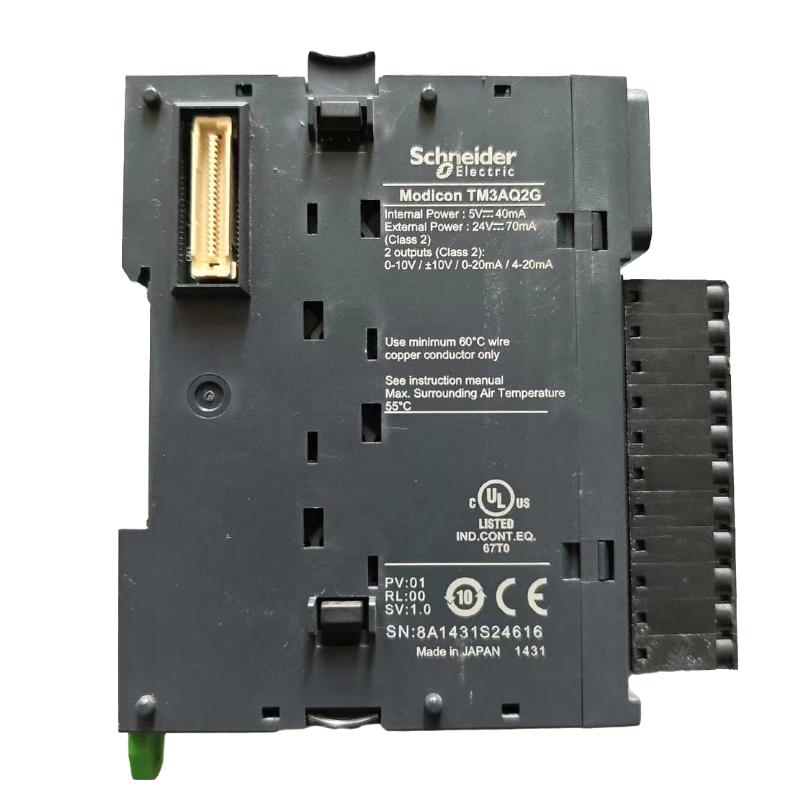
The module supports four standard output ranges: 0–10 V, -10–10 V, 0–20 mA, and 4–20 mA. These signals are commonly used as speed references for variable frequency drives, positioning commands for proportional actuators, and control references for process equipment.
In a pump control system, for example, the TM3AQ2G can generate an analog speed reference for a variable speed drive. The PLC calculates the required output according to the process conditions and sends the corresponding voltage or current signal through one of the module’s two output channels. The drive interprets this reference and adjusts motor speed accordingly.
The two-channel configuration is also useful in machinery where separate analog commands are required for two devices. A packaging machine might use one output to regulate conveyor speed and another to control a proportional valve, with both commands managed by the same PLC.
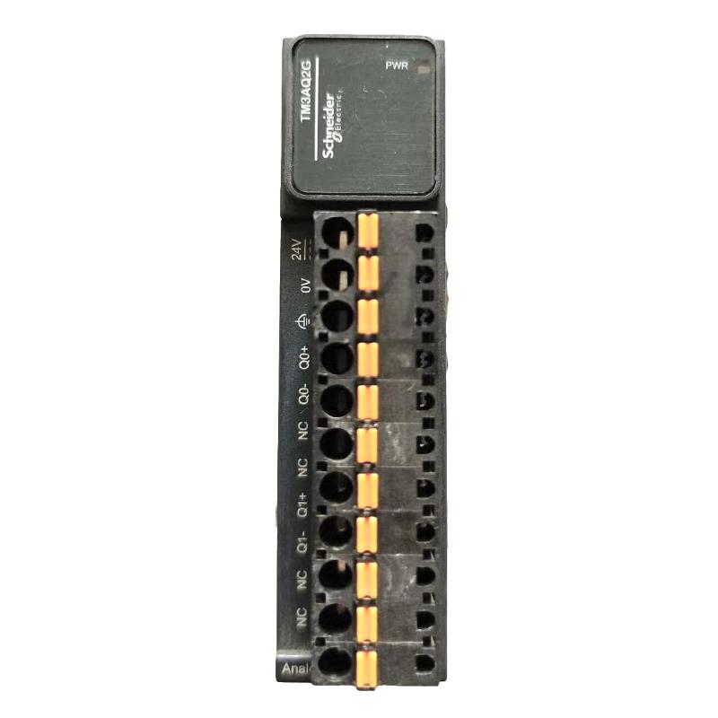
The TM3AQ2G uses removable spring terminal blocks with a 5.08 mm pitch. This connection arrangement distinguishes it from the TM3AQ2, which uses screw terminals. Both models provide two analog output channels, but the terminal type should be considered when selecting a replacement for an existing installation.
As part of the Modicon TM3 expansion system, the TM3AQ2G connects to compatible M221, M241, M251, and M262 controllers through the expansion bus. Its compact format makes it suitable for adding analog control outputs to an existing machine control cabinet.
Technical Specifications
| Parameter | Specification |
|---|---|
| Manufacturer | Schneider Electric |
| Model | TM3AQ2G |
| Product Family | Modicon TM3 |
| Product Type | Analog Output Module |
| Number of Analog Outputs | 2 |
| Analog Output Type | Voltage / Current |
| Voltage Output Range | 0–10 V / -10–10 V |
| Current Output Range | 0–20 mA / 4–20 mA |
| Analog Output Resolution | 12 bits / 11 bits + sign |
| Rated Supply Voltage | 24 V DC |
| Supply Voltage Range | 20.4–28.8 V DC |
| Voltage Output Load Impedance | ≥ 1 kΩ |
| Current Output Load Impedance | ≤ 300 Ω |
| Load Type | Resistive |
| Stabilisation Time | 1 ms |
| Conversion Time | 1 ms + 1 ms per channel + 1 controller cycle time |
| Absolute Accuracy Error | ±0.1% FS at 25°C / ±1% FS |
| Repeat Accuracy | ±0.4% FS |
| Non-Linearity | ±0.01% FS |
| Temperature Drift | ±0.006% FS/°C |
| Output Ripple | 20 mV maximum |
| Cross Talk | ≤ 1 LSB |
| Input Value of LSB | 2.44 mV (0–10 V) / 4.88 mV (-10–10 V) / 4.88 μA (0–20 mA) / 3.91 μA (4–20 mA) |
| Output Connection | Removable Spring Terminal Block |
| Terminal Pitch | 5.08 mm |
| Cable Requirement | Twisted Shielded Pair, Maximum 30 m |
| Local Signalling | 1 Green PWR LED |
| Protection Degree | IP20 |
| Compatible Controllers | Modicon M221 / M241 / M251 / M262 |
| Output-to-Internal Logic Insulation | 500 V AC |
| Output-to-Supply Insulation | 1500 V AC |
| Dimensions | 90 × 23.6 × 70 mm |
| Weight | 0.1 kg |
Product Features
- Two independent analog output channels.
- Supports both voltage and current output signals.
- Configurable 0–10 V and -10–10 V voltage ranges.
- Supports 0–20 mA and 4–20 mA current ranges.
- 12-bit resolution or 11 bits plus sign, depending on the selected output range.
- Removable spring terminal blocks for field connections.
- 24 V DC rated supply voltage.
- 1 ms output stabilisation time.
- Suitable for resistive output loads.
- Compatible with Modicon M221, M241, M251, and M262 controllers.
- Uses the Modicon TM3 expansion bus.
- Supports twisted shielded-pair output cables up to 30 m.
- IP20 protection for installation inside industrial control enclosures.
- Green PWR LED for local power status indication.
Working Principle
The TM3AQ2G converts digital output commands from the PLC into analog electrical signals that external devices can interpret as control references.
A typical signal path is:
PLC Control Program → TM3 Expansion Bus → TM3AQ2G → Analog Output Signal → Drive / Actuator
The PLC program determines the required output value according to machine conditions, operator settings, or process feedback. The TM3AQ2G receives the digital command through the TM3 expansion bus and converts it into the selected voltage or current signal.
For example, when controlling a variable speed drive through a 0–10 V reference, the PLC can send an output value corresponding to the required motor speed. A higher analog reference produces a higher speed command when the drive is configured to interpret the signal in that manner.
The same principle applies to current-loop control. A 4–20 mA output can be used to regulate a compatible proportional valve or another industrial device. The receiving equipment interprets the current according to its configured operating range.
Each output channel can be configured independently in EcoStruxure Machine Expert. Available settings include 0–10 V, -10–10 V, 0–20 mA, 4–20 mA, and an unused channel setting.
The output circuit must match the selected software configuration. For example, wiring a channel for voltage operation while configuring it for current output can damage the analog circuit. The connected load must also remain within the specified impedance range: at least 1 kΩ for voltage outputs and no more than 300 Ω for current outputs.
The module’s conversion time includes the channel conversion period and the controller cycle time. This should be considered when the application requires frequent updates to drive references or proportional control commands.
Role in a Modicon TM3 PLC Control Architecture
The TM3AQ2G occupies the analog command output position within a Modicon TM3 expansion I/O arrangement. While analog input modules collect information from field instruments, the TM3AQ2G sends continuously variable commands from the PLC to external equipment.
A typical control arrangement is:
PLC → TM3 Expansion Bus → TM3AQ2G → Analog Reference Signal → Variable Speed Drive / Proportional Actuator
| System Element | Function |
|---|---|
| TM3AQ2G | Generates two configurable analog output signals |
| Modicon M221 | Executes machine-control logic and output commands |
| Modicon M241 | Handles machine automation and motion-related control |
| Modicon M251 | Supports connected machine-control architectures |
| Modicon M262 | Handles advanced machine-control applications |
| TM3 Expansion Bus | Transfers output data between the PLC and expansion module |
| EcoStruxure Machine Expert | Configures output channels and PLC application logic |
| Variable Speed Drive | Receives analog speed or frequency references |
| Proportional Control Valve | Uses analog commands to regulate valve position or flow |
| Servo or Positioning Equipment | Receives compatible analog reference signals |
| 24 V DC Power Supply | Supplies the required external module power |
In a pump application, the PLC can calculate the required speed reference from pressure or flow measurements acquired through separate analog input modules. The TM3AQ2G then converts the command into a 0–10 V or 4–20 mA signal for the drive.
The two outputs can also serve separate control functions. For example, one channel can regulate motor speed while the other adjusts a proportional valve, allowing two analog-controlled devices to operate within the same machine architecture.
Industrial Applications
| Application | Typical Use |
|---|---|
| Pump Control Systems | Sending variable speed references to pump drives |
| HVAC Systems | Controlling fan speed and proportional valve operation |
| Water Treatment | Regulating pumps and flow-control equipment |
| Compressor Control Systems | Sending analog reference commands to compatible drive systems |
| Packaging Machinery | Adjusting conveyor speed and proportional machine settings |
| Chemical Processing | Controlling proportional valves and process equipment |
| Food and Beverage Production | Regulating flow and other continuously controlled process variables |
| Material Handling | Sending analog speed references to conveyor drives |
| Manufacturing Lines | Controlling external devices through PLC-generated analog signals |
| Industrial Process Control | Providing voltage or current references to compatible actuators and drives |
Installation and Maintenance
- Verify the Module Reference: Confirm that the required module is TM3AQ2G. The TM3AQ2 uses screw terminals, whereas the TM3AQ2G uses spring terminal connections.
- Check Controller Compatibility: Verify that the installed Modicon M221, M241, M251, or M262 controller supports the planned TM3 expansion configuration.
- Identify Output Devices: Determine which external equipment will receive the two analog output signals and check their required signal types.
- Confirm Output Ranges: Identify whether each connected device requires 0–10 V, -10–10 V, 0–20 mA, or 4–20 mA operation.
- Verify the Power Supply: Check that the external supply remains within the specified 20.4–28.8 V DC range.
- Inspect Spring Terminals: Make sure conductors are correctly inserted and securely held by the removable spring terminal blocks.
- Use Suitable Signal Cables: Use twisted shielded-pair cables for analog output circuits and keep cable length within the specified 30 m limit.
- Check Load Impedance: Confirm that voltage output loads are at least 1 kΩ and current output loads do not exceed 300 Ω.
- Configure Each Output: Set the appropriate output mode in EcoStruxure Machine Expert and ensure that the software settings match the physical wiring.
- Test Output Signals: Measure the actual voltage or current at the terminals and compare it with the command value generated by the PLC.
- Check Connected Equipment: If the receiving drive or actuator does not respond correctly, inspect the signal wiring, input configuration, load impedance, and external power supply.
- Document Output Assignments: Record the connected devices, selected signal ranges, and PLC output addresses to simplify future troubleshooting and replacement.
Related Components
| Component | Function |
|---|---|
| TM3AQ2 | Two-channel analog output module with screw terminals |
| TM3AQ4 | Four-channel analog output module with screw terminals |
| TM3AQ4G | Four-channel analog output module with spring terminals |
| TM3AM6G | Four analog inputs and two analog outputs with spring terminals |
| TM3AI4 | Four-channel analog input module |
| TM3AI8 | Eight-channel analog input module |
| Modicon M221 | PLC controller supporting TM3 expansion I/O |
| Modicon M241 | Machine controller with TM3 expansion capability |
| 24 V DC Power Supply | Supplies external module power |
| Variable Speed Drive | Receives analog speed reference commands |
| Proportional Control Valve | Regulates flow or pressure through analog control signals |
Recommended Related Models
| Model | Product Type | Typical Application |
|---|---|---|
| Schneider TM3AQ2 | Analog Output Module | Two-channel analog output with screw terminals |
| Schneider TM3AQ4 | Analog Output Module | Four-channel voltage and current output applications |
| Schneider TM3AQ4G | Analog Output Module | Four-channel analog output with spring terminals |
| Schneider TM3AM6G | Analog Input/Output Module | Combined process measurement and analog command generation |
| Schneider TM3AM6 | Analog Input/Output Module | Mixed analog I/O applications with screw terminals |
| Schneider TM3TM3G | Temperature and Analog Input/Output Module | Temperature acquisition and analog output control |
Key Advantages
- Two analog output channels in a compact TM3 expansion module.
- Supports standard industrial voltage and current reference signals.
- Independent configuration for different output requirements.
- 12-bit output resolution or 11 bits plus sign.
- Spring terminal connections simplify field wiring.
- Compatible with four Modicon PLC controller families.
- Suitable for variable speed drives and proportional control devices.
- Adds analog command capability without requiring a separate controller.
Technical FAQs
Can the TM3AQ2G control two variable speed drives independently?
Yes. The module has two analog output channels, allowing separate reference signals to be sent to two compatible drives. Each drive must be configured to accept the corresponding voltage or current input, and the PLC application must generate the appropriate command for each output.
What is the maximum load impedance supported by the TM3AQ2G?
The supported load impedance depends on the selected output type. Voltage outputs require a minimum load impedance of 1 kΩ, while current outputs support a maximum load impedance of 300 Ω. These limits should be checked against the receiving equipment before connecting the module.
Does the TM3AQ2G support 4–20 mA control signals?
Yes. The module supports both 0–20 mA and 4–20 mA current outputs. The selected range must match the receiving device’s analog input configuration. This is particularly relevant when connecting the module to process controllers, proportional valves, and drives that use current-loop references.
Why is the analog output different from the value commanded by the PLC?
Several factors can affect the measured output, including incorrect channel configuration, wiring errors, load impedance, external supply conditions, and the scaling used in the PLC application. Check the selected output mode first, then measure the terminal signal under the actual connected load. Also verify that the receiving device uses the same signal range as the TM3AQ2G output.