

ProductPRODUCT
Featured products
Contact Us
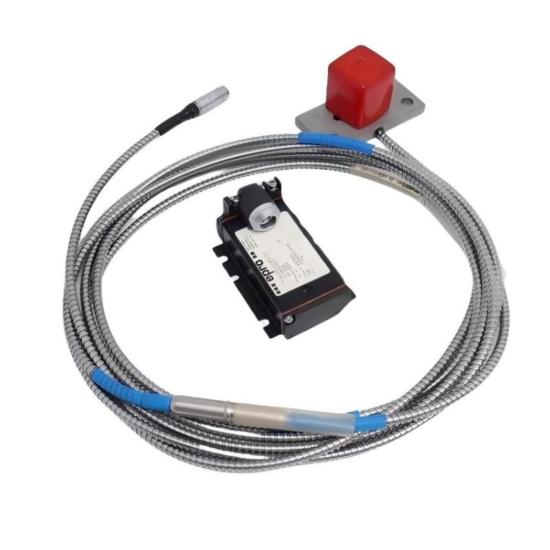
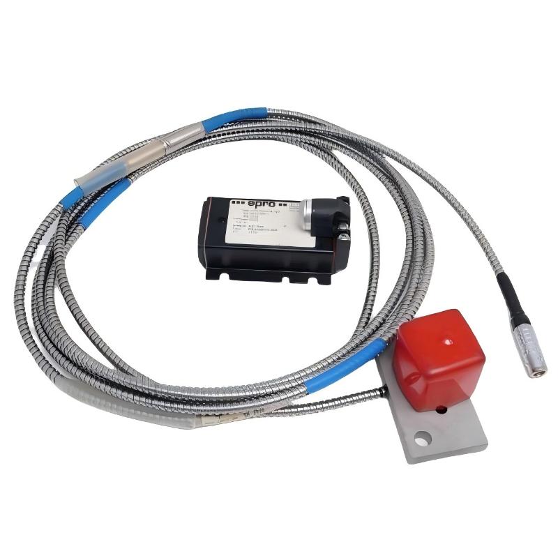
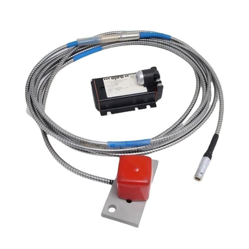
- Epro
- PR6426/000-030+CON021
- 32 mm Eddy Current Sensor + Eddy Current Signal Converter
- Germany
- 32 mm
- 0.92 kg
- Xiamen, China
- New & In Stock
- T/T, PayPal, Western Union
- 1 Year
- 1-3 Working Days
- DHL, UPS, TNT, FedEx and EMS.
- 24-Hour Service
- COO
- 6
Our advantage

Global Logistics
We have a 10-year logistics and express cooperation agreement, so our products can be shipped to any place in the world.

Brand new and original
Our products are imported in bulk from the place of origin. Because of the cooperative relationship, our products are all original and 100% new.

24-hour service
We provide 7*24 hours service to our customers. We will be there whenever you need us.

Price advantage
All our products are priced very favorably because we have our own warehouse and supply.
| Company Information | |||
| [email protected] | |||
| Mobile | +8615980777398 | ||
| +8615980777398 | |||
| 15980777398 |
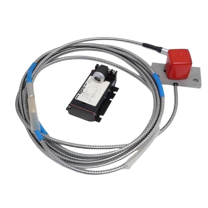
Product Overview
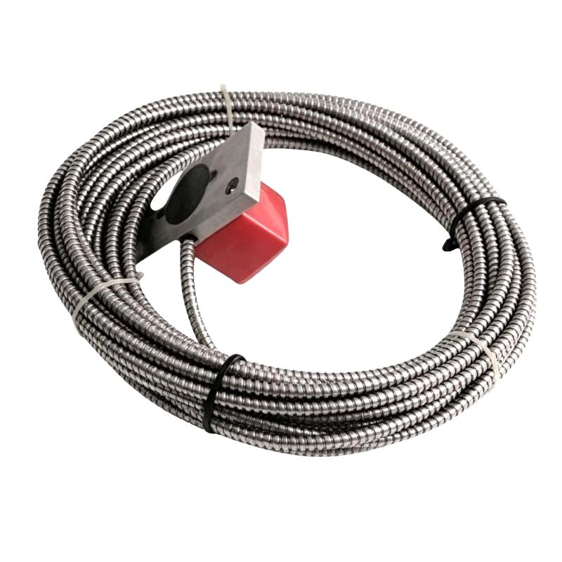
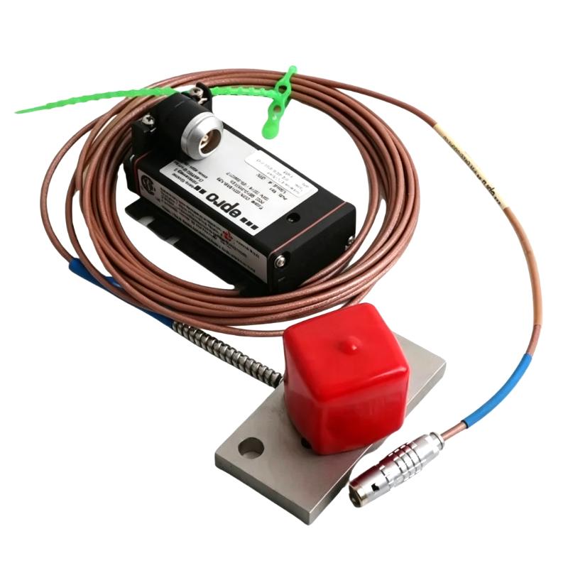
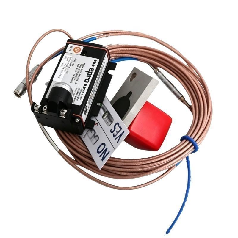
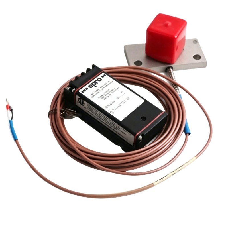
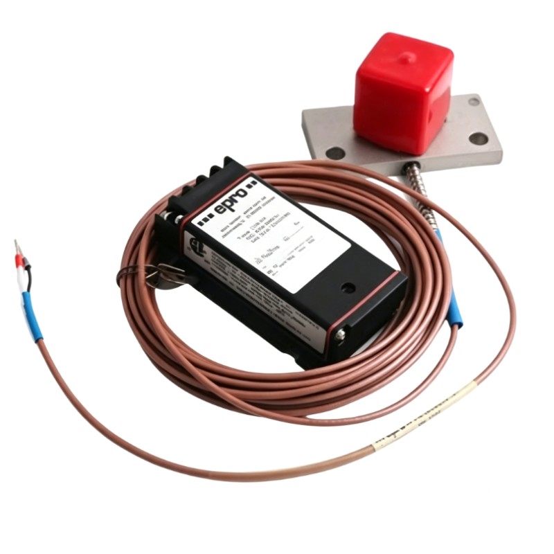
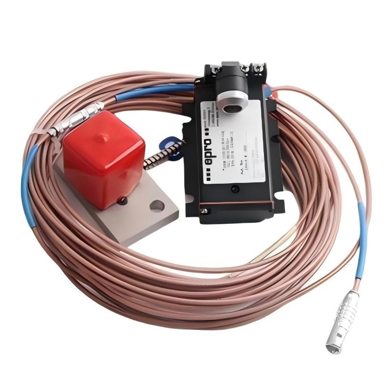
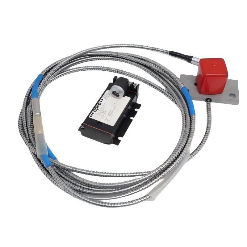
The Epro PR6426/000-030+CON021 is a combined eddy current measurement assembly consisting of a PR6426 32 mm eddy current sensor and a CON021 signal converter. The combination is used for non-contact measurement of shaft displacement, position, eccentricity, and movement in critical rotating machinery.
Unlike a standalone proximity sensor, this combination includes the signal conversion stage required to process the probe’s electrical response. The PR6426/000-030 detects changes in the distance between the sensor head and a conductive metallic target, while the CON021 processes the resulting signal and generates an output suitable for connection to a machinery monitoring system.
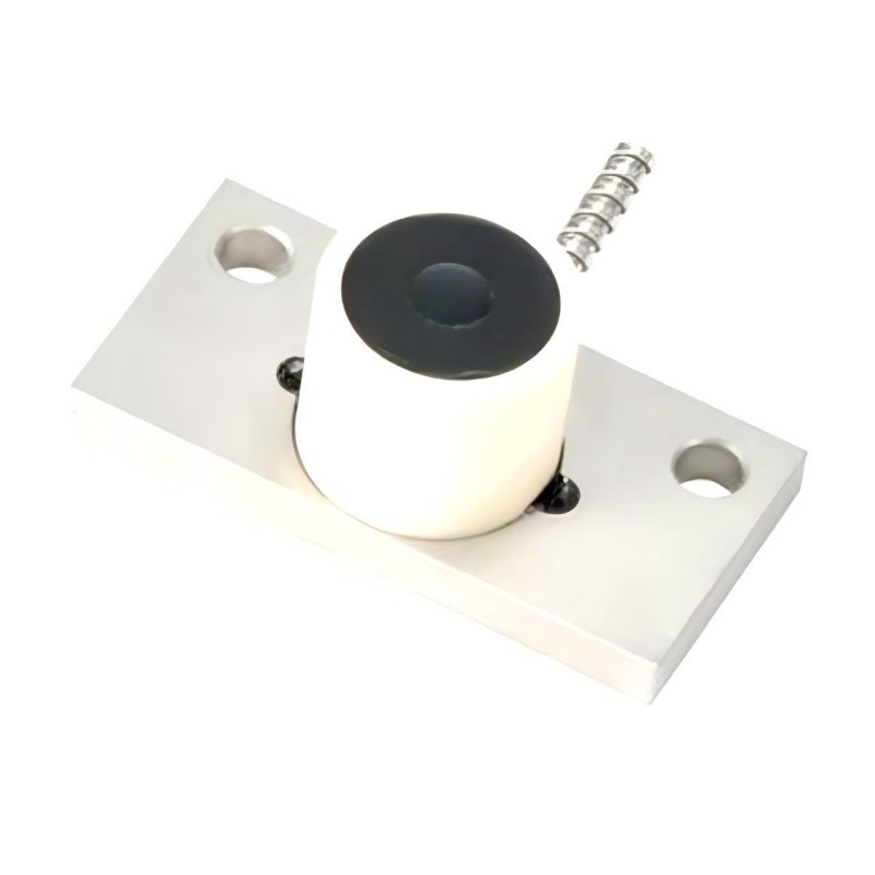
The PR6426/000-030 uses a non-threaded sensor sleeve and an 80 × 40 mm mounting plate. Its 32 mm sensing head is intended for large-shaft measurement applications, including steam turbines, gas turbines, centrifugal compressors, pumps, and industrial fans. The mounting plate allows the sensor to be fixed to the machine structure and positioned toward the shaft or measuring collar.
This particular sensor configuration includes an 8 m non-armored PTFE cable with an adapter plug and LEMO connector. The extended cable length is useful when the probe is installed inside a turbine or compressor housing while the CON021 converter is mounted at a more accessible location.
The CON021 is a panel-mounted eddy current signal converter. It receives the sensor signal through its self-locking LEMO connection and processes the measurement before delivering an output through screw terminals. The converter supports displacement measurement and can also be used in appropriate monitoring arrangements for shaft position, eccentricity, and speed/key-related measurements.
The sensor has a nominal sensitivity of 2 V/mm and a static measuring range of ±4.0 mm. Its nominal center air gap is approximately 5.5 mm. When paired with the appropriate standard-range CON021 configuration, the measurement chain can be used to monitor changes in shaft position without physical contact.
In a centrifugal compressor, for example, the PR6426 probe can be mounted near the rotor to detect radial shaft movement. The 8 m cable carries the sensor signal to the CON021 converter, which processes the electrical response and supplies the corresponding displacement output to the monitoring equipment. This arrangement allows the measurement point and conversion electronics to be installed at different physical locations.
The combination is particularly relevant when replacing an existing PR6426 measurement assembly. Matching the sensor model, cable termination, converter measuring range, electrical supply, and output configuration is necessary to maintain compatibility with the existing monitoring system.
Technical Specifications
PR6426/000-030 Eddy Current Sensor
| Parameter | Specification |
|---|---|
| Manufacturer | Epro |
| Model | PR6426/000-030 |
| Product Type | 32 mm Eddy Current Sensor |
| Measuring Principle | Non-Contact Eddy Current |
| Sensor Head Diameter | 32 mm |
| Static Measuring Range | ±4.0 mm |
| Nominal Sensitivity | 2 V/mm (50.8 mV/mil) |
| Maximum Linearity Error | ±1.5% |
| Nominal Center Air Gap | Approximately 5.5 mm |
| Long-Term Drift | < 0.3% |
| Standard Target Material | Ferromagnetic Steel (42CrMo4) |
| Minimum Shaft Diameter | ≥ 200 mm |
| Operating Temperature Range | -35 to 175°C |
| Short-Term Temperature Excursion | 200°C for Less Than 4 Hours |
| Maximum Cable Temperature | 200°C |
| Sensor Sleeve Material | Stainless Steel |
| Cable Material | PTFE |
| Cable Diameter | 2.8 mm |
| Mounting Configuration | 80 × 40 mm Mounting Plate |
| Sleeve Thread | No Thread |
| Cable Protection | Non-Armored |
| Adapter Plug | Included |
| Total Cable Length | 8 m |
| Cable End | LEMO Connector |
| Minimum Cable Bending Radius | 25 mm |
| Sensor Head Pressure Resistance | 6,500 hPa (94 psi) |
| Shock and Vibration Resistance | 5g at 60 Hz and 25°C |
CON021 Eddy Current Signal Converter
| Parameter | Specification |
|---|---|
| Manufacturer | Epro |
| Model | CON021 |
| Product Type | Eddy Current Signal Converter |
| Compatible Sensor Family | PR6422, PR6423, PR6424, PR6425, PR6426 |
| PR6426 Standard Measuring Range | 4.0 mm |
| Linearity Error for PR6426 Standard Range | ≤ ±1.5% |
| Frequency Range (-3 dB) | 0–20,000 Hz |
| Rise Time | < 15 μs |
| Operating Temperature Range | -30 to 100°C |
| Supply Voltage Range | -23 to -32 V DC |
| Alternative Supply Configuration | -21 to -32 V DC |
| Output Voltage Range | -4 to -20 V / -2 to -18 V |
| Protection Class | IP20 |
| Housing Material | LMgSi 0.5 F22 |
| Mounting Type | Panel Mount |
| Mounting Arrangement | 4 × M5 Screws |
| Sensor Connection | Self-Locking LEMO Plug |
| Supply / Output Connection | Screw Terminals |
| Maximum Terminal Wire Cross-Section | 1.5 mm² |
| Shock and Vibration Resistance | 5g at 60 Hz and 25°C |
| Converter Weight | Approximately 120 g |
Product Features
- Complete measurement arrangement combining a PR6426 sensor and CON021 signal converter.
- 32 mm eddy current sensing head for large rotating machinery.
- Non-contact shaft displacement measurement.
- Static sensor measuring range of ±4.0 mm.
- Nominal sensitivity of 2 V/mm.
- Approximately 5.5 mm nominal center air gap.
- 80 × 40 mm sensor mounting plate.
- Non-threaded stainless-steel sensor sleeve.
- 8 m non-armored PTFE cable.
- LEMO connector with adapter plug.
- Panel-mounted CON021 signal converter.
- Self-locking LEMO sensor input connection.
- Screw-terminal connections for converter supply and output.
- Frequency response up to 20 kHz (-3 dB).
- Converter rise time below 15 μs.
- Selectable voltage output arrangements.
- Compatible with supported PR6426 standard-range measurement configurations.
Working Principle
The PR6426/000-030 and CON021 work together as a two-stage measurement system. The sensor detects changes in the distance between the probe face and a metallic target, while the converter processes the sensor response into a usable electrical measurement signal.
The PR6426 contains a sensing coil that generates an alternating electromagnetic field. When the probe is positioned near a conductive shaft, eddy currents are induced in the target surface. These currents influence the electrical characteristics of the sensing coil.
When the shaft moves, the distance between the sensing head and target changes. This affects the electromagnetic interaction and produces a corresponding change in the sensor signal.
The measurement process follows this sequence:
Rotating Shaft → PR6426/000-030 → 8 m Sensor Cable → CON021 → Voltage Output → Machinery Monitoring System
The CON021 receives the sensor signal through its self-locking LEMO connection. Its internal signal processing circuitry converts the probe response into a displacement-related output. The processed signal is then available through the converter’s screw terminals for connection to compatible monitoring equipment.
For example, when the assembly is installed on a centrifugal compressor, the PR6426 probe can monitor radial movement of the rotor. If the shaft moves closer to the sensor, the measured air gap decreases. Movement away from the sensor increases the gap. The converter processes these changes so that the monitoring system can evaluate the shaft’s displacement during operation.
The PR6426 has a nominal sensitivity of 2 V/mm and a static measuring range of ±4.0 mm. The initial air gap is approximately 5.5 mm. Correct adjustment is necessary to maintain the intended measuring range and prevent the sensor from operating outside its linear region.
The standard target material is ferromagnetic 42CrMo4 steel. Differences in shaft material can affect the electromagnetic response, so the actual target material must be considered when configuring the complete measurement chain.
The CON021 also supports a frequency range of 0 to 20 kHz and a rise time below 15 μs. These characteristics allow the measurement system to handle both relatively slow shaft position changes and faster dynamic movement associated with rotating machinery.
Role in a Machinery Protection and Condition Monitoring Architecture
The PR6426/000-030+CON021 assembly provides both the physical sensing element and the signal conversion stage within a machinery monitoring arrangement.
The sensor is installed near the rotating shaft, while the converter can be mounted separately in a suitable panel or equipment enclosure. This separation is useful in turbine and compressor installations where the measuring point is located inside the machine and the monitoring electronics are installed in a control cabinet.
A typical measurement architecture is:
Rotating Shaft → PR6426/000-030 → 8 m Cable → CON021 → Monitoring Input → Machinery Protection System
| System Element | Function |
|---|---|
| PR6426/000-030 | Detects radial or axial shaft displacement |
| 8 m Sensor Cable | Transfers the probe signal to the converter |
| LEMO Connection | Provides the sensor input connection to CON021 |
| CON021 | Processes the eddy current sensor signal and generates the measurement output |
| Screw Terminal Interface | Provides electrical connections for converter supply and output |
| AMS 3000 Series | Machinery monitoring equipment supporting compatible sensor arrangements |
| AMS 6500 | Machinery protection and condition monitoring platform |
| Machinery Monitoring Rack | Collects and evaluates shaft measurement signals |
| DCS / SCADA | Displays machinery operating conditions and measurement information |
In a turbine installation, multiple sensor assemblies may be used to monitor different shaft measurement points. Radial displacement sensors can be positioned around the rotor, while an appropriately arranged sensor can measure axial shaft movement.
Each PR6426 probe supplies its measurement response to the associated converter. The CON021 processes the signal before it reaches the monitoring system, where displacement trends and operating conditions can be evaluated.
The monitoring equipment can use the processed measurements for alarm generation and machinery protection functions. The actual alarm thresholds and shutdown logic are configured in the connected protection system rather than in the sensor itself.
The converter’s output range and supply arrangement must match the receiving equipment. This is particularly important when replacing an existing assembly, because the voltage output configuration and terminal wiring may differ between installations.
Industrial Applications
| Application | Typical Use |
|---|---|
| Steam Turbines | Monitoring rotor axial displacement, radial shaft movement, and eccentricity |
| Gas Turbines | Measuring shaft position and dynamic rotor movement |
| Hydro Turbines | Monitoring displacement in large rotating shaft assemblies |
| Centrifugal Compressors | Detecting radial shaft movement and changes in rotor position |
| Industrial Pumps | Monitoring shaft displacement and mechanical operating conditions |
| Large Industrial Fans | Measuring shaft movement and eccentricity |
| Power Generation | Providing displacement measurements for turbine protection systems |
| Petrochemical Plants | Monitoring critical compressors and process rotating machinery |
| Refinery Equipment | Measuring shaft position in large rotating equipment |
| Industrial Machinery Protection | Supplying processed displacement signals to monitoring and protection systems |
Installation and Maintenance
- Verify the Complete Assembly: Confirm that the supplied equipment includes the PR6426/000-030 sensor and compatible CON021 converter. Check the 8 m cable length, LEMO connection, mounting plate, and converter configuration.
- Inspect the Sensor Mounting Plate: Check the 80 × 40 mm mounting plate and fixing points for damage, deformation, or contamination before installation.
- Select the Measuring Position: Determine whether the probe will measure radial or axial displacement. Position the sensing face toward the intended shaft measuring surface.
- Maintain the Required Clearance: Keep the specified measuring area around the sensor head free from nearby ferrous materials that could interfere with the electromagnetic field.
- Inspect the Target Surface: Check the shaft measuring track for corrosion, scratches, deposits, and excessive surface irregularities.
- Confirm Target Material: Verify that the shaft material matches the standard 42CrMo4 reference material or that the complete measuring chain has been adjusted for the actual target material.
- Adjust the Initial Air Gap: Position the sensor according to the intended measuring configuration. The nominal center air gap is approximately 5.5 mm. Confirm the final position using the converter output.
- Secure the Sensor Mounting: Tighten the mounting hardware and ensure that the sensor plate cannot shift under operating vibration or thermal movement.
- Route the 8 m Cable: Keep the non-armored cable away from rotating parts, sharp edges, excessive tension, and unsuitable high-temperature surfaces. Maintain a minimum bending radius of 25 mm.
- Connect the CON021: Insert the sensor’s LEMO connector into the converter’s self-locking sensor input. Check that the connector is properly engaged and that the contacts are clean.
- Check Power and Output Wiring: Connect the CON021 supply and output terminals according to the selected voltage configuration. Verify the required negative DC supply range and the receiving equipment’s input requirements before energizing the system.
- Verify the Complete Measurement Chain: Check the sensor response, converter output, initial air gap, and monitoring-system indication. Record the sensor position, cable route, converter settings, output configuration, and installation details for future maintenance.
Compatible System Components
| Component | Function |
|---|---|
| Epro PR6426/000-030 | 32 mm eddy current sensor with 8 m LEMO cable |
| Epro CON021 | Panel-mounted eddy current signal converter |
| Epro CON011 | Alternative signal conversion equipment for supported PR642x sensors |
| Epro CON041 | Eddy current signal converter for compatible measurement arrangements |
| Epro AMS 3000 Series | Machinery monitoring platform supporting compatible sensor inputs |
| Epro AMS 6500 | Machinery protection and condition monitoring equipment |
| LEMO Connection | Connects the PR6426 sensor cable to the CON021 |
| Screw Terminal Interface | Provides converter power and measurement output connections |
| Machinery Monitoring Rack | Collects and processes displacement measurement signals |
| DCS / SCADA System | Displays measurement values and machinery operating conditions |
Recommended Related Models
| Model | Product Type | Typical Application |
|---|---|---|
| Epro PR6426/000-020 | 32 mm Eddy Current Sensor | 6 m LEMO cable configuration |
| Epro PR6426/000-030 | 32 mm Eddy Current Sensor | 8 m LEMO cable configuration |
| Epro PR6426/000-040 | 32 mm Eddy Current Sensor | 10 m LEMO cable configuration |
| Epro PR6426/000-031 | 32 mm Eddy Current Sensor | 8 m open-ended cable configuration |
| Epro CON021/916-120 | Eddy Current Signal Converter | PR6426 extended-range measurement |
| Epro CON021/916-160 | Eddy Current Signal Converter | PR6426 extended-range measurement |
Key Advantages
- Combines shaft sensing and signal conversion in one measurement assembly.
- 32 mm probe for large rotating machinery.
- Non-contact radial and axial displacement measurement.
- 2 V/mm nominal sensor sensitivity.
- ±4.0 mm static sensor measuring range.
- 8 m cable for installations with greater distance between the probe and converter.
- LEMO connection for the sensor input.
- Panel-mounted CON021 with screw-terminal supply and output connections.
- Converter frequency response up to 20 kHz.
- Suitable for turbine, compressor, pump, and fan monitoring applications.
Technical FAQs
What is the difference between the PR6426/000-030 and the complete PR6426/000-030+CON021 assembly?
The PR6426/000-030 is the sensing probe with its cable and connector configuration. The complete PR6426/000-030+CON021 assembly also includes the CON021 signal converter. The converter processes the probe signal and provides an electrical output for compatible machinery monitoring equipment. When ordering a replacement, confirm whether the application requires only the probe or the complete sensor and converter combination.
What measuring range does the CON021 support with a PR6426 sensor?
The standard CON021 configuration supports a 4.0 mm measuring range for the PR6426 sensor family, with a linearity error of no more than ±1.5%. The PR6426 sensor itself has a static measuring range of ±4.0 mm. Extended-range CON021 versions, such as the /916-120 and /916-160, have different measurement ranges and should not be confused with the standard CON021 configuration.
How is the CON021 connected to the machinery monitoring system?
The PR6426 sensor connects to the CON021 through its self-locking LEMO input. The converter’s power supply and output are connected through screw terminals. Depending on the selected configuration, the output is either -4 to -20 V or -2 to -18 V. The receiving monitoring equipment must support the selected output arrangement and the required negative DC supply configuration.
Can the 8 m PR6426/000-030 cable be replaced with a shorter cable?
The cable length is part of the specified sensor configuration and should be maintained when replacing the complete measuring assembly. Changing the cable arrangement may affect the electrical characteristics and calibration of the measurement chain. Any cable modification should be evaluated against the sensor and converter requirements, followed by verification of the complete measurement response.