

ProductPRODUCT
Featured products
Contact Us
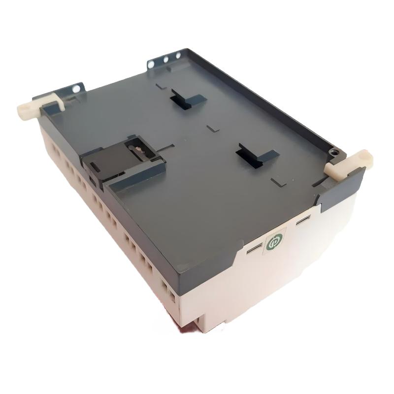
- Schneider
- SR2A201BD
- Zelio Logic Compact Smart Relay
- France
- 124.6 x 90 x 59.5 mm
- 0.38 kg
- Xiamen, China
- New & In Stock
- T/T, PayPal, Western Union
- 1 Year
- 1-3 Working Days
- DHL, UPS, TNT, FedEx and EMS.
- 24-Hour Service
- COO
- 12
Our advantage

Global Logistics
We have a 10-year logistics and express cooperation agreement, so our products can be shipped to any place in the world.

Brand new and original
Our products are imported in bulk from the place of origin. Because of the cooperative relationship, our products are all original and 100% new.

24-hour service
We provide 7*24 hours service to our customers. We will be there whenever you need us.

Price advantage
All our products are priced very favorably because we have our own warehouse and supply.
| Company Information | |||
| [email protected] | |||
| Mobile | +8615980777398 | ||
| +8615980777398 | |||
| 15980777398 |
Product Overview
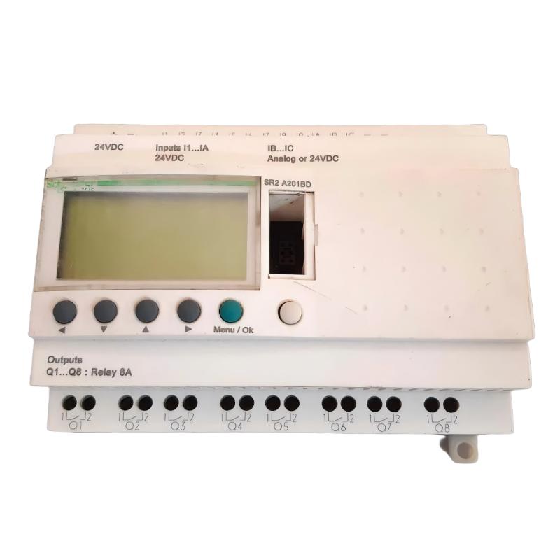
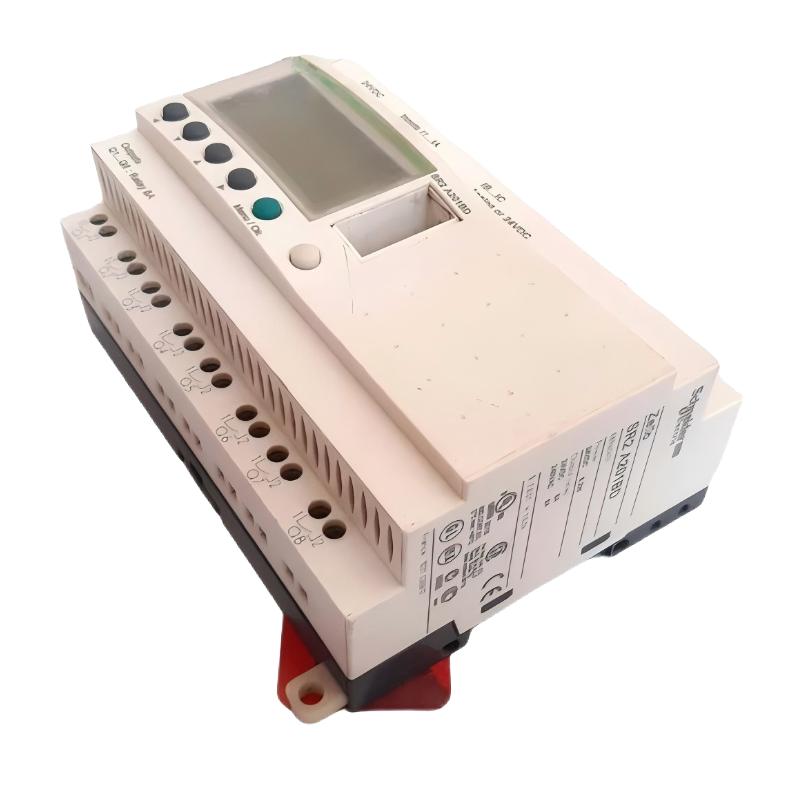
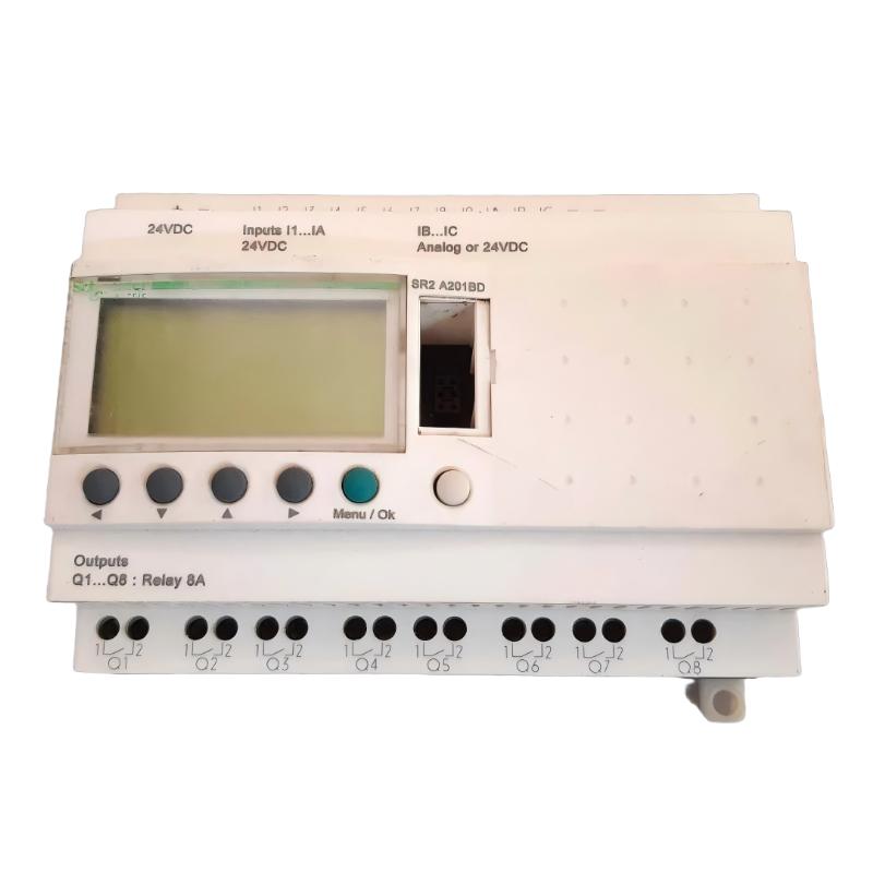
The Schneider Electric SR2A201BD Zelio Logic Compact Smart Relay is a programmable control device designed for small-scale automation applications in industrial equipment, building systems, and commercial installations. Belonging to the Zelio Logic SR2 range, it combines programmable logic functions, integrated input and output interfaces, and a local display in a compact housing.
Unlike a conventional control relay that performs a single switching function, the SR2A201BD can execute a user-defined control program. It processes input signals from sensors, switches, and other field devices, evaluates programmed logic, and controls connected equipment through its relay outputs.
The SR2A201BD provides 20 I/O points, consisting of 12 digital inputs and 8 relay outputs. Two of the input channels can also be configured for analog measurement, supporting signals within the specified 0–10 V or 0–24 V ranges. This combination allows the smart relay to handle a variety of basic control tasks without requiring a separate PLC and multiple individual logic relays.
The unit operates from a 24 V DC supply and includes an integrated LCD display for local monitoring and navigation. It supports ladder programming and function block diagram programming, allowing users to develop control sequences according to their application requirements. The model does not include a real-time clock, so applications that depend on scheduled operations must use an appropriate external control arrangement or a different model with clock functionality.
With its compact design, DIN-rail mounting capability, and screw-clamp connections, the SR2A201BD is suitable for control panels where installation space and straightforward wiring are important considerations.
Technical Specifications
| Parameter | Specification |
|---|---|
| Brand | Schneider Electric |
| Product Series | Zelio Logic SR2 |
| Model | SR2A201BD |
| Product Type | Compact Smart Relay |
| Rated Supply Voltage | 24 V DC |
| Supply Voltage Range | 19.2–30 V DC |
| Total I/O | 20 points |
| Digital Inputs | 12 |
| Analog Inputs | 2 configurable input channels |
| Relay Outputs | 8 |
| Analog Input Range | 0–10 V / 0–24 V |
| Analog Input Resolution | 8 bits |
| Maximum Supply Current | 100 mA without extension |
| Power Dissipation | 6 W without extension |
| Programming Languages | Ladder Logic and Function Block Diagram |
| Ladder Programming Capacity | Up to 240 control lines |
| Operating Cycle Time | 6–90 ms |
| Local Display | Integrated LCD |
| Real-Time Clock | Not included |
| Program Backup | Up to 10 years at 25°C |
| Input Compatibility | 3-wire PNP proximity sensors |
| Protection | Reverse-polarity protection |
| Mounting | 35 mm DIN rail or screw fixing |
| Protection Rating | IP20 / IP40, depending on installation conditions |
| Dimensions | 124.6 × 90 × 59.5 mm |
| Weight | 0.38 kg |
Specifications should be checked against the product revision and applicable installation documentation before system design or replacement.
Function and Working Principle
The SR2A201BD operates as a compact programmable controller. It receives electrical signals from connected devices, processes them through a stored program, and changes the state of its output relays according to the programmed conditions.
1. Digital Signal Acquisition
The smart relay has 12 digital input channels designed to receive signals from switches, push buttons, limit switches, and compatible proximity sensors.
These inputs allow the controller to detect operating conditions such as:
- Machine start and stop commands.
- Door and safety-interlock status.
- Equipment position.
- Product detection.
- Motor overload contact status.
- Tank level switch signals.
The controller evaluates the input states during its program execution cycle. Based on the programmed logic, it determines which output actions should be activated.
2. Analog Signal Processing
Two input channels can be configured for analog measurement. The supported input ranges include 0–10 V and 0–24 V, with an 8-bit resolution.
Analog signals can represent process variables such as temperature-transmitter output, pressure, liquid level, or other voltage-based measurements. The smart relay can use these values in programmed logic to determine when an output should change state.
For example, a control program may compare an analog input with a predefined threshold and activate a relay output when the measured value exceeds that threshold.
The analog input accuracy and resolution should be considered when selecting the device for measurement-sensitive applications. It is intended for compact automation tasks rather than high-precision process instrumentation.
3. Program Execution
The SR2A201BD executes a user-defined control program using its internal processing system. It supports ladder logic and function block diagram programming.
Ladder logic represents control conditions through contacts, coils, timers, counters, and related elements. This format is familiar to many industrial maintenance technicians and electrical engineers.
Function block diagram programming provides another way to organize control operations through interconnected functional elements.
The controller’s cycle time is specified as 6–90 ms, depending on the program and execution conditions.
4. Relay Output Switching
The device provides eight relay outputs. These outputs can switch compatible electrical loads, including contactor coils, indicator lamps, small control devices, and auxiliary relays.
A relay output provides electrical switching through mechanical contacts. The load voltage, current, switching frequency, and inductive characteristics must remain within the specified contact ratings.
For larger motors, heaters, or high-current equipment, the smart relay should generally control an appropriately rated contactor or interface device rather than switch the power load directly.
5. Local Display and Program Monitoring
The integrated LCD display provides a local interface for viewing operating information and navigating the device’s available functions.
This is useful during commissioning and maintenance because technicians can inspect controller information without relying entirely on an external operator panel.
The SR2A201BD does not include a real-time clock. Its control program therefore cannot rely on an internal clock for time-of-day scheduling.
Role in Industrial Automation Systems
The SR2A201BD is intended for compact automation systems where a dedicated small controller can manage local equipment without the complexity of a larger PLC architecture.
Standalone Machine Control
The smart relay can manage basic machine sequences involving switches, sensors, timers, counters, and output devices.
For example, it can control a small material-feeding machine by detecting product presence, starting a motor through a contactor, and stopping the process when a predefined condition is reached.
Electrical Panel Control
The device can be installed inside a control cabinet to coordinate auxiliary electrical functions. Typical examples include ventilation control, lighting sequences, pump alternation logic, and equipment status indication.
Its compact dimensions make it suitable for smaller panels where conventional PLC racks would occupy unnecessary space.
Building Automation
In building-management applications, the SR2A201BD can perform local logic operations for ventilation equipment, lighting, pumps, and other auxiliary systems.
The controller can process switch inputs and sensor signals, then operate relay outputs according to the programmed conditions.
Equipment Interlocking
The smart relay can implement basic equipment interlocks. For example, a machine may be prevented from starting unless a door switch, pressure switch, or other required input is in the correct state.
For safety-related functions, however, the SR2A201BD should not be treated as a certified safety controller. Applications requiring safety-rated logic must use appropriately certified safety devices and architectures.
Industrial Applications
1. Small Conveyor Systems
The SR2A201BD can control basic conveyor operations by receiving signals from start buttons, stop buttons, product sensors, and limit switches.
A typical program may start a conveyor when an operator presses the start button, stop it when a product reaches a sensor, and prevent operation when a required interlock is not satisfied.
The relay outputs can operate contactors or other suitable interface devices.
2. Pump Control
Small water-transfer and auxiliary pumping systems can use the smart relay to manage pump start and stop conditions.
Digital inputs may receive signals from level switches, pressure switches, and overload contacts. Analog inputs may be used for compatible voltage-based process measurements.
The programmed logic can activate a pump when a tank reaches a low-level condition and stop it when the required level is restored.
3. Ventilation and Fan Control
The device can coordinate ventilation equipment according to external switch signals or sensor conditions.
For example, a ventilation fan may be activated when a temperature-related input exceeds a configured threshold. The relay output can control a suitable contactor or fan-control interface.
4. Packaging and Auxiliary Machinery
Small packaging machines often require simple sequencing between sensors, pneumatic valves, motors, and indicator devices.
The SR2A201BD can coordinate these operations through programmable logic, timers, counters, and relay outputs.
5. Lighting and Building Control
The smart relay can control lighting groups, auxiliary equipment, and basic building-management functions.
It can receive signals from manual switches and sensors, then operate connected circuits according to the configured program.
Because this model does not include a real-time clock, time-of-day switching requires an external scheduling device or a controller variant with clock functionality.
Installation and System Integration
Correct installation is essential for reliable operation and long-term service.
1. Power Supply Requirements
The SR2A201BD requires a 24 V DC power supply. Its permitted supply range is 19.2–30 V DC.
Before connecting the unit, verify the power supply’s output voltage, current capacity, polarity, and grounding arrangement.
A stable 24 V DC supply should be used, with suitable protection selected according to the installation requirements.
2. DIN-Rail Mounting
The smart relay supports installation on a standard 35 mm DIN rail. It can also be mounted using screw-fixing arrangements where appropriate.
The supplied dimensions are 124.6 × 90 × 59.5 mm. Allow additional space for wiring, terminal access, ventilation, and maintenance.
Avoid placing the controller near equipment that produces excessive heat or strong electrical interference unless the installation provides appropriate separation and protection.
3. Input Wiring
Connect digital input devices according to the manufacturer’s wiring diagrams. Compatible devices may include push buttons, limit switches, and three-wire PNP proximity sensors.
The two analog-capable input channels require particular attention. Confirm the selected input mode and voltage range before connecting analog sensors.
Do not apply a voltage outside the specified input limits.
4. Output Wiring
The eight relay outputs can operate compatible control loads. For inductive loads such as contactor coils and solenoid valves, suitable suppression components should be used where required.
Check the output contact ratings before connecting equipment. High-current loads should be controlled through correctly rated contactors or interface relays.
5. Programming and Commissioning
The control program can be developed using the compatible Zelio Logic programming environment.
During commissioning:
- Confirm the model number and supply voltage.
- Check the wiring of all input and output terminals.
- Verify the correct analog input configuration.
- Load or create the required control program.
- Test each input signal individually.
- Verify relay output operation under safe conditions.
- Check interlocks and abnormal operating conditions.
- Save a copy of the final program for maintenance.
The controller’s LCD display can assist with local inspection and troubleshooting.
Compatible System Components
The SR2A201BD can be used with various field devices and control-panel components.
| Component | Function | Integration Considerations |
|---|---|---|
| 24 V DC power supply | Provides controller operating power | Maintain the specified voltage range |
| Push buttons | Provide operator commands | Connect to compatible digital inputs |
| Limit switches | Detect equipment position | Verify contact configuration and wiring |
| PNP proximity sensors | Detect objects without physical contact | Confirm sensor voltage and input compatibility |
| Analog voltage sensors | Provide process measurements | Use the supported 0–10 V or 0–24 V input range |
| Contactors | Switch motors and larger electrical loads | Operate through suitable relay outputs |
| Solenoid valves | Control pneumatic or fluid circuits | Verify coil voltage and current |
| Indicator lamps | Display machine status | Match the output contact ratings |
| Terminal blocks | Organize field wiring | Provide suitable current and voltage ratings |
| DIN rail | Supports panel installation | Use the specified mounting arrangement |
Component selection should be based on the actual electrical ratings and application requirements. These accessories are not necessarily included with the smart relay.
Alternative Models and Replacement Considerations
When replacing an SR2A201BD, the most important factors are supply voltage, I/O configuration, output type, display arrangement, and clock functionality.
| Related Model | Main Difference |
|---|---|
| SR2B201BD | 24 V DC, 20 I/O, with clock and display |
| SR2D201BD | 24 V DC, 20 I/O, without clock and without display |
| SR2E201BD | 24 V DC, 20 I/O, with clock and without display |
| SR2A201FU | 100–240 V AC supply version, with display and without clock |
| SR2A101BD | 24 V DC, 10 I/O, with display and without clock |
These are related Zelio Logic models, not guaranteed drop-in replacements. Before selecting an alternative, compare the terminal layout, input characteristics, output type, program compatibility, mounting requirements, and control functions.
The SR2A201BD has no internal real-time clock. Replacing it with a clock-equipped model may introduce additional scheduling functions, but the application program and wiring should still be reviewed.
Key Advantages
Compact Integrated Design
The SR2A201BD combines programmable logic, input channels, relay outputs, and an LCD display in one compact unit. This reduces the need for multiple separate control components in small automation systems.
Flexible I/O Configuration
Its 12 digital inputs, two analog-capable channels, and eight relay outputs support a range of basic machine-control and monitoring tasks.
24 V DC Operation
The 24 V DC supply configuration is widely used in industrial control panels and can be integrated with compatible sensors and control circuits.
Multiple Programming Methods
Support for ladder logic and function block diagram programming gives users flexibility when developing control sequences.
Local LCD Display
The integrated display supports local monitoring and navigation, making routine commissioning and maintenance more convenient.
Program Data Backup
The built-in EEPROM memory provides program backup for up to approximately 10 years at 25°C, helping retain the application program after a power interruption.
Flexible Mounting
DIN-rail and screw-fixing options provide flexibility when designing or modifying control cabinets.
Technical FAQs
1. What is the Schneider SR2A201BD?
The SR2A201BD is a Zelio Logic compact smart relay designed for small automation applications. It provides 20 I/O points, an integrated LCD display, and a 24 V DC power supply configuration.
2. How many inputs and outputs does it have?
It has 12 digital inputs and eight relay outputs. Two of the input channels can also be configured for analog voltage measurement.
3. What power supply does the SR2A201BD require?
It requires a nominal 24 V DC supply, with an allowable voltage range of 19.2–30 V DC.
4. Does this model have a built-in display?
Yes. The SR2A201BD includes an integrated LCD display for local information and navigation.
5. Does it have a real-time clock?
No. This model is supplied without a real-time clock. Applications requiring time-based scheduling should use an appropriate external device or a clock-equipped alternative.
6. What programming languages does it support?
The Zelio Logic platform supports ladder logic and function block diagram programming. The programming method should be selected according to the application and compatible software version.
7. Can it connect to analog sensors?
Yes. Two input channels support analog voltage measurement. The documented ranges are 0–10 V and 0–24 V, with an 8-bit resolution.
8. Can it control a motor directly?
The smart relay’s outputs are relay contacts intended for compatible control loads. For most motor applications, a suitably rated contactor or motor-control device should be used between the relay output and the motor power circuit.
9. How long can the program remain backed up after power loss?
The documented backup time is up to 10 years at 25°C. Actual memory retention depends on operating and storage conditions.
10. What should be checked before purchasing a replacement?
Verify the complete model number, supply voltage, I/O configuration, output type, display, clock functionality, physical condition, and program compatibility. Also confirm the mounting and terminal arrangement before installation.
Procurement and Maintenance Recommendations
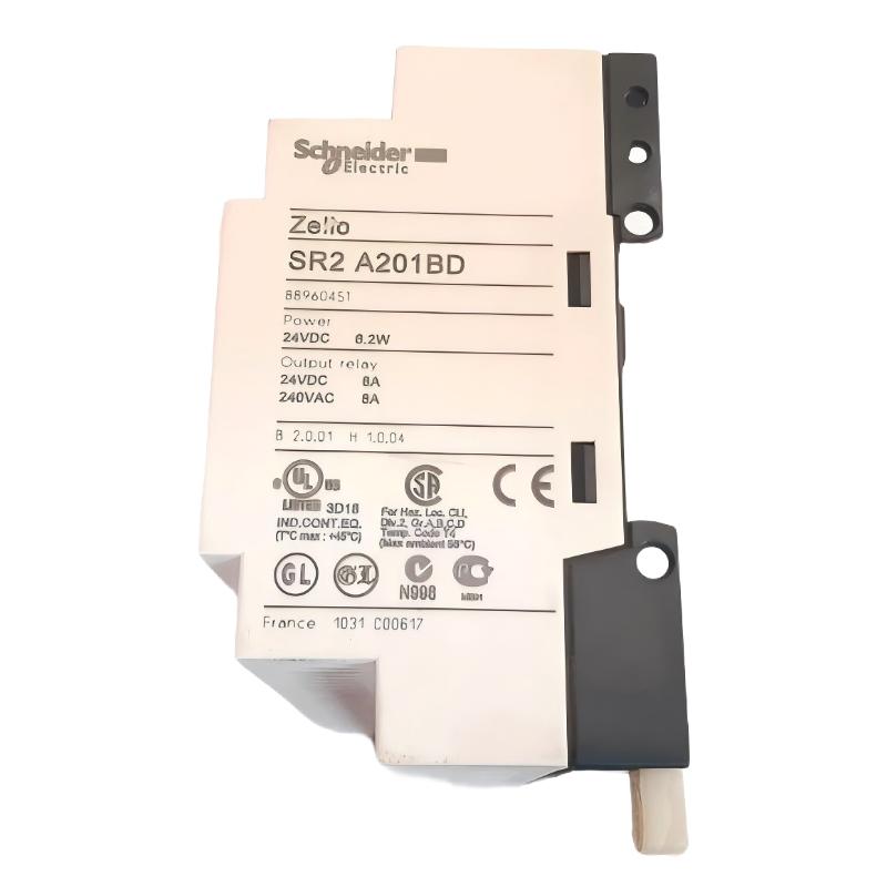
When purchasing the Schneider Electric SR2A201BD, verify the complete model number on the product label. The Zelio Logic family includes multiple models with similar appearances but different supply voltages, I/O arrangements, displays, and clock functions.
For replacement projects, confirm that the new unit provides the same 24 V DC supply arrangement, 12 digital inputs, two analog-capable channels, and eight relay outputs. Check the existing control program and terminal wiring before removing the installed device.
For used or surplus equipment, request clear photographs of the front display, terminal blocks, model label, and housing. Confirm that the LCD operates correctly and that the input and output channels have been tested where possible.
During routine maintenance, inspect terminal connections, power-supply stability, enclosure temperature, and the condition of connected field wiring. Keep a backup copy of the application program and document any modifications made during troubleshooting.
Because product availability may vary by region, confirm current stock and after-sales support before placing an order. If the original model is unavailable, evaluate a suitable Zelio Logic alternative or a current-generation controller after reviewing the complete application requirements.
Conclusion
The Schneider Electric SR2A201BD Zelio Logic Compact Smart Relay is a 24 V DC programmable controller designed for small industrial automation and building-control applications. Its 20-point I/O configuration combines 12 digital inputs, two analog-capable input channels, and eight relay outputs in a compact housing.
With an integrated LCD display, ladder and function block programming support, EEPROM program backup, and flexible mounting options, the SR2A201BD provides a practical solution for basic machine sequencing, pump control, ventilation, and auxiliary automation tasks.
For maintenance and replacement applications, verify the complete model number and electrical configuration before installation. Particular attention should be given to the absence of a real-time clock and the specific input and output requirements of the existing control system.