
NewsNEWCENTER
Featured products



Contact Us
Schneider Electric 140ACO13000 Analog Output Module Installation Guide: Wiring, Configuration, and Commissioning
2026-10-16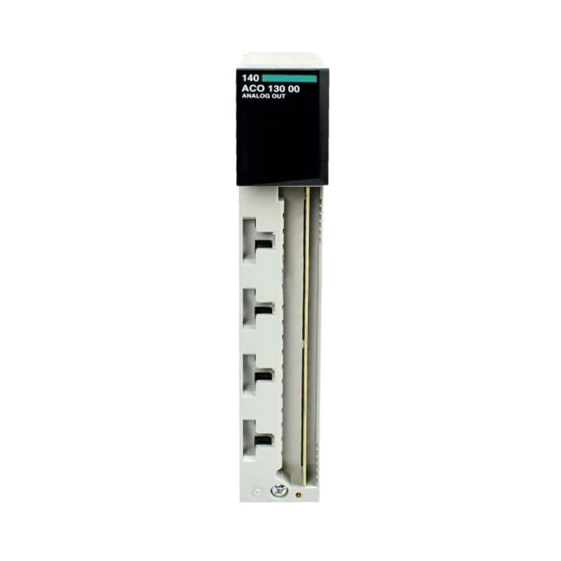
1. Product Overview
The Schneider Electric 140ACO13000 is an eight-channel, multirange analog output module designed for the Modicon Quantum PLC platform. It converts digital control values from a programmable logic controller into analog current signals for industrial field devices, including control valves, actuators, positioners, and process instruments. The 140ACO13000 supports configurable current output ranges of 0–20 mA, 0–25 mA, and 4–20 mA. This flexibility allows engineers to integrate different types of current-controlled equipment into a Quantum automation system. The module uses eight output words, with each word corresponding to an output channel. Installing the Schneider Electric 140ACO13000 requires careful attention to the external loop supply, current-sink wiring, channel configuration, output scaling, and field-device requirements. Correct commissioning should verify every channel independently before the module is released for process control. The 140ACO13000 is an established Modicon Quantum product. Its lifecycle status and replacement requirements should be considered when planning maintenance, spare-parts procurement, or migration to a newer automation platform.
2. Technical Specifications
| Parameter | Specification |
|---|---|
| Manufacturer | Schneider Electric |
| Model | 140ACO13000 |
| Product type | High-density analog output module |
| Automation platform | Modicon Quantum |
| Number of channels | 8 |
| Addressing requirement | 8 output words |
| Configurable output ranges | 0–20 mA, 0–25 mA, and 4–20 mA |
| External loop voltage | 6–30 V DC, subject to the specified loop operating conditions |
| Absolute accuracy error | ±0.2% of full scale at 25°C |
| Update time | Approximately 5 ms for all eight channels |
| Maximum power dissipation | 5 W |
| Bus current requirement | 550 mA |
| Diagnostic indicators | Active, external fault, and channel-status indicators |
| Output type | Current-sink output |
The exact raw-value representation depends on the selected output range and configuration. Confirm the valid register values, terminal assignments, loop wiring, and electrical limits in the documentation for the installed module.
3. Installation Preparation
3.1 Confirm the Module and Rack Configuration
Before installing the 140ACO13000, check the catalog number on the module label and verify that the intended Modicon Quantum rack and controller configuration support it. Review the following items:
- Confirm the module’s physical rack and slot assignment.
- Verify that the rack power supply has sufficient capacity for the complete system.
- Confirm that eight output words are available in the PLC I/O configuration.
- Identify the required output range for each field device.
- Verify the external loop supply voltage and field-device input requirements.
- Check the module’s current-sink wiring arrangement and terminal diagram.
- Determine the required output behavior during controller or module faults.
The 140ACO13000 is not interchangeable with every analog output module that fits a similar rack. Check the exact hardware and software compatibility before replacing or adding a module.
3.2 Prepare the Cabinet
Install the module in the designated slot according to the Quantum rack installation procedure. Ensure that the rack is secure, the module is fully seated, and the cabinet provides suitable ventilation and service access. Route analog signal cables away from motor power cables, variable-frequency drive outputs, contactors, and other sources of electrical interference. Use twisted-pair or shielded cable where appropriate for the installation environment, and follow the system’s grounding design.
3.3 Apply Electrical Safety Measures
Before handling the module or field wiring, assess the electrical hazards and follow the site’s lockout/tagout procedures. The module uses an external loop supply, which may remain energized even when rack power has been removed. Do not insert or remove the module under power unless the exact hardware configuration and manufacturer’s instructions explicitly permit that procedure. Verify that field devices can be safely isolated before conducting wiring or commissioning tests.
4. Understanding the Current-Sink Output
The 140ACO13000 uses current-sink outputs. In a typical current loop, the external DC supply and field device provide the loop circuit, while the module regulates the current by controlling the current path through its output channel. An illustrative functional arrangement is:
External DC Loop Supply
          |
          v
Compatible Field Device
          |
          v
140ACO13000 Output Channel
          |
          v
Loop Return
This is a conceptual diagram, not a terminal-level wiring schematic. Follow the module’s official wiring diagram to identify the correct supply, output, return, and field-device connections. Do not wire the module as though it were a voltage-output device or assume that it supplies loop power directly to every field instrument. Incorrect wiring can prevent the output from operating or damage connected equipment.
5. Wiring the 140ACO13000
5.1 Verify the External Loop Supply
The documented loop voltage range is 6–30 V DC, subject to the module’s specified operating conditions. Before connecting a field device, confirm that the external supply is suitable for both the module and the load. Calculate the required loop voltage by considering the field-device input requirements, cable resistance, and all other series voltage drops. Ensure that the available supply voltage is sufficient to maintain the commanded current without exceeding the permitted electrical limits. Do not increase the supply voltage beyond the documented range to compensate for incorrect wiring or excessive load resistance.
5.2 Connect the Output Channels
The module provides eight analog output channels. Use the correct terminal diagram to identify each channel’s output and associated return connection. Recommended wiring practices include:
- Label each channel at the module and field-device ends.
- Confirm the correct output range for each channel before connecting the load.
- Check the polarity and routing of the external loop supply.
- Use conductors appropriate for the installation environment.
- Keep analog wiring separate from high-current switching circuits.
- Verify that all return connections follow the manufacturer’s wiring diagram.
- Inspect for loose strands, accidental shorts, and damaged insulation.
The module documentation identifies the return terminals as internally common. Account for this shared-return arrangement when designing the external loop wiring and grounding system.
5.3 Check Field-Device Compatibility
Confirm that each connected device accepts the selected current range. A field device configured for 4–20 mA may not interpret a 0–20 mA signal in the intended way, and a 0–25 mA configuration should only be used when the receiving device supports it. Verify the device’s input resistance, polarity, required supply voltage, and expected response. For actuators and control valves, confirm that the electrical command corresponds to the correct mechanical direction and process response.
6. PLC Configuration and Output Scaling
6.1 Configure the Eight Output Words
Configure the module in the appropriate Quantum PLC engineering environment. Verify the physical rack and slot, module type, and output address allocation. The 140ACO13000 requires eight output words. Map each word to the intended field device and document the relationship between the PLC register, module channel, and process variable. After downloading the configuration, verify that the PLC recognizes the module and that no hardware or I/O configuration faults are reported.
6.2 Select the Correct Current Range
Choose the output range based on the receiving device and the application requirements. The module supports the following documented range options:
- 0–20 mA
- 0–25 mA
- 4–20 mA
The raw-value scaling differs by range and representation. Published module data includes range-dependent count mappings, including 0–20,000 counts for 0–20 mA, 0–25,000 counts for 0–25 mA, and two supported representations for 4–20 mA. Use the specific configuration and software documentation applicable to the installation rather than assuming one universal conversion.
6.3 Verify the Process Scaling
For a linear 4–20 mA control signal, the conceptual relationship between a normalized command and current is:
Output Current = 4 mA + (Normalized Command × 16 mA)
A normalized command of 0.0 corresponds to 4 mA, 0.5 corresponds to 12 mA, and 1.0 corresponds to 20 mA. For a 0–20 mA signal, the equivalent conceptual relationship is:
Output Current = Normalized Command × 20 mA
These equations illustrate engineering-unit scaling. They do not define the module’s raw register format. Verify the exact raw counts, endpoint handling, and data type in the applicable documentation.
6.4 Define Safe Output Behavior
Determine how each field device should respond if the PLC stops updating the output, the module develops a fault, or the control system loses communication. The correct response depends on the process and the device. A valve may need to close, open, or remain in a defined state depending on the hazard analysis and mechanical design. Do not assume that zero current is always the safest condition. Validate the selected response during an approved commissioning test before placing the equipment into service.
7. Commissioning Procedure
7.1 Complete Pre-Startup Checks
Before energizing the system, verify:
- The catalog number and rack slot are correct.
- The module is securely installed.
- The external loop supply is within the required range.
- Field wiring matches the approved terminal diagram.
- Each channel uses a compatible current range.
- The PLC output words are mapped correctly.
- The control process is in an approved test state.
7.2 Check Module Indicators
Restore power according to the system startup procedure. Check the Active indicator and review the external-fault and channel-status indicators. If a fault is present, record the indication and investigate the rack configuration, external loop supply, wiring, and channel setup before proceeding. Do not assume that the module is defective solely because a fault indicator is illuminated.
7.3 Test Each Output Channel
Test all eight channels individually using a suitable current measurement instrument or approved loop-testing equipment. Where practical, begin with a controlled test load rather than a live process actuator. For a channel configured for 4–20 mA, the following ideal test points are useful:
| Normalized Command | Expected Current |
|---|---|
| 0% | 4 mA |
| 25% | 8 mA |
| 50% | 12 mA |
| 75% | 16 mA |
| 100% | 20 mA |
For channels configured for 0–20 mA or 0–25 mA, use test points appropriate to the selected range. Actual acceptance tolerances should follow the module specifications and the site’s commissioning standard.
7.4 Verify Field-Device Operation
After the electrical signal has been verified, confirm that each field device responds correctly to the PLC command. Check direction of movement, control range, interlocks, and any configured response to loss of signal. Test one channel at a time wherever practical. This reduces the risk of unintended process changes and helps identify channel-specific wiring or scaling errors.
7.5 Document the Results
Record the module catalog number, rack and slot, channel mapping, output ranges, PLC register assignments, measured current values, and any corrective actions. This information provides a baseline for future maintenance and fault diagnosis.
8. Maintenance and Replacement Planning
The 140ACO13000 is a legacy Modicon Quantum module. Its commercial availability and service status vary by region, and it has been discontinued in several markets. Verify the current lifecycle status for the relevant location before planning procurement or long-term support. Schneider Electric identifies the Modicon X80 BMXAMO0802 as a potential replacement. However, this should not be treated as an automatic drop-in substitution. Rack architecture, controller compatibility, output characteristics, wiring, software configuration, and process behavior must be assessed before migration. Routine maintenance should include:
- Reviewing module and controller diagnostics.
- Inspecting wiring and external loop supplies.
- Checking terminal connections for corrosion or heat damage.
- Verifying output current during scheduled testing.
- Confirming the PLC scaling and channel assignments.
- Recording faults and corrective maintenance actions.
9. Frequently Asked Questions
How many channels does the Schneider Electric 140ACO13000 have?
The 140ACO13000 provides eight analog current output channels and requires eight output words in the PLC addressing configuration.
Which current ranges are supported?
The module supports 0–20 mA, 0–25 mA, and 4–20 mA ranges. Select the range that matches the connected field device and verify the corresponding raw-value scaling.
Does the module provide power to the field device?
The 140ACO13000 uses current-sink outputs and requires an appropriate external loop supply. Follow the exact wiring diagram to connect the supply and field device correctly.
Why is the external fault indicator illuminated?
Possible causes include an external loop or wiring problem, an open circuit in a configured 4–20 mA channel, or an issue involving unused channel configuration. Review the module diagnostics and the configured range of each channel.
Can the 140ACO13000 be replaced with a BMXAMO0802?
The BMXAMO0802 is identified as a potential replacement, but compatibility must be evaluated at the system level. Confirm the controller, rack, configuration, wiring, current range, and process response before carrying out a migration.
10. Technical Summary
The Schneider Electric 140ACO13000 is an eight-channel multirange analog output module for Modicon Quantum PLC systems. It supports 0–20 mA, 0–25 mA, and 4–20 mA signals and uses current-sink outputs with an external loop supply. Successful installation depends on correct loop wiring, appropriate output-range selection, accurate PLC scaling, and channel-by-channel commissioning. Because the module is a legacy product, replacement planning should include a full compatibility assessment rather than relying on catalog-number similarity alone.