
NewsNEWCENTER
Featured products



Contact Us
Schneider Electric 140ACO13000 Troubleshooting Guide: Output Faults, Current Loop Diagnosis, and Repair
2026-10-16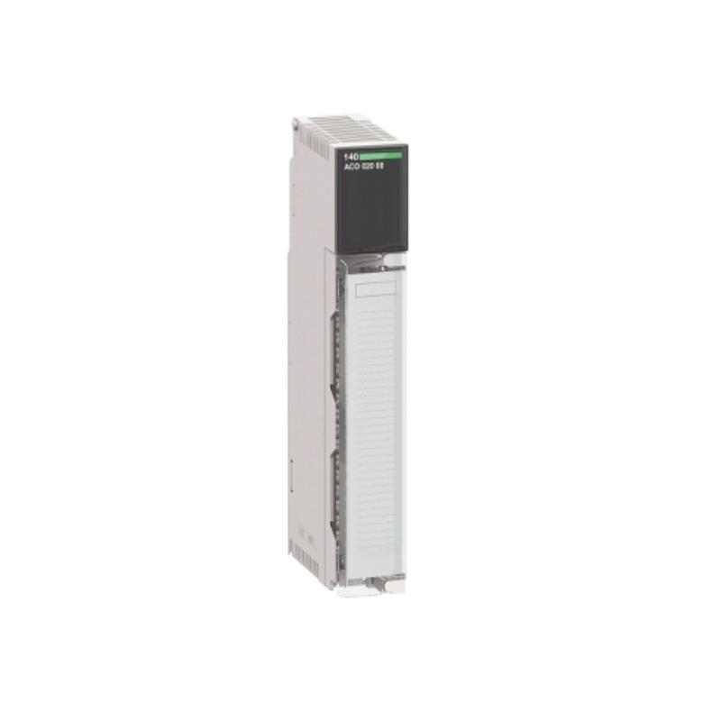
1. Product Overview
The Schneider Electric 140ACO13000 is an eight-channel multirange analog output module used in Modicon Quantum PLC systems. It converts digital control values into analog current signals for compatible industrial field devices, including control valves, actuators, positioners, and process instruments. The module supports 0–20 mA, 0–25 mA, and 4–20 mA output ranges. Each channel is assigned an output word in the PLC configuration, and the module uses current-sink outputs that operate with an appropriate external loop supply. Typical problems include a missing current signal, an incorrect output value, an illuminated fault indicator, a broken-wire warning, or a field device that does not respond to the PLC command. A systematic diagnostic process helps distinguish between a module fault, an external wiring problem, a loop-supply issue, incorrect register scaling, and a downstream device failure.
2. Safety Precautions
Analog outputs may control valves, actuators, and other equipment that can change the process state. Changing an output value during troubleshooting can cause unexpected movement or process disturbances. Before testing, obtain the required authorization and place the controlled equipment in an approved maintenance state. Follow the site’s lockout/tagout procedures before handling wiring or hardware. The module uses an external loop supply. That supply may remain energized even when rack power is removed. Verify the safe state of the relevant circuits before disconnecting conductors or measuring resistance. Do not short output terminals, bypass process interlocks, or remove the module under power unless the exact system configuration and manufacturer instructions explicitly permit the procedure.
3. Common Fault Symptoms and Possible Causes
| Symptom | Possible Causes | Recommended First Check |
|---|---|---|
| No output current | Missing external loop supply, open circuit, incorrect wiring, wrong output register, or module fault | Check supply voltage, channel mapping, and loop continuity |
| Current remains at zero | PLC command is zero, channel is incorrectly configured, output circuit is open, or external supply is absent | Verify the raw output value and loop supply |
| Output is below the commanded value | Excessive load resistance, voltage drop, poor connection, or scaling error | Measure loop current and verify the voltage budget |
| Output is higher than expected | Incorrect scaling, wrong range selection, or program logic error | Check the selected range and PLC conversion |
| Red channel fault indicator | Possible broken wire or channel-related fault | Inspect the affected loop and module diagnostics |
| External fault indicator is on | External wiring or loop condition, or an unused channel configured in an unsuitable range | Review all channel configurations and wiring |
| Signal fluctuates | Changing PLC command, unstable loop supply, interference, or loose wiring | Compare PLC trends with measured current |
| Field device does not respond | Incorrect signal, field-device fault, interlock, or mechanical problem | Verify the current signal and device status separately |
These are possible causes rather than definitive diagnoses. Use the actual LED indications, PLC diagnostics, and model-specific documentation to determine the correct troubleshooting path.
4. Troubleshooting a Missing Output Signal
4.1 Verify the External Loop Supply
The 140ACO13000 requires an external loop supply within its specified operating range. Measure the supply using an appropriate instrument and verify that the voltage is within the documented 6–30 V DC range under the actual circuit conditions. A supply may have the correct nominal voltage but fail under load because of a weak source, poor connection, or excessive voltage drop. Where the approved procedure permits, compare the supply voltage at its source and at the field circuit. Do not increase the supply voltage beyond the module’s permitted limits to force an output to operate.
4.2 Check the PLC Output Word
Verify that the PLC program is writing the intended value to the correct output word. The 140ACO13000 has eight output channels and requires eight output words. Confirm that the register mapping matches the physical channel and field device. Check for incorrect addressing, inactive program logic, unexpected limits, or forced values left over from previous maintenance. If the PLC command is incorrect, correct the control logic through the site’s approved change-control procedure before investigating the analog hardware further.
4.3 Inspect the Wiring
After placing the process in a safe state and isolating the relevant circuit, inspect the affected output loop for disconnected conductors, loose terminals, incorrect polarity, damaged cable, and wiring errors. Use the exact module wiring diagram to verify the output, return, and external supply connections. The return terminals are internally common, so the wiring design must account for this shared connection. Never assume that a terminal arrangement from a different analog output module is applicable to the 140ACO13000.
4.4 Measure the Current
Use suitable current measurement equipment and an approved measurement method. If measuring current requires opening the loop, isolate the circuit and follow the correct procedure before inserting the instrument. Compare the measured current with the commanded value and the configured output range. If the PLC command is correct but the current remains absent, continue checking the loop supply, wiring, load, and channel diagnostics.
5. Diagnosing Incorrect Current Values
5.1 Confirm the Configured Range
The 140ACO13000 supports several output ranges. If the PLC program, module configuration, and receiving device use different ranges, the current may not correspond to the expected engineering value. Confirm whether the channel is configured for 0–20 mA, 0–25 mA, or 4–20 mA. Check the corresponding raw-value range and verify that the field device is configured to interpret the signal correctly. Do not assume that all ranges use the same raw-value endpoints.
5.2 Check PLC Scaling
For a normalized command between 0.0 and 1.0, the ideal current relationship is:
For 4–20 mA:
Current = 4 mA + (Normalized Command × 16 mA)

For 0–20 mA:
Current = Normalized Command × 20 mA

For 0–25 mA:
Current = Normalized Command × 25 mA
These formulas describe ideal engineering scaling, not the module’s exact register format. Confirm the raw counts and numeric representation for the selected configuration. Common scaling errors include:
- Using the wrong full-scale raw value.
- Applying the conversion twice.
- Writing to the wrong output word.
- Using the 4–20 mA formula for a 0–20 mA channel.
- Applying integer rounding or truncation incorrectly.
- Leaving a temporary forced value active.
5.3 Check the Loop Voltage Budget
The external supply must provide enough voltage to drive the selected current through the field device, wiring, and other series components. Use the following relationship to estimate the resistive voltage drop:
Voltage Drop = Loop Current × Total Loop Resistance
Include cable resistance and the field-device input characteristics. Compare the calculated requirement with the available supply voltage and the module’s permitted operating conditions. If the current is too low, check for excessive load resistance, poor connections, or an unsuitable external supply before concluding that the output channel has failed.
6. Diagnosing Broken-Wire and Channel Fault Indicators
6.1 Identify the Affected Channel
The module provides channel-status indicators, including red indicators associated with channel faults. Record which channel is affected and whether the Active indicator shows that bus communication is present. Use the PLC diagnostic information and the wiring diagram to identify the corresponding field circuit. Avoid changing multiple channels simultaneously, as this can make the original fault more difficult to isolate.
6.2 Check for an Open Loop
An open-circuit condition may occur because of a disconnected conductor, loose terminal, failed field device, or incorrect external wiring. In 4–20 mA mode, the module can detect a broken-wire condition. After isolating the circuit, inspect the relevant wiring and terminations. Verify the field device’s connection and confirm that the loop is complete according to the approved schematic.
6.3 Review Unused Channel Configuration
An unused output channel may contribute to an external fault indication if it is configured in a way that causes the module to detect an unexpected loop condition. The module documentation specifically notes that unused outputs should be configured in the 0–25 mA range to avoid this issue. Before changing channel configuration, verify which channels are genuinely unused and confirm that the proposed setting is consistent with the installed system design. Do not alter a channel that serves an active process device simply to clear an indicator.
7. Troubleshooting Fluctuating or Unstable Signals
7.1 Compare Command Values with Measured Current
Trend the PLC output command and compare it with the measured current over the same period. If the current changes in step with the command, investigate the control program, process feedback, scaling, and output limits. If the PLC command remains stable while the current fluctuates, inspect the loop supply, cable routing, connections, and field device.
7.2 Inspect Analog Wiring and Grounding
Electromagnetic interference from drives, contactors, switching supplies, and motor cables can affect analog circuits. Inspect the cable route and confirm that shielding and grounding follow the installation design. Do not add arbitrary ground connections or alter shield termination without understanding the system’s grounding arrangement. Unintended ground paths can introduce additional signal problems.
7.3 Check Supply and Connection Stability
A loose terminal or unstable loop supply can cause intermittent output behavior. Inspect connections after safe isolation and measure the external supply under representative operating conditions. If the signal remains unstable after the external circuit and PLC command have been verified, evaluate the module using the manufacturer’s diagnostic procedure.
8. Diagnosing Rack and Module Configuration Problems
If the PLC does not recognize the module or reports a hardware configuration fault, check the rack and controller configuration before assuming that the analog output electronics have failed. Review these items:
- Confirm the physical rack and slot assignment.
- Verify that the configured module type matches the installed 140ACO13000.
- Check rack power supply status and capacity.
- Review the eight output-word assignments.
- Inspect the module seating and rack connector after safe isolation.
- Review recent hardware configuration changes or module replacements.
If a replacement module has been installed, verify that the software configuration and wiring are appropriate for the exact device. Similar-looking analog modules may differ in current ranges, raw-value conventions, or electrical characteristics.
9. Repair and Replacement Considerations
Before replacing the module, confirm that the external loop supply, field wiring, PLC command, output range, and receiving device have been checked. If the problem remains associated with the same channel under a verified test setup, qualified evaluation or module replacement may be necessary. Do not attempt unauthorized component-level repair of the electronic assembly. The 140ACO13000 is a legacy product, and replacement planning should include compatibility checks. Schneider Electric identifies the Modicon X80 BMXAMO0802 as a potential replacement, but it is not automatically a direct drop-in substitute for every Quantum installation. Before migration, verify:
- Controller and rack architecture.
- Output range and current-sink behavior.
- Electrical limits and field-device requirements.
- PLC configuration and software changes.
- Wiring and terminal compatibility.
- Process behavior during faults and loss of control.
Any platform migration should be treated as a controlled engineering change, followed by appropriate commissioning and functional testing.
10. Preventive Maintenance Checklist
A consistent maintenance program can reduce recurring analog output problems.
- Review the Active and fault indicators during routine inspections.
- Check PLC diagnostics for repeated channel faults.
- Inspect loop wiring, external supplies, and terminal connections.
- Verify output current at approved test points.
- Confirm that raw-value scaling matches the configured current range.
- Review the configuration of unused channels.
- Document recurring faults, measured values, and corrective actions.
Maintain baseline test results for all eight channels. Comparing current measurements with previous records can help identify gradual changes in signal accuracy, wiring condition, or field-device performance.
11. Frequently Asked Questions
Why is the 140ACO13000 fault indicator illuminated?
Possible causes include an external loop fault, an open circuit in a channel configured for 4–20 mA, or an unused channel configured in an unsuitable range. Check the channel indicators, wiring, and configuration before replacing the module.
Why does an output remain at zero current?
Possible causes include a zero PLC command, incorrect register mapping, missing loop power, an open circuit, or a module fault. Check the command value and external loop conditions first.
Can I use the same raw-value scaling for every output range?
No. The module supports multiple current ranges and range-dependent raw-value mappings. Verify the selected range and corresponding register scaling in the applicable configuration documentation.
Why is the measured current lower than the commanded value?
Possible causes include excessive loop resistance, insufficient external supply voltage, poor wiring connections, incorrect scaling, or a channel fault. Check the complete loop rather than focusing on the module alone.
What should I check before replacing the module?
Verify the rack configuration, PLC output word, selected current range, external loop supply, wiring, and field-device condition. If the fault remains associated with the module after these checks, qualified evaluation or replacement may be appropriate.
12. Technical Summary
The Schneider Electric 140ACO13000 is an eight-channel multirange analog output module for Modicon Quantum PLC systems. Effective troubleshooting requires checking the PLC output words, selected current ranges, external loop supply, current-sink wiring, channel diagnostics, and field-device response. A missing or incorrect current signal does not automatically indicate a failed module. Systematic measurement, careful configuration review, and documented maintenance help isolate faults while reducing unnecessary replacements and process downtime.