
NewsNEWCENTER
Featured products



Contact Us
Schneider Electric 140ACO02000C Troubleshooting Guide: Analog Output Faults, Signal Testing, and Maintenance
2026-10-16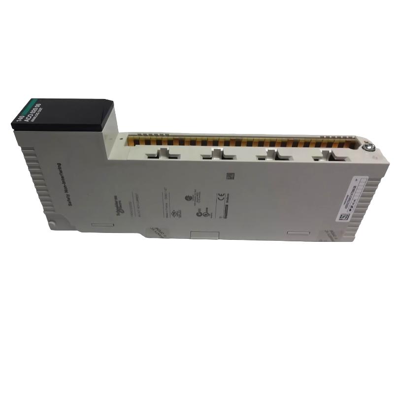
1. Product Overview
The Schneider Electric 140ACO02000C is a four-channel analog output module designed for the Modicon Quantum PLC platform. It generates 4–20 mA current signals that allow a PLC to control compatible field devices, including control valves, actuators, process instruments, and equipment that accepts an analog current reference. When the module operates incorrectly, symptoms may include a missing output signal, a current value that does not match the PLC command, one channel reporting a fault, a field device that fails to respond, or an intermittent analog signal. These symptoms do not automatically indicate a defective module. The cause may be in the PLC program, rack configuration, field wiring, external loop supply, connected load, or downstream equipment. A reliable troubleshooting procedure begins by documenting the symptom and checking the module’s status indicators. The next steps are to verify the PLC output value, inspect the current loop, measure the signal under safe conditions, and compare the results with the expected 4–20 mA range.
2. Safety Precautions Before Troubleshooting
Analog output circuits can control equipment that moves, changes pressure, regulates temperature, or affects other process variables. Changing an output value may cause a valve or actuator to move unexpectedly. Before testing, place the controlled process in an approved maintenance or test state. Notify affected personnel and confirm that any required interlocks and process protections remain active. Follow the manufacturer’s instructions for removing or inserting the module. Do not assume that the module supports hot swapping in every rack configuration. Where required, isolate power and apply lockout/tagout procedures before handling wiring or hardware. Never short output terminals deliberately to test the module. Use suitable measurement equipment and approved test procedures.
3. Common Symptoms and Possible Causes
| Symptom | Possible Causes | Initial Diagnostic Action |
|---|---|---|
| No current output | Incorrect PLC value, output disabled, open loop, wiring fault, or module fault | Check PLC register values, status indicators, and loop continuity |
| Output remains near 4 mA | PLC command at minimum, incorrect scaling, or fixed output command | Verify the intended command and raw output value |
| Output remains near 20 mA | Maximum command, scaling error, forced value, or incorrect program logic | Review the command value, program logic, and any active forcing |
| Current differs from the PLC command | Incorrect scaling, excessive loop resistance, measurement error, or output-channel problem | Compare raw data, calculated current, and measured loop current |
| One channel fails while others work | Channel wiring fault, open loop, field-device fault, or damaged output channel | Inspect the affected loop and compare diagnostics with other channels |
| Signal fluctuates | Electrical interference, unstable loop supply, poor connection, or changing PLC command | Compare command trends with measured current and inspect wiring |
| PLC reports a module fault | Rack configuration issue, module seating problem, power issue, or hardware fault | Review rack diagnostics and module status indicators |
| Field device does not move | Incorrect current signal, actuator fault, interlock, or mechanical problem | Verify the electrical command and inspect the field device separately |
These are possible causes, not definitive fault codes. Use the module’s actual indicators and the system diagnostic information to narrow the investigation.
4. Troubleshooting a Missing 4–20 mA Output
4.1 Verify the PLC Command
Start by checking the output value written by the PLC program. Confirm that the program is executing as intended, the correct output word is being updated, and no force, override, or fallback routine is holding the output at an unexpected value. The 140ACO02000C uses four output words for its four channels. Verify that each field device is associated with the correct channel and register. A valid-looking PLC value does not necessarily prove that the module is generating the expected current. Continue with the electrical checks if the program and mapping appear correct.
4.2 Inspect the Module Status
Observe the module’s status indicators and review any rack or controller diagnostic messages. Record the indications before making changes. If the PLC does not recognize the module, verify the rack and slot configuration, module seating, and rack power supply. Follow the applicable hardware maintenance procedure before reseating or replacing the module. If only one channel is affected, focus first on that channel’s wiring, loop load, and field device rather than immediately replacing the complete module.
4.3 Check the Current Loop
A missing current signal can result from an open circuit, incorrect terminal assignment, a disconnected field device, or an unsuitable loop supply arrangement. Using the approved test procedure, inspect the complete signal path from the module through the field wiring to the receiving device. Verify the output and return connections against the exact wiring diagram. Do not infer terminal numbers from a similar Quantum module. Confirm the correct connection diagram for the 140ACO02000C.
4.4 Measure the Output Signal
Use an appropriately rated instrument and a measurement method suitable for the circuit. If the circuit must be opened to insert a current meter, isolate the circuit and follow the approved procedure before changing connections. Compare the measured current with the PLC command and expected scaling. If the PLC command changes but the measured current does not, investigate the module configuration, channel wiring, load, and diagnostic status. If the module produces the expected current at an approved test point but the field device does not respond, investigate the field device and its control logic separately.
5. Diagnosing Incorrect Output Current
5.1 Check Analog Scaling
A 4–20 mA output represents a normalized command over a 16 mA span. Incorrect conversion between engineering units and the raw output word can cause the current to differ from the expected value. For a linear mapping:
Current (mA) = 4 + (Normalized Command × 16)
For example, a normalized command of 0.25 corresponds to an ideal current of 8 mA, while 0.75 corresponds to 16 mA. These are illustrative values. The actual raw-value range, register representation, and endpoint conventions must be verified against the installed module’s documentation and the PLC program. Check for common programming issues:
- Using a raw-value range from a different analog module.
- Scaling the command twice in separate program routines.
- Using the wrong output register for a channel.
- Applying a limit or clamp that prevents the intended value.
- Using an integer conversion that truncates intermediate calculations.
- Leaving a force or test value active after maintenance.
5.2 Check Loop Voltage and Load Resistance
The external loop must have sufficient voltage to maintain the required current through the field device and all series resistance. Excessive load resistance can prevent the current from reaching the commanded value. Calculate the expected voltage drop using the actual loop current and total resistance:
Voltage Drop = Loop Current × Total Loop Resistance
Include the receiving device, cable resistance, and any additional series components. Compare the result with the permitted operating conditions for the module and the connected equipment. Do not increase the loop supply voltage beyond the module’s documented limits to compensate for a wiring or load problem.
5.3 Compare the Channel with a Known-Good Channel
If one channel is abnormal, compare its PLC configuration, signal wiring, and diagnostic state with a functioning channel. This comparison can reveal an incorrect register assignment or an external circuit problem. Do not swap live conductors between channels without an approved procedure. Before any channel substitution test, confirm that the field devices can tolerate the change and that the test will not cause an unsafe process response.
6. Troubleshooting Channel Faults and Open Loops
The module’s channel indicators and diagnostic information can help identify a channel that is not operating as expected. For a 4–20 mA circuit, an open loop may prevent the required current from flowing.
6.1 Inspect Wiring and Terminations
Check the affected loop for disconnected conductors, loose terminals, damaged cable, corrosion, or incorrect polarity. Confirm that the field device is connected to the intended output channel. Inspect terminal blocks and intermediate junctions where a loose connection may be intermittent. Make corrections only after following the required isolation and process-safety procedures.
6.2 Verify the Field Device
A defective actuator, positioner, or receiving instrument can make a functioning output channel appear faulty. Verify the device’s input specifications and confirm that it is powered and enabled as required. If the field device has its own diagnostic indicators, alarms, or input-status display, compare those indications with the measured loop current.
6.3 Determine Whether the Fault Follows the Wiring
When the system design permits, an approved test using a known-good load can help distinguish an external circuit problem from a module-channel problem. If the fault remains associated with the same physical channel after external wiring and load conditions have been verified, the channel may require further evaluation. If the fault follows the field wiring or device, investigate that external circuit instead. Do not perform channel substitution on a live process without a documented risk assessment and authorization.
7. Troubleshooting Fluctuating or Unstable Signals
7.1 Compare the PLC Trend with the Measured Current
First determine whether the PLC command itself is changing. Trend the output command and compare it with the measured current over the same period. If the command changes in step with the current, inspect the control algorithm, process feedback, scaling, and output limits. If the command remains stable while the current fluctuates, focus on the electrical loop, connections, interference, and module behavior.
7.2 Inspect Analog Cable Routing
Analog signal wiring can be affected by electromagnetic interference from drives, contactors, switching power supplies, and high-current conductors. Inspect the cable route and grounding arrangement. Use the shielding and segregation practices specified for the complete control system. Avoid creating unintended ground paths or changing shield termination without understanding the installation’s grounding design.
7.3 Check Connections and Loop Supply Stability
A loose connection or unstable external supply can produce intermittent signal behavior. Check the relevant connections and measure the loop supply under representative operating conditions. If signal instability remains after the wiring, power source, and PLC command have been verified, evaluate the channel using the manufacturer’s recommended diagnostic procedure.
8. Diagnosing Rack and Configuration Problems
If the PLC reports a module configuration fault or fails to recognize the 140ACO02000C, investigate the system-level configuration before assuming that the analog circuitry is defective. Check the following:
- Confirm the module’s physical rack and slot.
- Verify that the configured module type matches the installed catalog number.
- Review rack power supply status and capacity.
- Inspect the module’s seating and rack connector condition after safe isolation.
- Check the PLC’s I/O map and output word allocation.
- Review recent configuration changes, downloads, and maintenance activity.
If the module has been replaced, confirm that the configuration and wiring still match the replacement device. A module with a similar appearance or function may not have identical output ranges, register conventions, or compatibility requirements.
9. Repair, Replacement, and Maintenance Decisions
Troubleshooting should establish whether the fault is caused by external wiring, the PLC program, the loop supply, the field device, or the module itself. External wiring faults can often be corrected by qualified personnel after the circuit has been made safe. Programming problems should be corrected through the site’s approved change-control process. A field-device fault should be handled according to the device manufacturer’s service procedure. If a module channel remains faulty after the external circuit and configuration have been verified, consider qualified repair or replacement. Do not attempt component-level repair of the electronic assembly without the appropriate service capability and authorization. When considering a replacement, verify:
- Compatibility with the existing Quantum rack and controller.
- Four-channel 4–20 mA output functionality.
- Output electrical limits and isolation characteristics.
- PLC software and configuration requirements.
- Terminal wiring and field-device compatibility.
- Output behavior during faults and loss of PLC control.
A migration to a different automation platform may require changes to hardware, software, wiring, and commissioning procedures. Treat it as an engineering change rather than a simple module swap.
10. Preventive Maintenance Checklist
A planned maintenance routine helps identify signal problems before they cause process interruptions.
- Review PLC and rack diagnostics for recurring module or channel faults.
- Inspect field wiring, terminal blocks, and cable insulation.
- Verify that analog signal cables remain properly routed and shielded.
- Check output current at approved test points during scheduled maintenance.
- Confirm that PLC scaling and register mapping remain correct.
- Remove obsolete test forces and temporary overrides after maintenance.
- Record measured values, corrective actions, and replacement history.
Maintain baseline measurements for each channel. Comparing current test results with earlier readings can help identify gradual degradation, wiring resistance changes, or recurring field-device problems.
11. Frequently Asked Questions
Why does the 140ACO02000C output stay at 4 mA?
The PLC may be commanding the minimum of the 4–20 mA range, or the program may be using incorrect scaling or a forced value. Check the raw output word, channel mapping, and program logic before diagnosing a hardware fault.
Why does one output channel fail while the other three work?
Possible causes include an open loop, poor terminal connection, a faulty field device, incorrect channel mapping, or a damaged output channel. Check the affected circuit and its diagnostics before considering module replacement.
Can the output module be tested without the field device?
An approved test load or suitable measurement setup can help isolate the module from the field device. The test must follow the module’s electrical limits and the site’s safety procedures.
What causes a 4–20 mA signal to fluctuate?
Possible causes include a changing PLC command, electrical interference, unstable loop power, poor connections, excessive load resistance, or a channel fault. Compare the PLC trend with measured current to narrow the cause.
When should the module be replaced?
Replacement should be considered after the rack configuration, PLC command, external wiring, loop supply, and field device have been checked. If the abnormal behavior remains associated with the module under a verified test setup, qualified evaluation or replacement may be appropriate.
12. Technical Summary
The Schneider Electric 140ACO02000C is a four-channel, 4–20 mA analog output module for Modicon Quantum PLC systems. Troubleshooting should proceed systematically from PLC command and register scaling to module diagnostics, loop wiring, external power, load resistance, and field-device operation. Accurate measurements and controlled testing are more reliable than replacing a module based on symptoms alone. By documenting fault conditions, checking the complete current loop, and maintaining verified configuration records, engineers can reduce downtime and maintain dependable analog control in industrial automation systems.