

ProductPRODUCT
Featured products
Contact Us
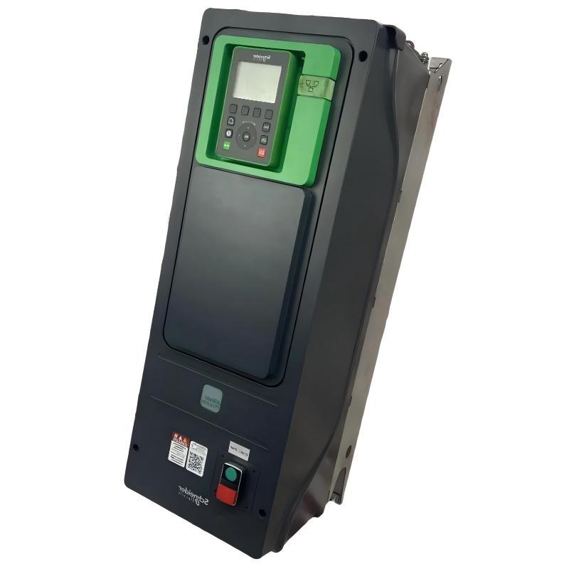
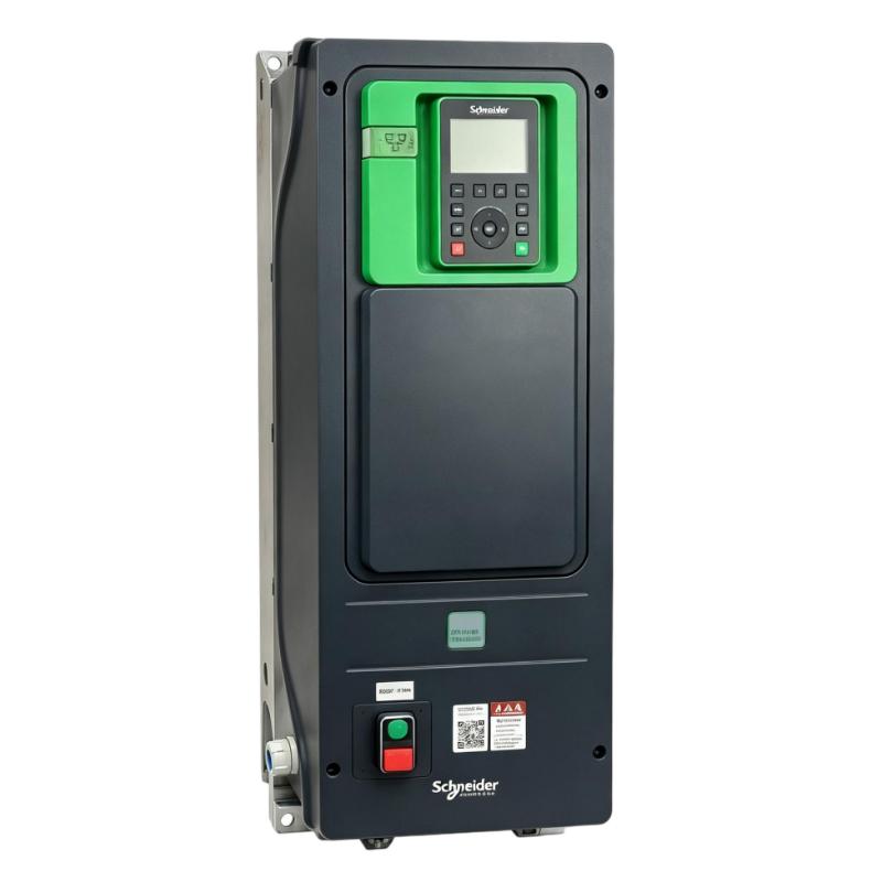
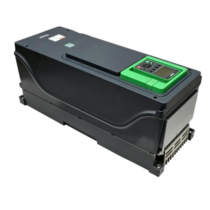
- Schneider
- ATV650U07N4E
- Variable Speed Drive
- France
- 264 x 678 x 300 mm
- 10.5 kg
- Xiamen, China
- New & In Stock
- T/T, PayPal, Western Union
- 1 Year
- 1-3 Working Days
- DHL, UPS, TNT, FedEx and EMS.
- 24-Hour Service
- COO
- 2
Our advantage

Global Logistics
We have a 10-year logistics and express cooperation agreement, so our products can be shipped to any place in the world.

Brand new and original
Our products are imported in bulk from the place of origin. Because of the cooperative relationship, our products are all original and 100% new.

24-hour service
We provide 7*24 hours service to our customers. We will be there whenever you need us.

Price advantage
All our products are priced very favorably because we have our own warehouse and supply.
| Company Information | |||
| [email protected] | |||
| Mobile | +8615980777398 | ||
| +8615980777398 | |||
| 15980777398 |
Product Overview
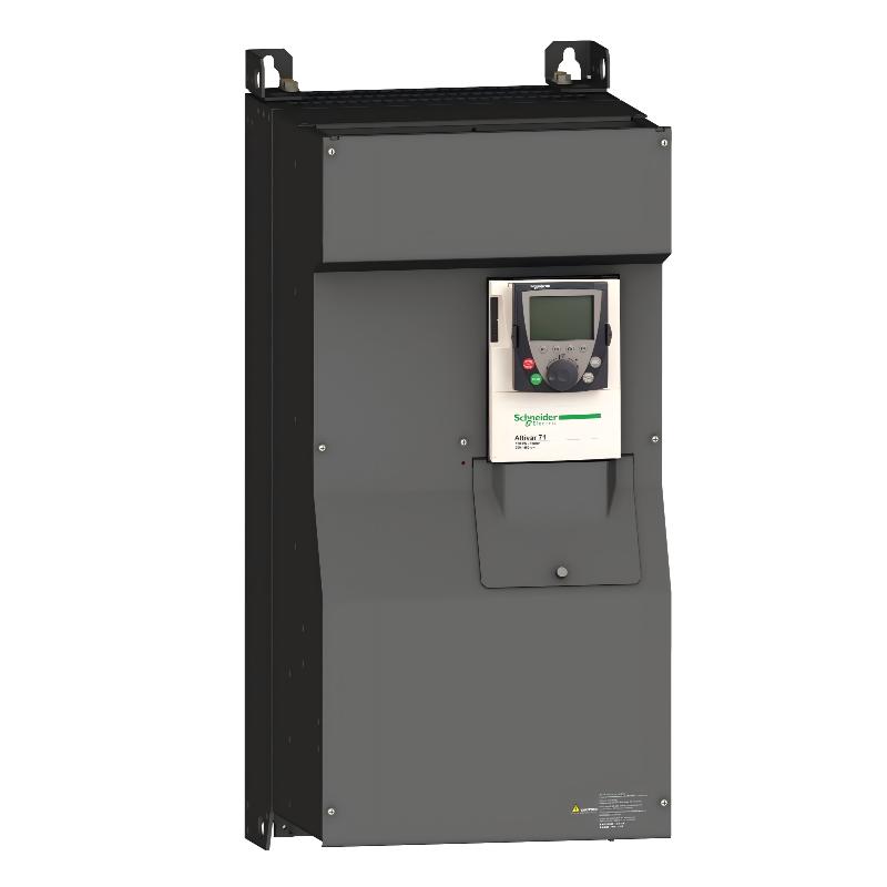
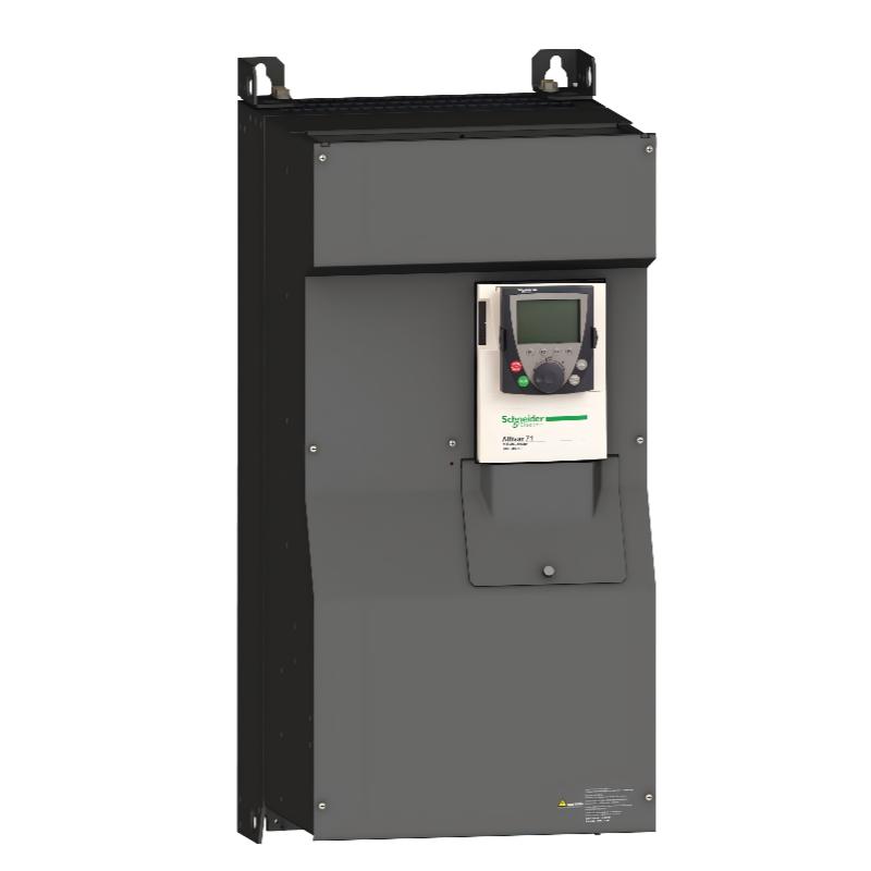
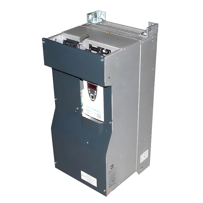
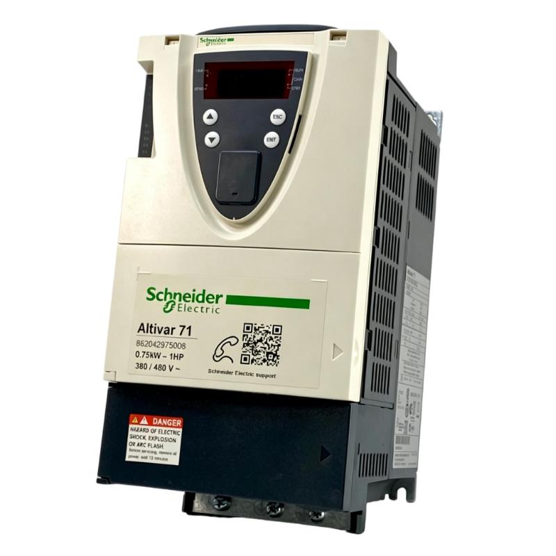
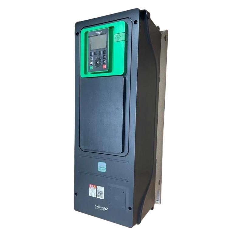
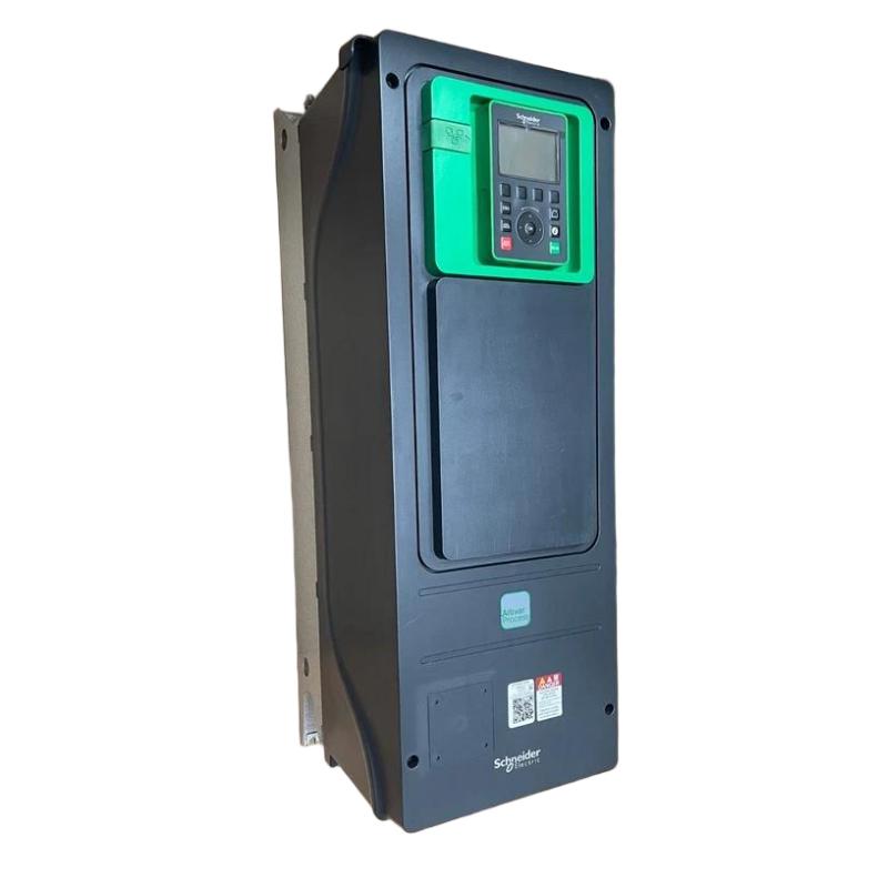
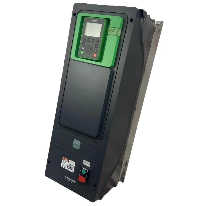
The Schneider Electric ATV650U07N4E Variable Speed Drive is an industrial motor control device from the Altivar Process ATV650 series, developed for applications requiring precise variable-speed operation, reliable motor control, process optimization, and integration with industrial automation systems. The drive is designed for use in process-oriented environments where motors need to respond efficiently to changing operating conditions rather than simply running at a fixed speed.
The ATV650U07N4E is associated with the 0.75 kW motor power class and can be applied to suitable pumps, fans, ventilation systems, HVAC equipment, water-treatment machinery, and other industrial process equipment. By controlling the frequency and voltage delivered to an AC motor, the drive enables controlled acceleration, deceleration, and operating speed.
For equipment planning and replacement purposes, the specified physical dimensions of the Schneider ATV650U07N4E are 264 × 678 × 300 mm, with a specified weight of 10.5 kg. These physical characteristics should be considered when designing electrical cabinets, planning transportation, and preparing maintenance access.
The ATV650 series is intended to work as part of a broader automation architecture. Depending on the installed configuration and system design, the drive can be connected with PLC, DCS, HMI, and SCADA systems to provide motor commands, operating information, alarms, and diagnostic data.
Technical Specifications
| Parameter | Specification |
|---|---|
| Manufacturer | Schneider Electric |
| Model | ATV650U07N4E |
| Product Family | Altivar Process ATV650 |
| Product Type | Variable Speed Drive / Variable Frequency Drive |
| Motor Power Class | 0.75 kW |
| Application | Industrial motor speed control |
| Drive Function | Variable-speed AC motor control |
| Control Functions | Speed regulation, acceleration, deceleration, motor monitoring |
| Automation Integration | PLC, DCS, HMI, SCADA |
| Typical Applications | Pumps, fans, HVAC, ventilation, process equipment |
| Installation | Industrial cabinet / suitable enclosure |
| Cooling | Forced-air cooling architecture |
| Dimensions | 264 × 678 × 300 mm |
| Weight | 10.5 kg |
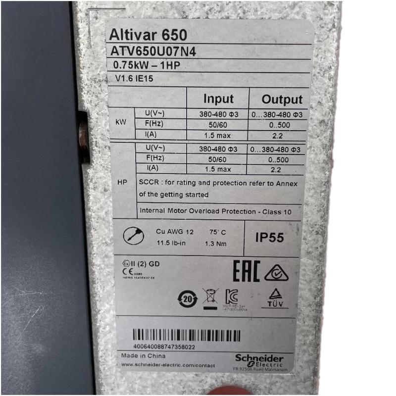
Exact electrical ratings, input/output characteristics, overload capability, terminals, communication interfaces, environmental specifications, accessories, and option compatibility should be verified against the actual product nameplate and applicable configuration documentation.
What Is the Schneider ATV650U07N4E?
The ATV650U07N4E is a Schneider Electric Altivar Process variable speed drive designed to regulate the operation of compatible AC motors.
In a conventional fixed-speed motor installation, the motor normally receives power at a fixed frequency and operates close to a predetermined speed. This approach can be inefficient when the process does not continuously require maximum motor output.
A variable speed drive introduces electronic control between the power source and motor:
AC Power → ATV650U07N4E → Variable-Frequency Output → AC Motor → Process Load
The drive electronically regulates the motor supply, allowing motor speed to be adjusted according to process requirements.
This approach is especially useful in systems where flow, pressure, ventilation, circulation, or mechanical output varies during normal operation.
ATV650U07N4E Working Principle
The drive uses power-electronic conversion to control the electrical energy supplied to the motor.
AC Power Conversion
The incoming AC power is processed by the drive’s input power stage.
DC-Link Stage
The incoming electrical energy is converted into an intermediate DC-link voltage. This stage provides the energy source for the inverter.
Inverter Stage
The inverter uses electronic switching to create a controlled AC output waveform. Output frequency and voltage are adjusted according to the motor-control requirements.
Motor Speed Control
Motor speed is closely related to the frequency of the supplied electrical waveform. By controlling the output frequency, the ATV650U07N4E can regulate motor operating speed.
Process Response
The motor transfers mechanical energy to the connected load. The drive can then adjust operation according to control commands or process feedback.
This creates a flexible control loop suitable for automated industrial equipment.
Motor Speed Regulation
One of the primary benefits of the ATV650U07N4E is its ability to adapt motor operation to changing process requirements.
For example, a pump may require high flow during one operating condition and considerably lower flow during another. Instead of keeping the motor at full speed and controlling the process through mechanical restrictions, variable-speed operation can allow the motor to operate closer to the required condition.
The same principle can be applied to fans and ventilation systems.
Common motor-control functions include:
- Start and stop control
- Adjustable acceleration
- Adjustable deceleration
- Variable-speed operation
- Process-oriented control
- Motor monitoring
- Alarm detection
- Fault management
- Remote control
- Operating-status feedback
The exact control functions available depend on the product configuration and application settings.
Role in Industrial Automation
The ATV650U07N4E can operate as a field-level motor-control component within an industrial automation system.
A typical architecture may be represented as:
PLC / DCS → Communication or Control Interface → ATV650U07N4E → Motor → Process
The controller determines the required motor operating condition, while the drive converts that command into controlled electrical output for the motor.
At the same time, drive information can be returned to the automation system.
Typical monitored information may include:
- Drive operating state
- Run status
- Stop status
- Speed reference
- Actual operating condition
- Alarm state
- Fault status
- Process-related information
- Maintenance-related diagnostics
This allows the drive to become part of an integrated control strategy.
Energy Efficiency and Process Optimization
Variable-speed operation can provide significant energy-saving opportunities in suitable applications, particularly where the load requirement changes continuously.
A fixed-speed motor may continue consuming substantial power even when the process requires reduced output. With a VSD, the motor can operate at a lower speed when appropriate.
The ATV650U07N4E can therefore contribute to:
- Reduced unnecessary motor operation
- Improved process efficiency
- Lower mechanical stress
- Controlled acceleration
- Controlled deceleration
- Better matching of motor speed to process demand
- Improved operating flexibility
Actual energy savings depend on the application, load characteristics, motor efficiency, operating hours, process control strategy, and other system variables.
Industrial Applications
Pump Control
The ATV650U07N4E can be used in suitable pump applications where variable flow or pressure control is required.
Potential applications include:
- Water circulation
- Process-water systems
- Utility pumps
- Cooling systems
- Industrial fluid transfer
- Water-treatment equipment
Variable-speed control allows pump operation to respond more closely to process demand.
Fan and Ventilation Systems
Fans frequently operate under changing airflow requirements. A variable speed drive allows the fan motor to operate at different speeds according to the required ventilation level.
This can improve controllability and reduce unnecessary energy consumption.
HVAC Systems
The drive can be integrated into suitable HVAC applications involving pumps and fans.
Automatic control can adjust motor speed according to system requirements, improving overall operational flexibility.
Water and Wastewater Treatment
Industrial water-treatment systems may use pumps, ventilation equipment, and other motor-driven machinery. Variable-speed operation can support automated process control and efficient equipment operation.
General Industrial Equipment
The ATV650U07N4E can also be considered for other process applications requiring controlled AC motor speed, provided that the motor, load, environmental conditions, and drive configuration are compatible.
PLC Integration
A PLC can provide commands and reference values to the ATV650U07N4E as part of an automated control sequence.
A typical operating sequence may be:
- The PLC evaluates process conditions.
- The required motor operating point is calculated.
- A command or speed reference is provided to the drive.
- The ATV650U07N4E controls the motor.
- The motor changes operating speed.
- Process sensors provide feedback.
- The PLC adjusts the command when required.
This approach allows motor control to become part of a coordinated automation strategy.
When integrating the drive with a PLC, engineers should verify the exact communication interface, protocol, addressing, parameter mapping, and control architecture applicable to the installation.
DCS and SCADA Integration
Process plants often use DCS and SCADA systems to monitor equipment throughout an entire facility.
The ATV650U07N4E can be incorporated into such architectures through suitable control and communication arrangements.
A centralized system may display:
- Drive status
- Motor operating condition
- Speed information
- Alarm conditions
- Fault information
- Process values
- Maintenance information
This allows operators to identify abnormal operating conditions without physically inspecting every motor-control cabinet.
HMI Operation
An HMI can provide a convenient interface for local operators and maintenance personnel.
Typical HMI functions may include:
- Start and stop commands
- Speed reference adjustment
- Drive status display
- Alarm display
- Fault notification
- Operating-condition monitoring
- Maintenance diagnostics
Proper access control should be used so that only authorized personnel can modify critical drive parameters.
Installation Guidelines
Before installing the ATV650U07N4E, the complete application should be evaluated.
Important factors include:
- Motor rating
- Motor electrical characteristics
- Supply requirements
- Load type
- Operating duty
- Cabinet dimensions
- Cooling requirements
- Cable routing
- Grounding
- EMC requirements
- Control method
- Communication requirements
The drive should be mounted securely in an appropriate industrial enclosure or cabinet.
Cabinet Installation and Thermal Management
The specified dimensions of the ATV650U07N4E are:
264 × 678 × 300 mm
The specified weight is:
10.5 kg
These dimensions should be incorporated into the cabinet layout before installation.
Sufficient space should be provided for:
- Drive mounting
- Power wiring
- Motor wiring
- Control wiring
- Communication connections
- Cooling airflow
- Inspection
- Maintenance
- Removal and replacement
The cabinet should also be designed to manage the heat generated by the drive and other installed components.
Restricted airflow or excessive cabinet temperature can negatively affect electronic equipment reliability.
Power Wiring and Motor Connection
Electrical installation should be performed by qualified personnel following applicable industrial electrical practices.
Before energizing the system, verify:
- Incoming power connections
- Motor connections
- Protective devices
- Grounding
- Control wiring
- Communication wiring
- Terminal tightness
- Cable routing
The motor cable should be routed appropriately to reduce electromagnetic interference with low-level instrumentation and communication circuits.
EMC Considerations
Variable speed drives use high-frequency switching inside the inverter stage. Consequently, electromagnetic compatibility should be considered during system design.
Good installation practices include:
- Appropriate motor cable selection
- Proper grounding
- Suitable cable shielding where required
- Separation of power and control wiring
- Separation of motor and sensitive communication cables
- Proper cabinet bonding
- Minimization of unnecessary cable loops
EMC practices should be selected according to the complete system rather than the drive alone.
Commissioning Procedure
A structured commissioning process can reduce startup problems.
1. Confirm Model Identification
Verify that the installed drive is the correct ATV650U07N4E.
2. Inspect the Drive
Check the unit for physical damage, contamination, loose components, or signs of improper handling.
3. Verify Motor Data
Compare the motor nameplate information with the intended drive configuration.
4. Inspect Wiring
Check incoming power, motor cables, grounding, control wiring, and communication connections.
5. Configure Parameters
Enter the motor and application parameters required for the installation.
6. Check Command Sources
Confirm whether commands originate from local controls, terminal signals, PLC, DCS, or another control source.
7. Perform a Controlled Start
Start the motor at a safe operating condition and observe the motor and drive.
8. Verify Rotation
Confirm that motor rotation matches the mechanical requirements of the equipment.
9. Test Operating Range
Gradually test the required speed range while monitoring the process.
10. Verify Diagnostics
Confirm that alarms, faults, and relevant status information are correctly recognized by the automation system.
Troubleshooting the ATV650U07N4E
Drive Will Not Start
Possible causes include:
- No input power
- Active drive fault
- Incorrect command source
- Missing run command
- External interlock
- Incorrect configuration
- Motor-related condition
Check diagnostic information before replacing the drive.
Motor Does Not Rotate
If the drive is energized but the motor does not rotate, inspect:
- Run command
- Speed reference
- Motor wiring
- Motor configuration
- Control signals
- Drive status
- Mechanical load
Motor Speed Is Incorrect
Unexpected motor speed may be caused by:
- Incorrect reference source
- Incorrect scaling
- Parameter configuration
- PLC command
- Communication settings
- Process-control logic
Trace the complete control path from the controller to the motor.
Drive Overtemperature
Possible contributing factors include:
- Insufficient cabinet ventilation
- Excessive ambient temperature
- Blocked airflow
- Continuous high loading
- Cooling-system contamination
- Poor cabinet thermal design
The installation environment should be checked before returning the equipment to full operation.
Communication Failure
If communication between the ATV650U07N4E and PLC, DCS, or SCADA system is lost, inspect:
- Communication cables
- Connectors
- Network configuration
- Device addressing
- Control-system configuration
- Drive communication parameters
- Network diagnostics
Preventive Maintenance
Preventive maintenance should cover the drive, motor, cabinet, and associated control system.
Inspect the Cabinet
Check for dust accumulation, moisture, excessive temperature, vibration, and restricted airflow.
Inspect Electrical Connections
Loose power or motor connections can cause abnormal operation and excessive heating.
Inspect Cooling Paths
Keep ventilation paths clear and ensure that cabinet cooling is functioning correctly.
Review Fault History
Repeated alarms or faults can provide valuable information about developing problems.
Monitor Operating Trends
Changes in operating behavior may indicate developing motor, process, or drive issues.
Check Control Wiring
Inspect control and communication cables for mechanical damage, loose connections, or routing problems.
Replacement and Spare-Part Management
When replacing an ATV650U07N4E, technicians should verify the complete model designation rather than relying only on physical appearance.
The following should be checked:
- Complete model number
- Motor power
- Electrical supply
- Application type
- Control mode
- Communication requirements
- Installed options
- Cabinet configuration
- Existing wiring
- Parameter configuration
The specified physical dimensions are 264 × 678 × 300 mm, and the specified weight is 10.5 kg.
These values should also be considered when planning storage, transportation, lifting, cabinet access, and replacement procedures.
Compatible System Components
A typical ATV650U07N4E installation may include several related components:
| Component | Typical Function |
|---|---|
| AC Motor | Converts electrical energy into mechanical power |
| PLC | Executes machine or process control logic |
| DCS | Coordinates distributed process control |
| HMI | Provides operator control and visualization |
| SCADA | Provides centralized monitoring |
| Pressure Sensor | Provides process pressure feedback |
| Flow Sensor | Measures process flow |
| Temperature Sensor | Provides thermal feedback |
| Circuit Protection | Protects electrical circuits |
| Motor Disconnect | Provides isolation during maintenance |
| Industrial Network | Transfers control and diagnostic information |
The exact component selection depends on the application.
Recommended Related Schneider Electric Models
| Model | Product Type | General Application |
|---|---|---|
| ATV650U07N4 | Variable Speed Drive | Small industrial motor applications |
| ATV650U07N4E | Variable Speed Drive | Compact process motor applications |
| ATV650U15N4 | Variable Speed Drive | Small pumps and fans |
| ATV650U22N4 | Variable Speed Drive | HVAC and process equipment |
| ATV650U30N4 | Variable Speed Drive | Industrial motor control |
| ATV650U40N4 | Variable Speed Drive | Pumps, fans and process systems |
| ATV650U55N4 | Variable Speed Drive | Higher-power industrial applications |
| ATV650U75N4 | Variable Speed Drive | Larger process equipment |
These models belong to the same general Altivar Process family, but they should not be treated as automatic replacements. Electrical specifications, physical configuration, options, and application requirements must be verified before substitution.
Engineering Best Practices
When implementing the ATV650U07N4E, engineers should evaluate the entire motor-control system.
Match the Drive to the Motor
The motor’s electrical and mechanical characteristics should be compatible with the drive configuration.
Evaluate the Load
Determine whether the application involves variable torque, constant torque, frequent starts, continuous operation, or another operating profile.
Plan the Cabinet
The specified 264 × 678 × 300 mm dimensions should be incorporated into the enclosure design with adequate maintenance and ventilation space.
Consider Cable Routing
Motor and power cables should be routed appropriately relative to control and communication wiring.
Configure Automation Correctly
PLC, DCS, HMI, and SCADA systems should use a clearly defined command and feedback structure.
Maintain the System
Regular inspection of the drive, motor, wiring, cabinet, and process equipment can reduce unexpected downtime.
Key Advantages
- Industrial variable-speed motor control
- Designed for the 0.75 kW motor power class
- Suitable for process-oriented applications
- Supports controlled acceleration and deceleration
- Enables adjustable motor speed
- Can improve process flexibility
- Potential for energy optimization in suitable applications
- Suitable for pump and fan applications
- Can be integrated with PLC and DCS systems
- Compatible with larger HMI and SCADA architectures
- Supports drive monitoring and diagnostics
- Specified dimensions of 264 × 678 × 300 mm
- Specified weight of 10.5 kg
- Part of the Schneider Electric Altivar Process ATV650 family
Technical FAQs
What is the Schneider ATV650U07N4E?
The Schneider ATV650U07N4E is an Altivar Process Variable Speed Drive designed to regulate the speed and operation of suitable AC motors in industrial applications.
What motor power is associated with the ATV650U07N4E?
The ATV650U07N4E is associated with the 0.75 kW motor power class.
What are the dimensions of the ATV650U07N4E?
The specified dimensions are 264 × 678 × 300 mm.
What is the weight of the ATV650U07N4E?
The specified weight is 10.5 kg.
What can the ATV650U07N4E be used for?
Typical applications include pumps, fans, ventilation equipment, HVAC systems, water-treatment equipment, and other suitable industrial process machinery.
Can the ATV650U07N4E be connected to a PLC?
Yes. The ATV650 platform is designed for integration into industrial automation architectures. The exact communication and control interface should be confirmed for the installed configuration.
Can the ATV650U07N4E work with SCADA?
The drive can form part of a SCADA architecture through suitable PLC, DCS, communication, and monitoring infrastructure.
Why use a variable speed drive for a pump?
A VSD can adjust pump motor speed according to process demand. In suitable applications, this can improve process control and reduce unnecessary energy consumption.
What should be checked before replacing the drive?
The complete model number, motor rating, supply requirements, control configuration, communication requirements, installed options, physical dimensions, wiring, and application requirements should be verified.
Is the ATV650U07N4E interchangeable with the ATV650U07N4?
They should not be assumed to be interchangeable solely because their model numbers are similar. The complete electrical configuration, physical arrangement, options, and system requirements should be verified before replacement.
Conclusion
The Schneider Electric ATV650U07N4E Variable Speed Drive is a compact industrial motor-control solution from the Altivar Process ATV650 family, intended for applications where variable-speed operation, process flexibility, and efficient motor control are required.
Associated with the 0.75 kW motor power class, the ATV650U07N4E can be incorporated into suitable pump, fan, HVAC, ventilation, water-treatment, and industrial process applications. By electronically controlling motor output, it allows equipment to operate according to actual process requirements rather than relying exclusively on fixed-speed operation.
The specified physical dimensions are 264 × 678 × 300 mm, with a specified weight of 10.5 kg. These characteristics are important for cabinet layout, transportation, maintenance access, and replacement planning.
The ATV650U07N4E can also serve as an integrated component within PLC, DCS, HMI, and SCADA architectures. Proper motor selection, cabinet design, thermal management, electrical wiring, EMC practices, parameter configuration, commissioning, and preventive maintenance are essential for reliable long-term operation.
For new installations and replacement projects, the complete Schneider ATV650U07N4E model identification and application requirements should always be verified before commissioning.