
NewsNEWCENTER
Featured products

Contact Us
Schneider 140ACI03000C Analog Input Module Troubleshooting Guide
2026-09-24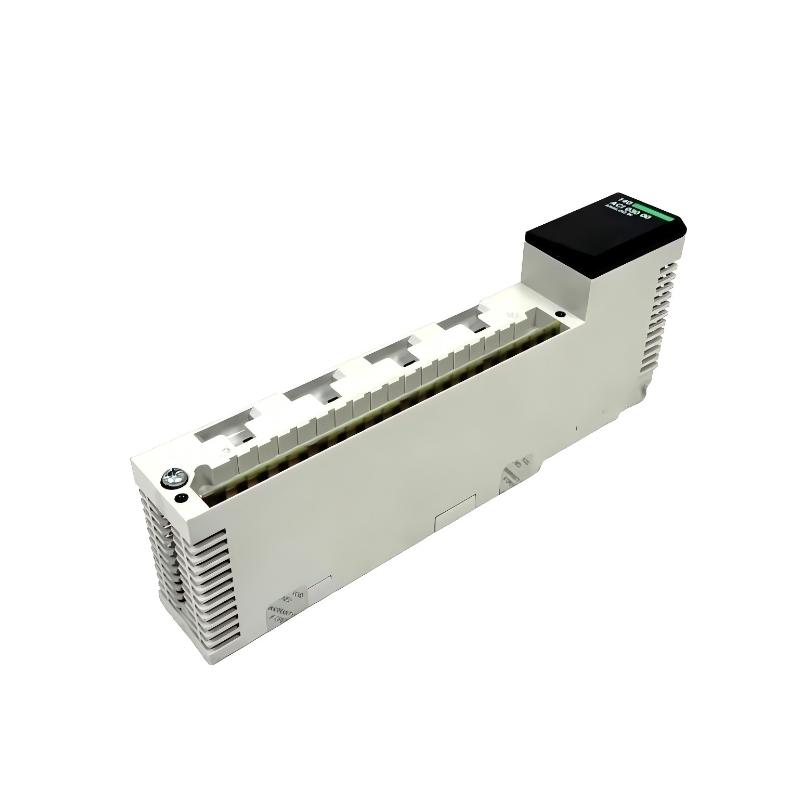
Troubleshooting the Schneider 140ACI03000C analog input module should begin with the complete analog signal path: field transmitter, wiring, terminal connections, module channel, rack communication, controller configuration, and engineering-unit scaling. An incorrect analog value does not automatically mean that the 140ACI03000C has failed.
Schneider 140ACI03000C Fault Diagnosis Overview
Analog input faults can appear as zero readings, unstable values, incorrect process values, channel diagnostic conditions, or differences between the field instrument and the PLC display. A systematic signal-path diagnosis helps identify whether the problem is in the field device, wiring, configuration, or input module.
Field Instrument
      |
      v
Signal Wiring
      |
      v
Terminal / Channel
      |
      v
140ACI03000C
      |
      v
Quantum Backplane
      |
      v
Controller
      |
      v
Engineering Value
The most useful diagnostic question is: At which point does the expected signal stop matching the actual system value?
Schneider 140ACI03000C Common Fault Symptoms
- Analog input remains at zero.
- Input value is higher or lower than expected.
- Analog value fluctuates unexpectedly.
- One channel behaves differently from other channels.
- Several channels show abnormal readings simultaneously.
- Controller reports an input or module diagnostic condition.
- Input value does not respond to process changes.
- PLC value differs from the field instrument indication.
- Analog signal becomes unstable after nearby equipment starts.
Common Causes of Schneider 140ACI03000C Faults
| Symptom | Possible Cause | Diagnostic Direction |
|---|---|---|
| Zero input | Broken wiring or incorrect channel connection | Trace the field signal path |
| Incorrect value | Scaling or configuration problem | Verify channel configuration and engineering units |
| Unstable value | Electrical interference or poor connection | Inspect shielding, routing, grounding, and terminals |
| One channel abnormal | Channel wiring or field-device issue | Compare with known-good channels where appropriate |
| Several channels abnormal | Common power, rack, or configuration issue | Check shared system conditions |
| No module communication | Rack, backplane, or configuration issue | Check module seating and controller diagnostics |
Schneider 140ACI03000C Troubleshooting Diagnostic Logic
Incorrect Analog Reading
          |
          v
Check Controller Diagnostics
          |
          v
Is Module Recognized?
      /          \
    No            Yes
    |              |
Check Rack       Check Channel
and Backplane    Configuration
                     |
                     v
              Check Field Signal
                     |
                     v
              Check Wiring
                     |
                     v
              Check Scaling
                     |
                     v
              Check Interference
                     |
                     v
              Evaluate Module
This sequence separates system-level faults from channel-level faults and prevents premature module replacement.
Schneider 140ACI03000C Testing and Fault Analysis
Check Module Recognition
First verify that the Quantum controller recognizes the 140ACI03000C correctly. If the entire module is unavailable, investigate rack position, backplane connections, configuration, and system diagnostics before troubleshooting individual field channels.
Check the Field Instrument
Determine whether the field transmitter or sensor is producing the expected signal. If the field instrument itself is not functioning correctly, replacing the input module will not correct the process measurement.
Check Signal Wiring
Inspect the complete circuit for loose terminals, broken conductors, incorrect channel assignments, damaged cables, poor connections, and unintended grounding conditions.
Expected Signal
      |
      v
Field Device
      |
      v
Cable
      |
      v
Terminal Connection
      |
      v
140ACI03000C Channel
      |
      v
Controller Value
Testing each stage helps identify where the signal is being lost or distorted.
Check Channel Configuration
If the electrical signal is correct but the controller displays an incorrect engineering value, review the channel configuration and scaling. A configuration mismatch can produce a stable but incorrect value, making the problem easy to overlook.
Check Analog Signal Stability
If the input fluctuates, investigate electrical noise, shielding, grounding, cable routing, nearby drives, contactors, motors, and other switching equipment. Compare the behavior with the field signal where possible.
Schneider 140ACI03000C Detailed Fault Isolation
A useful diagnostic method is to compare a suspected channel with a known-good channel only when the two channels have compatible signal characteristics and similar wiring arrangements.
Channel A:
Field Signal -> Normal
Controller Value -> Abnormal

Channel B:
Field Signal -> Normal
Controller Value -> Normal

Diagnostic Direction:
Investigate Channel A wiring,
configuration, or input path.
If multiple independent channels become abnormal at the same time, investigate common causes such as rack configuration, power conditions, backplane connections, grounding, or environmental interference.
Schneider 140ACI03000C Repair and Replacement Procedure
Before replacing the module, document the existing installation. This information is particularly important in an operating plant where the original configuration may contain application-specific channel assignments and scaling.
- Place the process in a safe maintenance state.
- Record the module position and channel assignments.
- Record relevant diagnostic information.
- Document field wiring before disconnection.
- Follow the approved procedure for removing the module.
- Inspect the rack and backplane connector.
- Install the correct replacement module.
- Reconnect the field wiring carefully.
- Verify channel configuration and scaling.
- Restore the controller configuration as required.
- Check every affected input channel.
- Perform a controlled process functional test.
Do not replace an analog input module solely because one process value is incorrect. First eliminate field-device, wiring, configuration, scaling, grounding, and interference problems.
Schneider 140ACI03000C Field Troubleshooting Case
Representative example: A process temperature value displayed by the PLC becomes unstable while the local instrument appears normal. The technician checks the module diagnostics and finds no obvious module-level failure.
Observed:
PLC temperature value fluctuates

Step 1:
Check field instrument
Result: Stable indication

Step 2:
Check module status
Result: Module recognized

Step 3:
Inspect wiring
Result: No obvious conductor damage

Step 4:
Inspect cable routing
Result: Analog cable runs near switching equipment

Step 5:
Improve routing / shielding arrangement
Result: Input stability improves
This is a representative diagnostic example rather than a manufacturer-specific failure case. It illustrates why unstable analog readings should be investigated as a complete signal-integrity problem instead of automatically being attributed to the input module.
Schneider 140ACI03000C Troubleshooting FAQ
Why does the 140ACI03000C show zero on an analog channel?
Possible causes include a missing field signal, broken wiring, incorrect channel assignment, configuration problems, or a problem with the field instrument. Trace the signal from the instrument toward the controller.
Why is the analog value stable but incorrect?
A stable but incorrect value can result from incorrect scaling, configuration, signal characteristics, wiring, or field-instrument calibration. Check the complete signal chain.
Why does only one channel have a problem?
A single-channel fault often points toward channel wiring, the connected field device, terminal connections, channel configuration, or a localized input-path problem. Compare with another compatible channel where appropriate.
Why do several analog channels become abnormal at the same time?
Multiple simultaneous faults may indicate a common system condition such as rack configuration, backplane connection, power, grounding, or environmental interference. Investigate common factors before replacing individual channels or modules.
Should I replace the 140ACI03000C when an analog value is wrong?
Not immediately. Verify the field instrument, wiring, channel configuration, scaling, grounding, and signal integrity first. Module replacement should follow evidence indicating a hardware problem.
Schneider 140ACI03000C Technical Summary
The Schneider 140ACI03000C analog input module is part of the signal interface between field instrumentation and a Modicon Quantum control system. Effective troubleshooting requires more than checking the module itself. Technicians should trace the complete signal path, verify field-device operation, inspect wiring and grounding, confirm channel configuration and scaling, and investigate electrical interference before concluding that the module requires replacement.