

ProductPRODUCT
Featured products
Contact Us
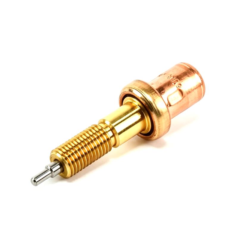
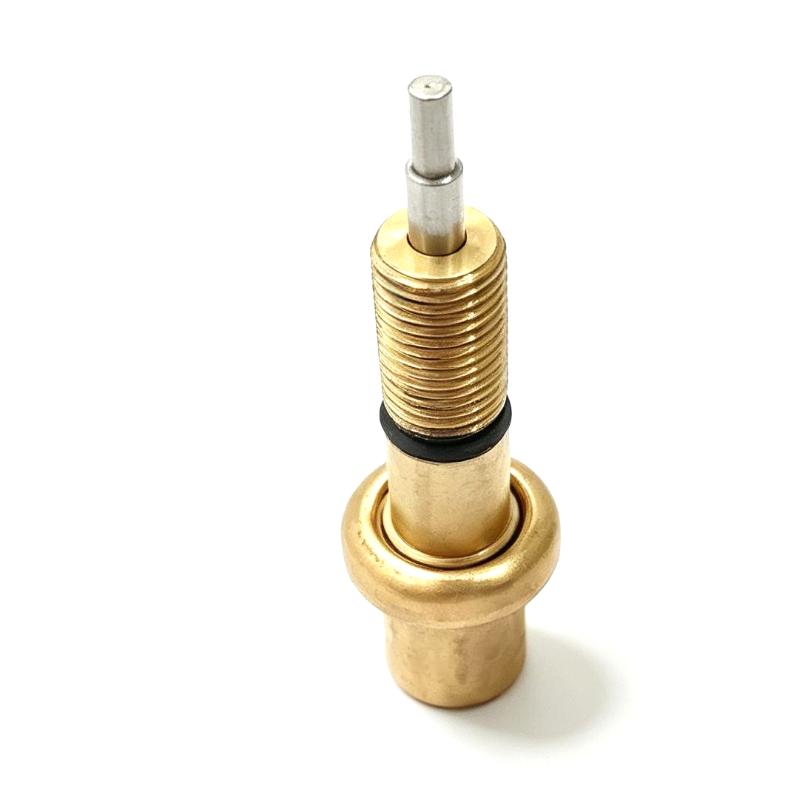
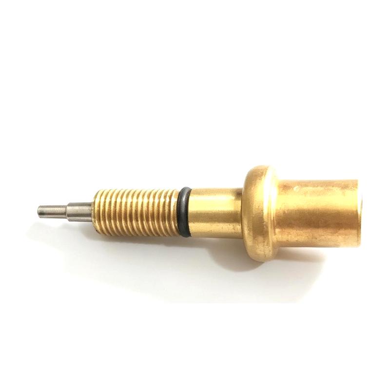
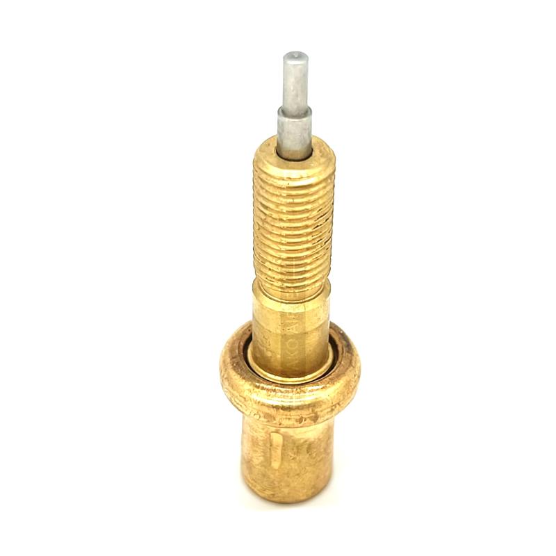
- Ingersoll Rand
- 23710842 23332588
- Thermostatic Valve Core
- USA
- 100 × 70 × 70 mm
- 2.29 kg
- Xiamen, China
- New & In Stock
- T/T, PayPal, Western Union
- 1 Year
- 1-3 Working Days
- DHL, UPS, TNT, FedEx and EMS.
- 24-Hour Service
- COO
- 4
Our advantage

Global Logistics
We have a 10-year logistics and express cooperation agreement, so our products can be shipped to any place in the world.

Brand new and original
Our products are imported in bulk from the place of origin. Because of the cooperative relationship, our products are all original and 100% new.

24-hour service
We provide 7*24 hours service to our customers. We will be there whenever you need us.

Price advantage
All our products are priced very favorably because we have our own warehouse and supply.
| Company Information | |||
| [email protected] | |||
| Mobile | +8615980777398 | ||
| +8615980777398 | |||
| 15980777398 |
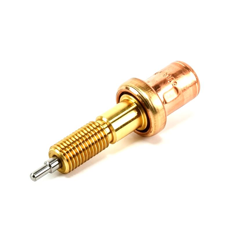
Product Overview
The Ingersoll Rand 23710842 / 23332588 Thermostatic Valve Core is a specialized replacement component designed for compatible industrial compressed-air and compressor systems. As a thermostatic control component, it plays an important role in regulating temperature-dependent fluid or oil flow within the associated equipment, helping maintain suitable operating conditions for the compressor and its lubrication or thermal-management circuit.
Thermostatic components are particularly important in compressor systems because temperature has a direct influence on lubrication performance, oil viscosity, component protection, and overall machine reliability. By responding to temperature conditions, a thermostatic valve assembly can help direct the appropriate flow path as the compressor transitions between operating and warmed-up conditions.
The Ingersoll Rand 23710842 / 23332588 is listed with dimensions of 100 × 70 × 70 mm and a weight of 2.29 kg. Its compact physical size makes it suitable for installation within industrial compressor equipment where thermal-control components must operate reliably in a confined mechanical environment.
This component is especially relevant for maintenance, overhaul, and replacement programs involving compatible Ingersoll Rand compressor equipment. When sourcing a replacement, the complete part-number relationship, equipment model, valve configuration, and existing component identification should be verified before installation.
Technical Specifications
| Parameter | Specification |
|---|---|
| Manufacturer | Ingersoll Rand |
| Part Number | 23710842 / 23332588 |
| Product Type | Thermostatic Valve Core |
| Component Category | Compressor Thermal-Control Component |
| Primary Function | Temperature-dependent flow regulation |
| Application | Industrial Compressor Systems |
| Installation | Compatible Ingersoll Rand Equipment |
| Dimensions | 100 × 70 × 70 mm |
| Weight | 2.29 kg |
| Replacement Type | Maintenance / Replacement Component |
| Typical Service | Compressor thermal and lubrication systems |
| Application Environment | Industrial equipment |
Specification Verification
The dimensions and weight stated above are based on the supplied product information:
- Dimensions: 100 × 70 × 70 mm
- Weight: 2.29 kg
Exact operating temperature, pressure rating, material composition, port configuration, valve response characteristics, and equipment compatibility should be confirmed against the applicable compressor configuration before installation.
What Is the Ingersoll Rand 23710842 / 23332588 Thermostatic Valve Core?
The 23710842 / 23332588 Thermostatic Valve Core is a temperature-responsive mechanical component used within compatible Ingersoll Rand compressor systems.
A thermostatic valve is designed to respond to changes in temperature. Depending on the operating condition, the valve can alter the internal flow path of the associated fluid, allowing the compressor’s thermal-management system to maintain an appropriate operating temperature.
In an industrial compressor, temperature control is not simply a matter of preventing overheating. Maintaining the correct temperature range can also help ensure proper lubricant characteristics and efficient operation of the compressor package.
The component can therefore be considered part of the compressor’s thermal-control chain:
Compressor → Temperature Change → Thermostatic Valve Response → Fluid Flow Adjustment → Temperature Regulation
The exact flow arrangement depends on the compressor design and the location of the thermostatic valve assembly.
Thermostatic Valve Working Principle
A thermostatic valve operates according to temperature-dependent mechanical behavior.
As the temperature of the controlled fluid changes, the thermostatic element responds by changing its position. This movement can alter the available flow path between different sections of the thermal-management circuit.
In a compressor system, this can allow the system to respond differently during:
- Cold startup
- Warm-up
- Normal operating temperature
- High-temperature operation
- Load changes
- Changing ambient conditions
During startup, lubricant or another controlled fluid may require a different flow path than during fully warmed operation. Once the system reaches its intended temperature range, the thermostatic mechanism can change position to support the normal cooling or circulation path.
This automatic response reduces the need for continuous external temperature control of the valve itself.
Role in Industrial Compressor Systems
The Ingersoll Rand 23710842 / 23332588 can contribute to maintaining thermal stability within a compatible compressor package.
Industrial compressors generate considerable heat during compression and mechanical operation. Lubricated compressor systems also depend on appropriate oil circulation and temperature management.
The thermostatic valve can therefore form part of the following functional sequence:
Compressor Operation → Heat Generation → Temperature Detection → Thermostatic Valve Movement → Flow Regulation → Thermal Stabilization
Stable thermal conditions can support:
- Lubrication performance
- Compressor reliability
- Component protection
- Stable operating conditions
- Reduced thermal stress
- Efficient compressor operation
A thermostatic valve should not be viewed as an isolated component. Its performance depends on the condition of the associated cooler, oil circuit, piping, seals, temperature-sensing element, and other compressor components.
Importance of Temperature Control in Compressors
Temperature control is a critical consideration in industrial compressor maintenance.
If the compressor operates at an excessively low temperature for extended periods, lubricant characteristics may not be optimal for the intended operating condition. In some applications, excessive cooling can also contribute to condensation-related problems.
At the other extreme, excessive operating temperature can accelerate lubricant degradation and increase thermal stress on internal components.
A correctly functioning thermostatic control system helps the compressor respond to changing thermal conditions.
For this reason, a relatively small component such as the 23710842 / 23332588 Thermostatic Valve Core can have an important role in the overall reliability of the compressor package.
Typical Applications
Industrial Air Compressors
The primary application area for a thermostatic valve core is compatible industrial compressor equipment.
Compressed-air systems are widely used in:
- Manufacturing plants
- Automotive production
- Machinery factories
- Food and beverage facilities
- Pharmaceutical manufacturing
- Chemical processing
- Packaging systems
- General industrial production
Maintaining stable compressor temperature helps support reliable compressed-air generation.
Manufacturing Facilities
Production plants often depend on compressors operating for long periods. A properly functioning thermal-control system helps prevent temperature-related interruptions.
Process Air Systems
Industrial process equipment may require a continuous and stable compressed-air supply. Thermal-control components can contribute to maintaining reliable compressor operation.
Maintenance and Overhaul Applications
The thermostatic valve core is also relevant when rebuilding or servicing compatible compressor assemblies.
Replacing worn thermal-control components during scheduled maintenance can help restore proper system operation.
Compressor Thermal Management
A typical compressor thermal-management circuit may include several components:
| Component | General Function |
|---|---|
| Compressor Element | Compresses the working gas |
| Lubrication System | Provides lubrication and cooling |
| Thermostatic Valve | Regulates temperature-dependent flow |
| Oil Cooler | Removes heat from lubricant |
| Temperature Sensor | Monitors system temperature |
| Filter | Removes contaminants from fluid |
| Piping | Transfers controlled fluid |
| Seals and Gaskets | Maintain system integrity |
The 23710842 / 23332588 Thermostatic Valve Core functions within this larger system.
A fault in any connected component can influence temperature behavior, meaning technicians should diagnose the complete thermal circuit rather than replacing the valve core without inspection.
Installation and Replacement Guidelines
Replacing a thermostatic valve core requires careful attention to the compressor’s mechanical and thermal system.
Confirm the Part Number
Before installation, verify:
- 23710842
- 23332588
- Existing valve assembly
- Compressor model
- Equipment serial information where applicable
- Valve configuration
- Replacement component dimensions
The two listed part numbers should be checked against the actual equipment configuration before ordering or installing a replacement.
Shut Down the Compressor
The compressor should be taken out of service according to the applicable maintenance procedure.
Before accessing the valve assembly, technicians should ensure that:
- Electrical power is isolated
- Stored pneumatic pressure is released
- Fluid pressure is safely relieved
- Hot surfaces have cooled
- Associated equipment cannot restart unexpectedly
Remove the Existing Valve Core
The existing thermostatic valve component should be removed carefully to avoid damaging surrounding housings, seals, threads, or mating surfaces.
Inspect the Valve Housing
Before installing the replacement, inspect the surrounding assembly for:
- Contamination
- Corrosion
- Mechanical damage
- Deposits
- Seal deterioration
- Abnormal wear
A new valve core may not correct a problem caused by a damaged valve housing or blocked fluid passage.
Install the Replacement
The replacement component should be installed according to the applicable equipment maintenance procedure.
Do not force the component into position. Improper installation can damage the valve or its mating components.
Restore the System
After installation:
- Reassemble the valve housing.
- Verify connections.
- Restore the required fluid circuit.
- Check for leakage.
- Restore electrical power.
- Start the compressor under controlled conditions.
- Monitor temperature behavior.
Troubleshooting the Thermostatic Valve Core
A thermostatic valve problem may appear as a temperature-related compressor fault rather than an obvious mechanical valve failure.
Compressor Operating Too Hot
Possible causes include:
- Thermostatic valve malfunction
- Restricted fluid flow
- Cooler contamination
- Inadequate cooling airflow
- High ambient temperature
- Incorrect fluid condition
- Sensor problems
- Other thermal-management faults
The thermostatic valve should be inspected as part of the complete cooling system.
Compressor Temperature Remains Too Low
A valve that does not respond correctly can potentially allow excessive cooling or an inappropriate flow path.
Other possible causes include:
- Incorrect valve operation
- Incorrect installation
- Low ambient temperature
- Excessive cooling airflow
- Sensor or monitoring problems
- Incorrect system configuration
Temperature Fluctuation
Repeated temperature changes may indicate:
- Valve instability
- Restricted passages
- Contamination
- Incorrect fluid circulation
- Sensor problems
- Cooler performance issues
Trend monitoring can help determine whether the temperature problem is continuous or intermittent.
Leakage Around the Valve Assembly
Leakage may be caused by:
- Damaged sealing components
- Incorrect installation
- Worn housing surfaces
- Loose connections
- Mechanical damage
Replacing the valve core alone may not resolve a sealing problem.
Maintenance Recommendations
Regular compressor maintenance should include inspection of temperature-control components.
Monitor Operating Temperature
Record temperature trends rather than relying only on individual readings.
A gradual change can provide an early warning of thermal-system deterioration.
Inspect the Cooling System
Check the associated cooler and airflow path for contamination or blockage.
Check Fluid Condition
The correct fluid type and condition are important for compressor reliability.
Inspect for Leakage
Look around the thermostatic valve assembly and associated connections for signs of fluid leakage.
Check Valve Response
If the compressor exhibits abnormal thermal behavior, the thermostatic mechanism should be inspected according to the applicable service procedure.
Maintain Clean Fluid Circuits
Contamination can interfere with mechanical valve operation and reduce the reliability of the thermal-control system.
Symptoms of a Potential Thermostatic Valve Problem
The following symptoms can justify further investigation of the thermostatic valve circuit:
- Abnormally high compressor temperature
- Abnormally low operating temperature
- Slow temperature stabilization
- Unusual temperature fluctuations
- Reduced compressor efficiency
- Repeated temperature alarms
- Lubricant-related operating problems
- Leakage around the valve assembly
- Abnormal thermal behavior after startup
These symptoms do not necessarily prove that the valve core is defective. Other components in the thermal-management system can create similar symptoms.
Replacement Part Selection
Selecting the correct replacement is important because thermostatic components may appear physically similar while having different operating characteristics.
When purchasing an Ingersoll Rand 23710842 / 23332588 Thermostatic Valve Core, technicians should verify:
- Complete part number
- Cross-reference information
- Compressor model
- Existing valve assembly
- Physical dimensions
- Operating requirements
- Connection arrangement
- Maintenance documentation
- Supplier part identification
The supplied physical specifications are:
100 × 70 × 70 mm
and:
2.29 kg
These specifications can also assist with warehouse management and replacement logistics.
Dimensions and Weight
The listed dimensions of the Ingersoll Rand 23710842 / 23332588 Thermostatic Valve Core are:
100 × 70 × 70 mm
The listed weight is:
2.29 kg
These physical characteristics are useful when planning:
- Spare-parts storage
- Shipping
- Inventory management
- Maintenance preparation
- Replacement handling
- Compressor service logistics
Physical dimensions alone should not be used as the sole method of determining compatibility.
Compatible Compressor System Components
The thermostatic valve core can work as part of a larger compressor maintenance system involving:
- Compressor air end
- Oil circulation system
- Oil cooler
- Oil filter
- Temperature sensor
- Pressure sensor
- Thermostatic valve assembly
- Seals and gaskets
- Hoses
- Piping
- Air/oil separator
- Control system
- Compressor controller
When a temperature-related fault occurs, technicians should evaluate these components together.
Recommended Related Ingersoll Rand Components
| Component Type | General Function |
|---|---|
| Oil Filter | Removes contaminants from compressor lubricant |
| Air-Oil Separator | Separates oil from compressed air |
| Breathing Filter | Supports clean air exchange within the system |
| Panel Air Filter | Protects equipment from airborne contamination |
| Thermostatic Valve Core | Provides temperature-dependent flow regulation |
| Cooler Assembly | Removes heat from the compressor fluid circuit |
| Temperature Sensor | Monitors operating temperature |
| Pressure Sensor | Monitors system pressure |
| Sealing Components | Prevent fluid leakage |
The exact compatibility of these components depends on the compressor model and configuration.
Preventive Maintenance Strategy
A proactive maintenance strategy can reduce the probability of unexpected compressor shutdowns.
Scheduled Inspection
Thermal-control components should be included in routine compressor inspections.
Temperature Trending
Monitoring temperature over time can identify gradual changes before they become severe.
Fluid and Filter Maintenance
Clean fluid and correctly maintained filtration reduce the possibility of contamination affecting valve operation.
Cooling-System Cleaning
Coolers and ventilation paths should remain clean and unobstructed.
Replacement During Overhaul
When a compressor undergoes major overhaul, thermostatic components can be evaluated for wear and replaced when required by the maintenance procedure.
Engineering Considerations
A thermostatic valve is a relatively small component, but its influence on compressor operation can be significant.
Engineers and maintenance technicians should consider:
Correct Part Identification
The complete 23710842 / 23332588 identification should be retained in maintenance records.
Thermal Conditions
Ambient temperature and compressor loading affect the thermal behavior of the system.
Fluid Characteristics
The correct lubricant or controlled fluid must be used according to the compressor requirements.
Cleanliness
Contaminants can interfere with valve movement and fluid circulation.
Mechanical Condition
The valve housing, seals, connections, and associated components should be inspected whenever the valve core is replaced.
Commissioning
After replacement, temperature behavior should be monitored carefully during startup and normal operation.
Key Advantages
The Ingersoll Rand 23710842 / 23332588 Thermostatic Valve Core offers several important benefits when correctly matched to compatible compressor equipment:
- Supports automatic temperature-dependent flow regulation
- Contributes to compressor thermal stability
- Supports proper lubrication-system operation
- Helps maintain appropriate operating conditions
- Suitable for industrial compressor maintenance
- Compact 100 × 70 × 70 mm design
- Listed weight of 2.29 kg
- Useful as a replacement component during compressor service
- Supports preventive maintenance and equipment refurbishment
- Can contribute to reliable long-term compressor operation
Technical FAQs
What is the Ingersoll Rand 23710842 / 23332588?
It is a Thermostatic Valve Core intended for compatible Ingersoll Rand compressor equipment.
What does a thermostatic valve core do?
It responds to temperature conditions and helps regulate the flow path of the associated fluid within the compressor’s thermal-management circuit.
Why is a thermostatic valve important in a compressor?
Proper temperature regulation can help maintain suitable lubrication and operating conditions while reducing the risk of excessive thermal stress.
What are the dimensions of the 23710842 / 23332588?
The listed dimensions are 100 × 70 × 70 mm.
How much does the component weigh?
The listed weight is 2.29 kg.
Can the 23710842 and 23332588 be treated as interchangeable?
They are provided together as the product identification for this thermostatic valve core, but compatibility should still be confirmed against the specific compressor and valve assembly before installation.
What can cause a compressor to run too hot?
Possible causes include thermostatic valve problems, restricted fluid circulation, cooler contamination, inadequate cooling, high ambient temperature, fluid problems, sensor issues, or other compressor-system faults.
Can a dirty cooler cause symptoms similar to a valve problem?
Yes. Restricted heat transfer can produce abnormal compressor temperatures even when the thermostatic valve itself is functioning correctly.
What should be checked before replacing the valve core?
Verify the complete part number, compressor model, existing valve assembly, dimensions, connection arrangement, and applicable maintenance requirements.
Is the valve core a general-purpose industrial valve?
No. It should be treated as a specialized compressor component and should only be installed where compatibility has been confirmed.
Conclusion
The Ingersoll Rand 23710842 / 23332588 Thermostatic Valve Core is an important thermal-management component for compatible industrial compressor systems. By responding to temperature conditions and controlling the associated fluid flow path, the thermostatic mechanism can contribute to stable compressor temperature, proper lubrication conditions, and reliable equipment operation.
The component has supplied dimensions of 100 × 70 × 70 mm and a listed weight of 2.29 kg, making these specifications useful for spare-parts identification, inventory management, shipping, and maintenance planning.
For replacement work, technicians should verify the complete 23710842 / 23332588 identification together with the compressor model and existing valve assembly. Proper installation, clean fluid circuits, appropriate cooling performance, correct sealing, and post-installation temperature monitoring are essential for dependable operation.
When used as part of a properly maintained compressor thermal-management system, the Ingersoll Rand 23710842 / 23332588 Thermostatic Valve Core can support stable operating temperatures and contribute to the long-term reliability of industrial compressed-air equipment.