

ProductPRODUCT
Featured products
Contact Us
- Ingersoll Rand
- 15483514 24121212
- Separator
- USA
- 205 × 45 × 95 mm
- 0.91 kg
- Xiamen, China
- New & In Stock
- T/T, PayPal, Western Union
- 1 Year
- 1-3 Working Days
- DHL, UPS, TNT, FedEx and EMS.
- 24-Hour Service
- COO
- 3
Our advantage

Global Logistics
We have a 10-year logistics and express cooperation agreement, so our products can be shipped to any place in the world.

Brand new and original
Our products are imported in bulk from the place of origin. Because of the cooperative relationship, our products are all original and 100% new.

24-hour service
We provide 7*24 hours service to our customers. We will be there whenever you need us.

Price advantage
All our products are priced very favorably because we have our own warehouse and supply.
| Company Information | |||
| [email protected] | |||
| Mobile | +8615980777398 | ||
| +8615980777398 | |||
| 15980777398 |
Product Overview
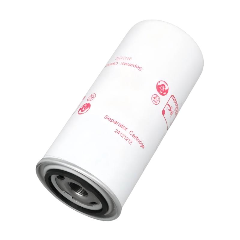
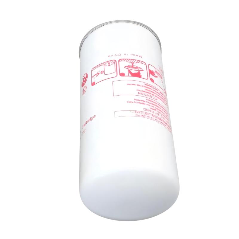
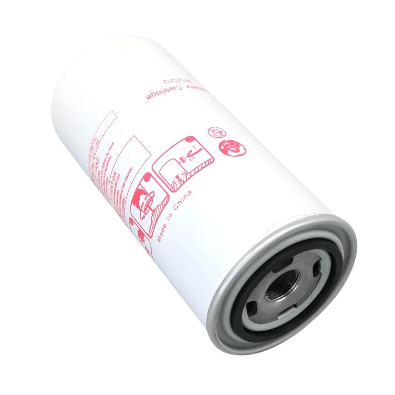
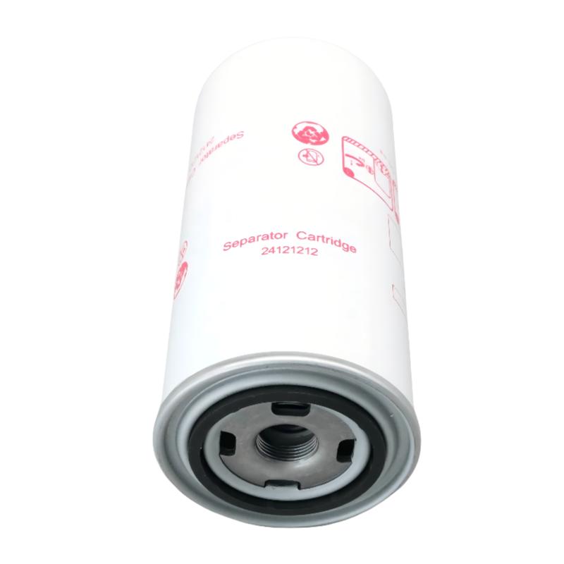
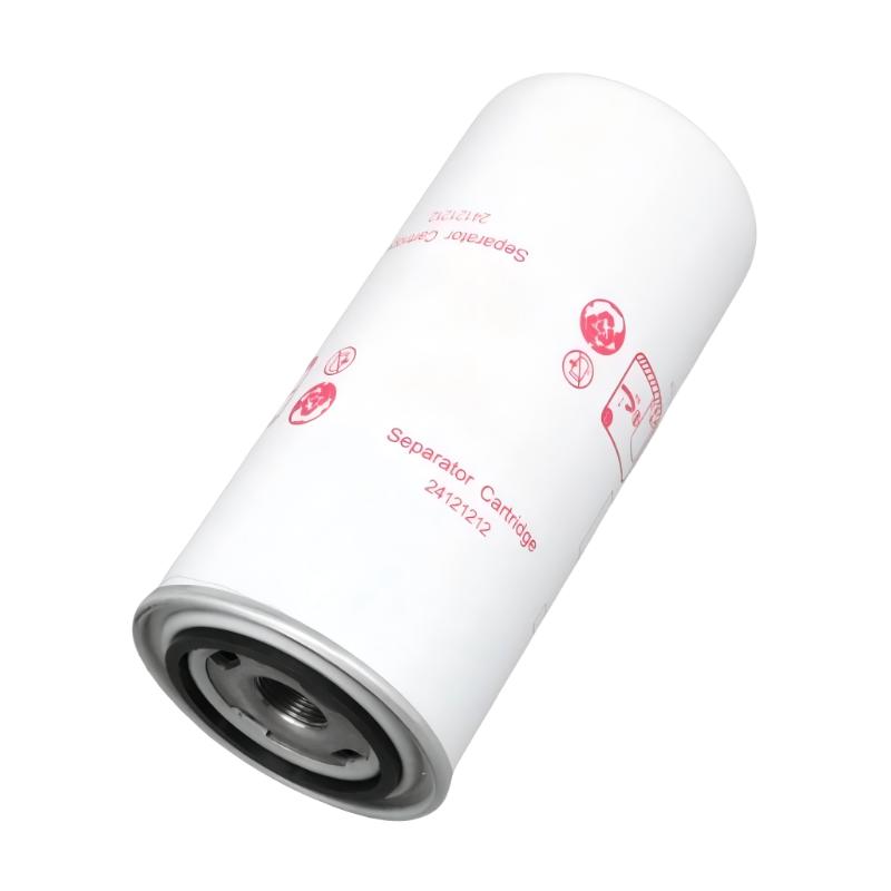
The Ingersoll Rand 15483514 24121212 Separator is an industrial compressor separation component identified by the part numbers 15483514 and 24121212. In oil-injected compressor systems, a separator assembly is used to separate oil carried in the compressed-air stream, allowing recovered oil to return to the lubrication circuit while reducing the amount of oil leaving with the compressed air.
During compression, air and lubricating oil may become mixed as the oil supports lubrication, cooling, and sealing within the compressor. Before the compressed air enters the downstream delivery system, the separation stage removes most of the entrained oil. The effectiveness of this process depends on the separator’s construction, the compressor’s operating conditions, airflow, and the condition of the associated seals and return components.
For maintenance teams, correct identification of the Ingersoll Rand 15483514 24121212 Separator is important when preparing a compressor service or replacing a separator that has reached its service limit. A separator should not be selected by appearance or dimensions alone because different elements may have different flow capacities, pressure characteristics, mounting arrangements, and separation performance.
Separator condition can influence both compressed-air quality and compressor operation. A restricted element may increase pressure drop, while damaged sealing surfaces or an incorrectly installed separator can allow excessive oil carryover. During replacement, technicians should inspect the associated housing, seals, and oil-return path to help identify conditions that could affect the new component.
Technical Specifications
| Parameter | Specification |
|---|---|
| Manufacturer | Ingersoll Rand |
| Product Model | 15483514 |
| Additional Part Number | 24121212 |
| Product Type | Separator |
| Product Category | Industrial Compressor Separation Components |
| Primary Function | Separation of entrained oil from compressed air |
| Application | Compatible oil-injected compressor systems |
| Separation Medium | Separator element or assembly, depending on the product configuration |
| System Integration | Compressor air/oil separation system |
| Operating Medium | Compressed air containing entrained oil |
| Oil Recovery | Supports oil return where incorporated into the compressor’s separation arrangement |
| Installation Type | Equipment-specific separator housing or mounting assembly |
| Maintenance Approach | Inspection and scheduled replacement |
| Replacement Criteria | Applicable service interval, pressure-drop condition, and equipment requirements |
| Dimensions | 205 × 45 × 95 mm |
| Weight | 0.91 kg |
Product Features
- Oil Separation: Supports the removal of entrained oil from compressed air in compatible compressor systems.
- Part Identification: The 15483514 and 24121212 designations provide references for spare-parts purchasing and maintenance records.
- Compressed-Air Treatment: Helps reduce oil carryover before compressed air proceeds to downstream equipment.
- Lubricant Recovery Support: Works with the associated oil-return arrangement where the compressor design provides one.
- Maintenance Replacement: Provides a specific component reference for scheduled separator servicing.
- Housing Interface Requirements: Correct installation and sealing are necessary to prevent unfiltered bypass and external leakage.
- Operating Condition Monitoring: Separator condition can be assessed alongside pressure drop, oil carryover, and compressor operating data.
- System-Level Maintenance: Replacement provides an opportunity to inspect the separator housing, seals, and oil-return components.
Working Principle
The Ingersoll Rand 15483514 24121212 Separator operates within the compressor’s air/oil separation stage. In an oil-injected compressor, compressed air leaving the compression process contains entrained lubricant. The separator assembly uses its separation medium and internal flow arrangement to remove oil from the air stream, allowing the separated oil to collect for recovery where the system design provides an oil-return path.
As the air/oil mixture passes through the separator, oil droplets are retained or coalesced according to the separator’s construction. The recovered oil is directed toward the designated collection or return arrangement, while the separated air continues toward the compressor outlet. The separator’s exact internal design and performance characteristics depend on the specific equipment configuration.
Over time, accumulated contamination, aging of the separation medium, or changes in operating conditions may affect pressure drop and oil carryover. Incorrect installation, damaged seals, or a restricted oil-return line can also cause abnormal separator performance. When troubleshooting, technicians should evaluate the separator together with the housing, oil-return components, lubricant condition, and compressor operating parameters.
Typical separation path:
Compression Stage → Air/Oil Mixture → Separator Assembly → Separated Compressed Air → Downstream Air System
Recovered Oil → Oil Collection or Return Path → Compressor Lubrication Circuit
The separator does not replace downstream air-treatment equipment where a specific air-quality requirement applies. Its role is to perform the separation function assigned to it within the compressor’s own air/oil management system.
Role in an Industrial Compressor Air/Oil Separation Architecture
Within an oil-injected compressor, the separator forms part of the system that manages the relationship between compressed air and circulating lubricant. It works alongside the compression stage, separator housing, oil-return arrangement, and downstream air circuit. Correct operation depends on the condition of the complete assembly rather than the separator element alone.
| System Component | Function | Relationship to the Separator |
|---|---|---|
| Compressor Air End | Compresses incoming air and introduces oil where required by the design | Produces the air/oil mixture that enters the separation stage |
| Separator | Removes entrained oil from compressed air | Performs the main separation function |
| Separator Housing | Holds the separator and directs internal flow | Provides the mounting, sealing, and flow arrangement |
| Oil Collection Area | Collects separated oil where incorporated into the assembly | Receives recovered lubricant for return or circulation |
| Oil Return Line | Returns recovered oil where the system design includes this path | Carries separated oil back to the designated lubrication point |
| Lubricating Oil Circuit | Supplies oil for lubrication, cooling, or sealing functions | Receives recovered oil as part of the system’s circulation arrangement |
| Minimum Pressure or Check Valve | Controls pressure or flow where fitted | Supports the compressor’s specified operating arrangement |
| Aftercooler | Reduces compressed-air temperature downstream of compression | Receives compressed air after the relevant upstream treatment stages |
| Oil Carryover or Pressure Monitoring | Indicates relevant operating conditions where instrumentation is installed | Helps identify possible separator or lubrication-system problems |
Industrial Applications
| Application Area | Typical Use | Relevance of the Separator |
|---|---|---|
| Industrial Air Compressors | Separation of oil from compressed air | Supports the air/oil management process in compatible oil-injected systems |
| Compressor Preventive Maintenance | Scheduled replacement of separation components | Provides a specific part reference for service planning |
| Manufacturing Plant Air Systems | Supplying compressed air to production equipment | Helps reduce oil carried from the compressor into downstream piping |
| Compressor Overhaul | Renewal of service components during refurbishment | Allows the separation assembly and associated return path to be inspected |
| Industrial Utility Systems | Maintaining compressor packages used for plant services | Supports separation performance under the intended operating conditions |
| Compressor Performance Troubleshooting | Investigation of excessive oil carryover or abnormal pressure drop | Provides one component to inspect during system-level diagnosis |
| Maintenance Workshop Operations | Preparation of parts for planned compressor servicing | Supports component identification and consumable tracking |
| Spare Parts Management | Inventory control for compressor separation components | Helps distinguish the required separator from air filters and oil filters |
Installation and Maintenance
- Verify the separator identification: Confirm the 15483514 and 24121212 part numbers against the installed component and the equipment’s maintenance records before replacement.
- Review the service procedure: Check the applicable compressor maintenance instructions for the correct separator type, installation arrangement, replacement interval, and required sealing components.
- Isolate the compressor: Stop the equipment and follow the prescribed electrical isolation and pressure-release procedures before opening the separator assembly.
- Allow the system to cool: Ensure that the separator housing and associated components are at a safe temperature for maintenance before handling them.
- Prepare the work area: Use appropriate oil collection equipment and keep dust, debris, and cleaning materials away from the open compressed-air and lubrication circuits.
- Inspect the separator housing: Check the housing, cover, and accessible internal surfaces for contamination, damage, corrosion, or signs of abnormal operating conditions.
- Remove the existing separator carefully: Follow the specified removal procedure and note the installed orientation, sealing arrangement, and any associated connections.
- Inspect seals and contact surfaces: Check the relevant gaskets, O-rings, sealing faces, and mounting interfaces for wear, damage, contamination, or deformation.
- Check the oil-return arrangement: Where applicable, inspect the oil-return line and associated passages for obstruction, damage, or other conditions that could affect recovered-oil flow.
- Install the replacement separator: Confirm the part identification and orientation, fit the specified sealing components, and follow the prescribed tightening procedure without applying excessive force.
- Perform operational checks: Restore the system according to the approved startup procedure and check for oil leakage, abnormal pressure drop, unusual operating conditions, or excessive oil carryover.
- Document the maintenance: Record the separator part numbers, replacement date, operating hours where applicable, observed condition, and post-maintenance inspection results.
Related Components
| Component | Function | Relationship to the Separator |
|---|---|---|
| Ingersoll Rand Compressor Oil Filter | Removes contaminants from circulating lubricating oil | Performs oil filtration rather than air/oil separation |
| Ingersoll Rand Compressor Air Filter | Filters incoming ambient air | Protects the intake path and is separate from the separator’s function |
| Separator Housing | Holds and seals the separator assembly | Provides the mechanical and flow interface |
| Separator Gasket or O-Ring | Seals the relevant housing interfaces | Helps prevent leakage and unwanted bypass |
| Oil Return Line | Returns separated oil where fitted | Supports recovery of lubricant from the separation stage |
| Compressor Lubricating Oil | Lubricates and may cool internal components | Forms part of the air/oil mixture processed by the separation system |
| Minimum Pressure Valve | Maintains required pressure conditions where fitted | Supports the compressor’s specified pressure and flow arrangement |
| Aftercooler | Cools compressed air after compression | Provides downstream thermal treatment |
| Compressed-Air Dryer | Reduces moisture in compressed air | Performs a separate downstream air-treatment function |
Recommended Related Models
| Model or Product Category | Product Type | Relationship |
|---|---|---|
| Ingersoll Rand 15483514 24121212 | Separator | Specified product identification for replacement and inventory purposes |
| Ingersoll Rand Compressor Separators | Air/Oil Separation Components | Related product category for compatible compressor configurations |
| Ingersoll Rand Compressor Oil Filters | Lubrication Filtration Components | Related maintenance category, but not interchangeable with a separator |
| Ingersoll Rand Compressor Air Filters | Intake Filtration Components | Related filtration category for incoming air |
| Ingersoll Rand Separator Housing Components | Mounting and Sealing Components | Related components that support separator installation |
| Ingersoll Rand Oil Return Components | Lubrication-System Components | Related parts for systems that return separated oil |
| Ingersoll Rand Compressor Maintenance Kits | Maintenance Consumable Kits | May contain separators and other service parts depending on the kit configuration |
| Industrial Compressed-Air Aftercoolers | Air Treatment Components | Related downstream equipment for reducing compressed-air temperature |
Key Advantages
- Oil Carryover Control: Supports the separation of entrained oil from compressed air in compatible compressor systems.
- Lubricant Recovery Support: Works with the designated oil-return arrangement where provided.
- Accurate Part Identification: The two part numbers support maintenance planning and inventory management.
- Preventive Maintenance Integration: Provides a specific component reference for scheduled separator replacement.
- System-Level Troubleshooting: Separator condition can be assessed alongside pressure drop, oil return, and sealing performance.
- Maintenance Traceability: Replacement records help document separator service history and operating observations.
Technical FAQs
What is the function of the Ingersoll Rand 15483514 24121212 Separator?
It is identified as a compressor separator component. In an oil-injected compressor application, a separator removes entrained oil from compressed air and supports oil recovery through the system’s designated return arrangement.
Is this separator interchangeable with an Ingersoll Rand oil filter?
No. An oil filter removes contaminants from lubricating oil, whereas a separator removes oil carried in compressed air. The two components have different functions, flow paths, and installation requirements.
What can cause excessive oil carryover after separator replacement?
Possible causes include an incorrectly installed separator, damaged seals, a blocked or restricted oil-return path, incorrect component selection, or other compressor operating problems. Check the complete separation system before determining the cause.
When should the separator be replaced?
The replacement interval depends on the compressor’s maintenance requirements, operating hours, operating conditions, and any applicable pressure-drop or oil-carryover criteria. Follow the service schedule for the intended equipment rather than relying on a universal interval.