

ProductPRODUCT
Featured products
Contact Us
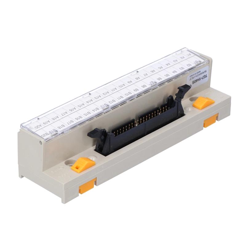
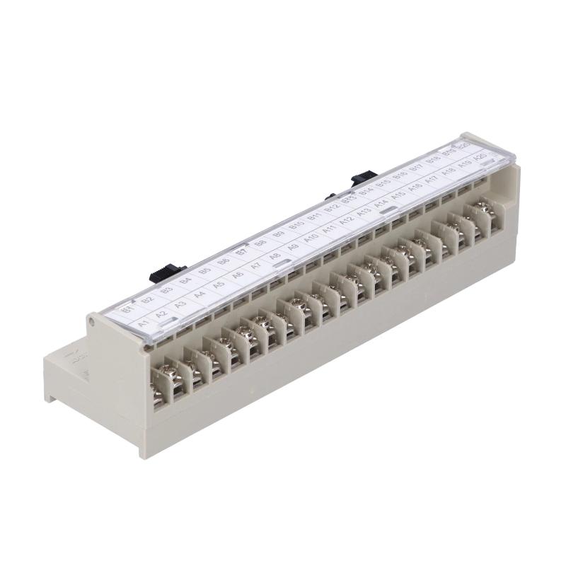
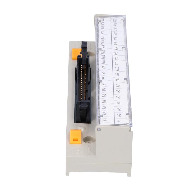
- Honeywell
- TG7-1H40S
- Smart Link 40 Pin Terminal Strip Board
- USA
- 40-Pin Connector
- 0.08 kg
- Xiamen, China
- New & In Stock
- T/T, PayPal, Western Union
- 1 Year
- 1-3 Working Days
- DHL, UPS, TNT, FedEx and EMS.
- 24-Hour Service
- COO
- 7
Our advantage

Global Logistics
We have a 10-year logistics and express cooperation agreement, so our products can be shipped to any place in the world.

Brand new and original
Our products are imported in bulk from the place of origin. Because of the cooperative relationship, our products are all original and 100% new.

24-hour service
We provide 7*24 hours service to our customers. We will be there whenever you need us.

Price advantage
All our products are priced very favorably because we have our own warehouse and supply.
| Company Information | |||
| [email protected] | |||
| Mobile | +8615980777398 | ||
| +8615980777398 | |||
| 15980777398 |
Product Overview
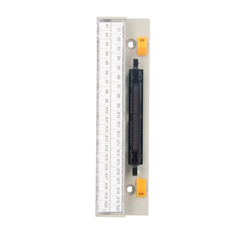
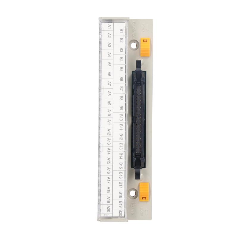
The Honeywell TG7-1H40S is a 40-pin Smart Link Terminal Strip Board used to simplify field wiring between compatible PLC I/O modules and external equipment. It converts a multi-pin I/O connection into an accessible terminal arrangement, allowing individual field wires to be connected and maintained without terminating every signal directly at the PLC connector.
In conventional PLC installations, I/O modules often use multi-pin connectors to accommodate a large number of digital or other control signals. Connecting individual field wires directly to these connectors can make cabinet wiring complicated, particularly when several channels need to be connected or replaced. The TG7-1H40S provides a more practical termination arrangement by separating the PLC-side connector interface from the field wiring terminals.
For example, in a manufacturing line with multiple sensors, switches, and actuators, the PLC I/O module may use a 40-pin interface to handle numerous signal connections. The TG7-1H40S allows these connections to be routed through a terminal board, where technicians can identify, connect, and inspect individual wiring points more conveniently.
The board uses a 40-pin connector and a terminal arrangement identified by the A1–A20 and B1–B20 numbering scheme. This provides an organized connection layout for the corresponding I/O signals. A compatible connection cable links the terminal board to the PLC module, keeping the field wiring separate from the module’s direct connector interface.
One practical advantage is easier maintenance. When a field signal needs to be checked, technicians can access the corresponding terminal instead of repeatedly disconnecting the PLC’s multi-pin connector. This is particularly useful in control cabinets where wiring density is high and individual signal identification matters during troubleshooting.
The TG7-1H40S is a passive wiring accessory. It does not perform signal conversion, PLC logic processing, or independent communication. Its role is to provide an organized electrical termination point between compatible PLC hardware and external wiring.
Technical Specifications
| Parameter | Specification |
|---|---|
| Manufacturer | Honeywell |
| Model | TG7-1H40S |
| Product Type | Smart Link 40 Pin Terminal Strip Board |
| Product Category | Smart Link Terminal Board |
| Connection Type | 40-Pin Connector |
| Terminal Arrangement | A1–A20 / B1–B20 |
| Rated Current | 1 A |
| Rated Voltage | AC/DC 125 V |
| Applicable Wire | Up to 1.25 mm² |
| Terminal Screw | M3 × 10L |
| Screw Torque | 1.2 N·m |
| Insulation Resistance | 100 MΩ (DC 500 V) |
| Cable Connection | Compatible 40-Pin Smart Link Cable |
| Weight | 0.08 kg |
Product Features
- 40-Pin Connection: Provides a multi-channel interface for compatible PLC I/O modules.
- Individual Terminal Access: Separates field wiring connections into accessible termination points.
- Organized Signal Layout: Uses A1–A20 and B1–B20 terminal identification for wiring organization.
- Simplified Cabinet Wiring: Reduces the need to terminate multiple field wires directly at the PLC connector.
- Compatible Smart Link Cabling: Works with the appropriate 40-pin connection cable for the supported I/O hardware.
- Convenient Troubleshooting: Allows technicians to inspect individual terminal connections during maintenance.
- Screw-Type Termination: Uses M3 terminal screws for field wire connections.
- Compact Terminal Arrangement: Consolidates multiple I/O connections into a single terminal board.
- Passive Electrical Interface: Does not require independent power or software configuration.
- Modular Wiring Arrangement: Separates PLC-side connections from field-side wiring for easier cabinet organization.
Product Working Principle
The TG7-1H40S works as an intermediate wiring interface between a PLC’s multi-pin I/O connector and the individual field wiring terminals.
The PLC module generates or receives electrical signals through its 40-pin connector. Instead of connecting the field wiring directly to that connector, a compatible cable links the PLC module to the TG7-1H40S terminal board.
The basic connection arrangement is:
PLC I/O Module → 40-Pin Connection Cable → TG7-1H40S Terminal Board → Individual Field Wires → Sensors / Actuators
Inside the terminal board, the connector pins are routed to their corresponding terminal positions. Each terminal provides an accessible point for connecting the associated field conductor.
For an input application, signals from devices such as limit switches, proximity sensors, and other compatible field instruments travel through the terminal board and cable to the PLC input channels.
For an output application, the PLC output signals pass through the corresponding connections to external devices such as relays, indicator lamps, and other compatible loads.
The terminal board does not amplify, isolate, or convert these signals. It maintains the electrical connection between the PLC connector and the external wiring according to the assigned pin configuration.
Correct pin mapping is therefore essential. Before installation, technicians should compare the PLC module’s wiring diagram with the terminal board connection layout to ensure that every field signal reaches the intended channel.
Role in PLC I/O Control System Architecture
The TG7-1H40S occupies the field wiring interface layer of a PLC control system. It sits between the I/O module and the external terminal wiring, providing a more accessible connection arrangement for cabinet installation and maintenance.
A typical arrangement is:
PLC CPU → I/O Module → 40-Pin Interface → Smart Link Cable → TG7-1H40S → Field Wiring → Industrial Devices
| System Component | Function |
|---|---|
| PLC CPU | Executes the control program and manages I/O operations |
| Digital Input Module | Receives signals from switches and field sensors |
| Digital Output Module | Controls external devices through PLC output channels |
| TG7-1H40S | Provides a 40-pin terminal wiring interface |
| Smart Link Connection Cable | Connects the PLC I/O connector to the terminal board |
| Field Terminal Wiring | Routes individual signals to and from the terminal board |
| Proximity Sensors | Detect the presence or position of objects |
| Limit Switches | Provide equipment position and movement status |
| Relays and Contactors | Switch external electrical loads |
| Indicator Lamps | Display equipment and process operating conditions |
The terminal board does not replace the PLC I/O module. The I/O module remains responsible for signal acquisition and output control, while the TG7-1H40S provides the physical wiring interface.
Industrial Applications
The TG7-1H40S is suitable for PLC installations where a multi-pin I/O connector needs to be converted into an organized field wiring arrangement.
| Industrial Application | Typical Use |
|---|---|
| Industrial Manufacturing | Connecting production-line sensors and actuators to PLC I/O modules |
| Packaging Machinery | Organizing wiring for photoelectric sensors, switches, and output devices |
| Automotive Production | Providing accessible termination points for machine control signals |
| Material Handling | Connecting conveyor sensors, limit switches, and motor control signals |
| Food Processing | Simplifying wiring arrangements in automated processing equipment |
| Chemical Processing | Organizing field signal connections inside PLC control cabinets |
| Water Treatment | Connecting pump status signals, level switches, and valve control circuits |
| Power Generation | Providing structured I/O wiring interfaces in auxiliary control systems |
| Compressor Control Systems | Organizing equipment status and control signal connections |
| Assembly Automation | Simplifying wiring between PLC modules and distributed machine components |
Installation and Maintenance
- Verify the Model: Confirm that the terminal board is TG7-1H40S and that the 40-pin configuration matches the intended PLC I/O interface.
- Check Module Compatibility: Identify the exact PLC I/O module and verify that it supports the TG7-1H40S connection arrangement.
- Select the Correct Cable: Use the compatible 40-pin Smart Link cable with the correct connector configuration and cable length.
- Inspect the Connector: Check the 40-pin interface for bent contacts, contamination, or mechanical damage.
- Check Terminal Identification: Review the A1–A20 and B1–B20 terminal arrangement before connecting field conductors.
- Prepare the Field Wires: Select conductors within the specified wire-size range and remove insulation to the appropriate termination length.
- Connect the Field Wiring: Secure each conductor to its assigned terminal according to the PLC wiring diagram.
- Apply Correct Screw Torque: Tighten terminal screws according to the specified torque to avoid loose connections or damage to the terminal assembly.
- Verify Pin Mapping: Check continuity between the PLC connector and the corresponding terminal positions before energizing the system.
- Inspect Cable Routing: Keep the Smart Link cable properly routed and avoid excessive bending or mechanical stress on the connectors.
- Perform Signal Testing: Test the connected input and output channels individually to confirm correct signal transmission.
- Record Wiring Information: Document the terminal assignments, connected devices, cable identification, and maintenance results for future troubleshooting.
During maintenance, loose terminal screws and incorrect pin assignments are common issues worth checking first. If a signal is missing, technicians should inspect the field device, terminal connection, Smart Link cable, and PLC I/O channel separately.
Compatible System Components
| Component | Function |
|---|---|
| XTB-40H | Smart Link terminal board designation associated with TG7-1H40S |
| C40HH-05SB-XBI | 40-pin Smart Link cable, 0.5 m |
| C40HH-10SB-XBI | 40-pin Smart Link cable, 1 m |
| C40HH-05SB-XBE | Smart Link cable for compatible expansion modules |
| C40HH-10SB-XBE | Smart Link cable for compatible expansion modules |
| XBM-DN32H | PLC main unit with a compatible 40-pin I/O connection |
| XBM-DP32H | PLC main unit with a compatible 40-pin I/O connection |
| XEM-DN32H | PLC main unit with a compatible Smart Link connection |
| XEM-DP32H | PLC main unit with a compatible Smart Link connection |
| XBE-DC32A | Expansion digital input module |
| XBE-TN32A | Expansion transistor output module |
| XBE-TP32A | Expansion transistor output module |
| XBE-DN32A | Expansion digital I/O module |
Recommended Related Models
| Model / Product | Product Type | Typical Application |
|---|---|---|
| TG7-1H40CA | 40-Pin Smart Link Terminal Board | Alternative terminal board with additional common connections |
| XTB-40H | 40-Pin Smart Link Terminal Board | PLC I/O field wiring interface |
| C40HH-05SB-XBI | Smart Link Connection Cable | Short-distance main unit connection |
| C40HH-10SB-XBI | Smart Link Connection Cable | Main unit connection with 1 m cable length |
| C40HH-10SB-XBE | Smart Link Connection Cable | Expansion module connection |
| R32C-NS5A-40P | 40-Pin Relay Board | Relay output wiring interface |
Key Advantages
- 40-pin interface for compatible PLC I/O modules.
- Organized terminal arrangement for field wiring.
- Simplifies connection of multiple field signals.
- Accessible terminals for inspection and troubleshooting.
- Compatible with dedicated Smart Link connection cables.
- Screw-type field wiring connections.
- Passive interface without independent power requirements.
- Suitable for high-density PLC control cabinets.
Technical FAQs
1. What is the purpose of the Honeywell TG7-1H40S?
The TG7-1H40S is a 40-pin Smart Link Terminal Board. It provides an accessible terminal connection arrangement between a compatible PLC I/O module and external field wiring, making cabinet wiring and maintenance easier.
2. How many terminal connection points does the TG7-1H40S provide?
Its terminal arrangement is identified by two groups, A1–A20 and B1–B20, corresponding to the 40-pin interface. The actual signal assignment must be checked against the wiring diagram of the connected PLC module.
3. Which cable is used with the TG7-1H40S?
Compatible Smart Link connection cables depend on the PLC unit and installation position. The C40HH-05SB-XBI and C40HH-10SB-XBI are listed for compatible main-unit connections, while C40HH series XBE cables are used for supported expansion-module connections.
4. Does the TG7-1H40S convert or amplify PLC signals?
No. It is a passive terminal wiring interface. It routes the electrical connections between the 40-pin connector and individual terminals without independently converting, amplifying, or processing the signals.