

ProductPRODUCT
Featured products
Contact Us
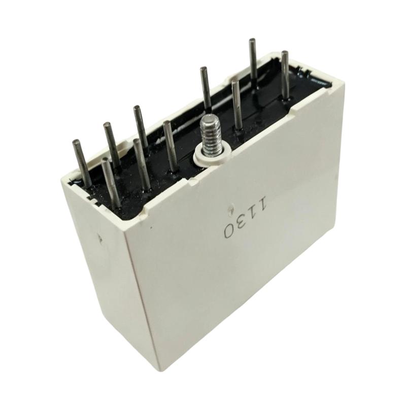
- Honeywell
- 51190523-125
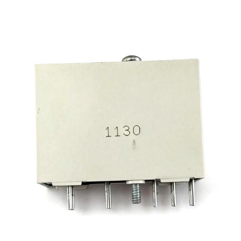
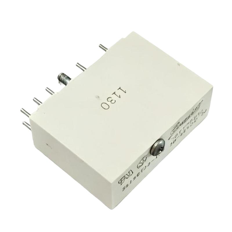
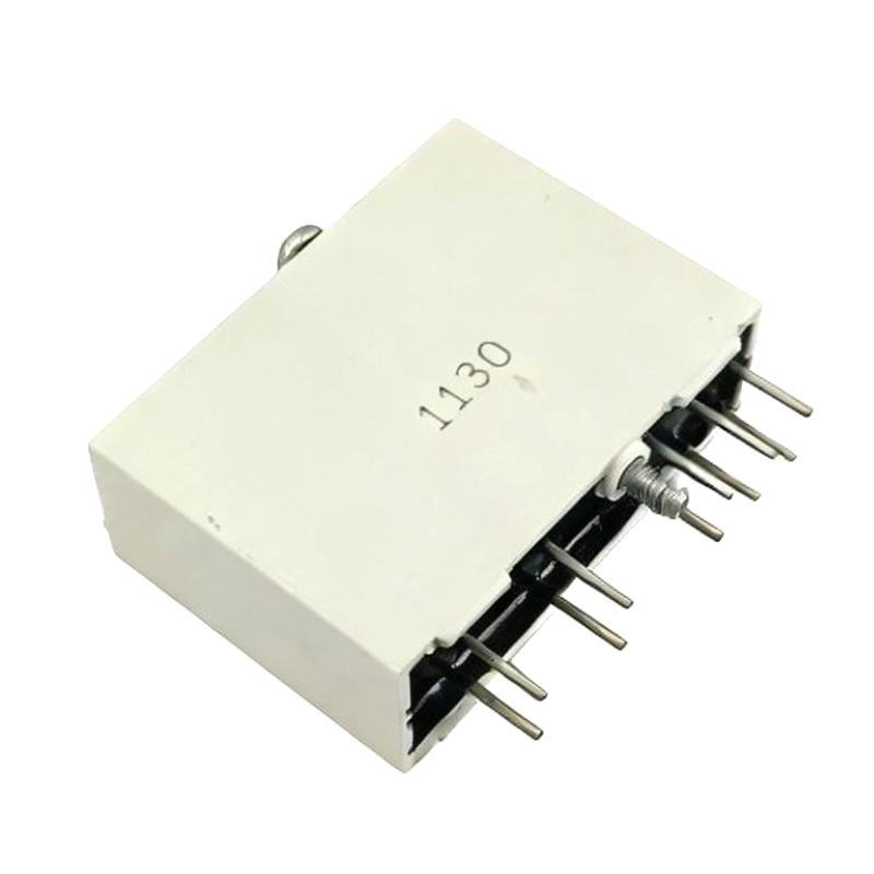
- I/O Relay Module
- USA
- 88 × 30 × 50 mm
- 0.1 kg
- Xiamen, China
- New & In Stock
- T/T, PayPal, Western Union
- 1 Year
- 1-3 Working Days
- DHL, UPS, TNT, FedEx and EMS.
- 24-Hour Service
- COO
- 68
Our advantage

Global Logistics
We have a 10-year logistics and express cooperation agreement, so our products can be shipped to any place in the world.

Brand new and original
Our products are imported in bulk from the place of origin. Because of the cooperative relationship, our products are all original and 100% new.

24-hour service
We provide 7*24 hours service to our customers. We will be there whenever you need us.

Price advantage
All our products are priced very favorably because we have our own warehouse and supply.
| Company Information | |||
| [email protected] | |||
| Mobile | +8615980777398 | ||
| +8615980777398 | |||
| 15980777398 |
Product Overview
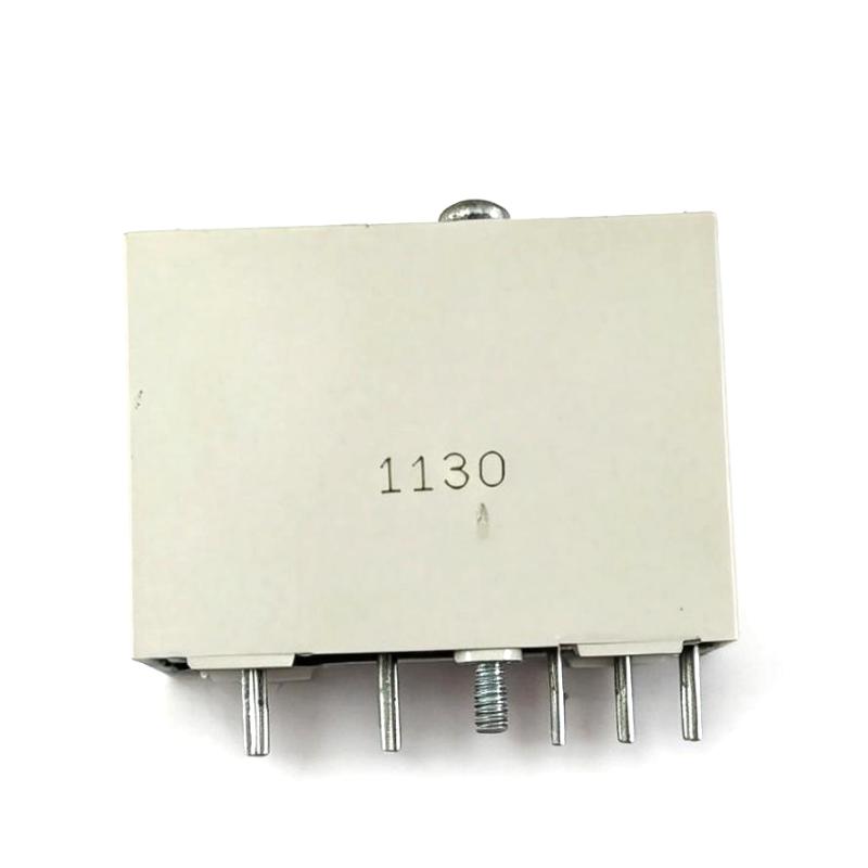
The Honeywell 51190523-125 I/O Relay Module is an interface component used to connect control-system signals with external electrical circuits. Its relay-based architecture allows a control signal to operate or isolate another circuit while maintaining electrical separation between the control side and the switched side.
In an industrial control cabinet, an I/O relay module is commonly positioned between system I/O hardware and field equipment. This arrangement can be useful when the signal from a controller is not directly suitable for the voltage, current, or switching characteristics of the connected load.
The 51190523-125 can therefore serve as an intermediate switching and isolation point in a Honeywell control architecture. Depending on the system configuration, the relay interface may be associated with discrete control signals, external devices, alarms, contactors, solenoids, or other field circuits.
For replacement work, the relay’s electrical characteristics and the host I/O architecture should be checked together. A relay module that fits mechanically may still be unsuitable if its coil, contact arrangement, switching rating, or system interface does not match the original installation.
Technical Specifications
| Parameter | Specification |
|---|---|
| Manufacturer | Honeywell |
| Model | 51190523-125 |
| Product Type | I/O Relay Module |
| Primary Function | Signal Switching and Electrical Isolation |
| Application | Industrial Control and I/O Interface |
| System Role | Relay Interface Between Control and Field Circuits |
| Installation | Control Cabinet / I/O System |
| Dimensions | 88 × 30 × 50 mm |
| Weight | 0.1 kg |
The supplied product data identifies the unit as an I/O Relay Module. Specific coil voltage, contact configuration, contact rating, and terminal assignment should be verified against the system documentation before electrical replacement.
Product Features
The 51190523-125 combines relay switching with I/O interfacing, making it useful where the control-system signal needs to operate an external electrical circuit through a relay contact.
Key characteristics include:
- Honeywell I/O Relay Module
- Relay-based signal switching
- Provides electrical separation between control and field circuits
- Suitable for industrial control cabinet applications
- Interfaces control-system signals with external loads
- Useful for discrete control applications
- Can support switching of external devices where compatible
- Compact module construction
- Suitable for system maintenance and replacement
- Dimensions of 88 × 30 × 50 mm
- Stated weight of 0.1 kg
The relay should be selected according to the actual electrical load. Inductive loads such as contactor coils and solenoids can impose different switching requirements from simple resistive loads.
Working Principle
The 51190523-125 uses a relay interface to transfer a control command from the I/O side to an external circuit.
A simplified signal path is:
Controller / I/O Output → Relay Coil → Relay Contacts → External Load
When the control side energizes the relay coil, the relay changes the state of its contacts. The switched contacts can then control or isolate a separate electrical circuit according to the relay configuration.
This arrangement creates a useful separation between the low-level control interface and the external circuit. The controller does not necessarily have to carry the load current directly; instead, the relay contacts perform the switching function.
For example, a PLC or Honeywell control output may command a relay, while the relay contact is used to operate a compatible contactor, solenoid, alarm circuit, or other external device.
The relay therefore acts as an electrical interface and switching element, rather than as an independent controller.
Role in a Honeywell I/O System
The 51190523-125 occupies the interface layer between Honeywell control electronics and external field circuits.
A typical arrangement can be represented as:
Controller → I/O Output → 51190523-125 → Field Device
The relay module can be useful when direct connection between the controller output and field load is undesirable or electrically unsuitable.
For example, the relay can provide a switching interface between a control-system output and a field circuit with different electrical characteristics. It can also make troubleshooting more structured because the control side and switched side can be checked independently.
In a larger control cabinet, relay modules may also be used to organize discrete outputs and provide a consistent interface between system electronics and external equipment.
The actual role of the 51190523-125 depends on how it is wired within the specific Honeywell installation.
Industrial Applications
The 51190523-125 is suitable for industrial applications requiring relay-based switching between control-system I/O and external electrical circuits.
| Application | Typical Use |
|---|---|
| Industrial Control Cabinets | Interfacing controller outputs with field circuits |
| Process Control | Switching external control devices |
| Motor Control | Interfacing with contactors or auxiliary circuits |
| Solenoid Control | Switching compatible solenoid circuits |
| Alarm Systems | Relay-based alarm or annunciation interfaces |
| Utility Equipment | Isolating control signals from external circuits |
| Machinery Control | Switching discrete field devices |
| Safety-Related Equipment | Signal isolation where supported by the system design |
| Building / Plant Equipment | Interfacing control outputs with external loads |
The suitability of the relay for a specific load depends on the actual coil and contact electrical ratings, switching frequency, load type, and required protection.
Installation and Maintenance
The 51190523-125 should be installed according to the electrical arrangement of the host Honeywell system and the connected field circuit.
Before replacement, identify both sides of the relay interface. This is important because a relay fault can produce symptoms on either the controller side or the field-device side.
Recommended checks include:
- Confirm the complete 51190523-125 part number.
- Verify the host I/O system compatibility.
- Identify the relay coil circuit.
- Identify the switched contact circuit.
- Confirm the required coil voltage.
- Check the field load characteristics.
- Verify contact wiring and terminal assignments.
- Isolate power before servicing.
- Inspect terminals for looseness or overheating.
- Check for damaged wiring or insulation.
- Inspect relay contacts for signs of excessive wear.
- Verify the connected load is within the relay’s rating.
- Test relay operation after installation.
- Confirm the controller recognizes the expected output state.
- Verify the external device responds correctly.
When the relay is used with inductive loads, the associated suppression or protection arrangement should also be checked. Repeated contact damage can indicate excessive switching stress rather than a simple relay-module failure.
Related Components
The 51190523-125 normally works together with several components in the control and field interface chain.
| Component | Function |
|---|---|
| Honeywell Controller | Generates control logic and commands |
| Digital Output Module | Provides the control-side output signal |
| Relay Module | Switches and isolates the external circuit |
| Terminal Blocks | Connect control and field wiring |
| Contactor | Switches higher-power electrical loads |
| Solenoid Valve | Converts electrical command into mechanical action |
| Alarm Device | Provides local or remote notification |
| Field Wiring | Carries signals and power between cabinet and equipment |
| Circuit Protection | Protects associated electrical circuits |
| Control Cabinet | Houses the I/O and interface hardware |
The relay module should be treated as part of the complete signal path rather than as an independent switching device.
Recommended Related Models
When selecting replacement or associated components, the most important factors are the required I/O function, relay interface, coil characteristics, contact configuration, and field-load requirements.
| Model / Component | Product Type | Typical Application |
|---|---|---|
| Honeywell 51190523-125 | I/O Relay Module | Control-to-field relay interface |
| Honeywell Digital Output Modules | I/O Module | Discrete control signal generation |
| Honeywell I/O Interface Modules | Interface Hardware | Field signal integration |
| Honeywell Control Modules | Control Hardware | Processing and control logic |
| Honeywell Terminal Assemblies | Wiring Interface | Field and cabinet connections |
| Honeywell Power Supply Modules | Power Supply | Supplying compatible control hardware |
For direct replacement, the 51190523-125 part number should be matched first. If an alternative relay module is being considered, the coil voltage, contact arrangement, switching capacity, load type, and installation method must all be checked.
Key Advantages
- Honeywell I/O Relay Module.
- Provides relay-based signal switching.
- Separates control-side and field-side circuits.
- Suitable for discrete industrial control applications.
- Useful for interfacing controller outputs with external devices.
- Supports organized control-cabinet wiring.
- Can simplify isolation and troubleshooting between control and field circuits.
- Suitable for applications involving contactors, solenoids, alarms, and other compatible loads.
- Compact 88 × 30 × 50 mm dimensions.
- Stated weight of 0.1 kg.
Technical FAQs
Why would a Honeywell I/O system use a relay interface instead of driving a field device directly?
A relay can provide electrical separation and a different switching interface between the controller output and the external circuit. This is useful when the field load has electrical characteristics that should not be connected directly to the controller’s I/O output.
What is the first electrical parameter to verify when replacing the 51190523-125?
The relay coil requirements should be matched to the control-side output, while the contact arrangement and switching rating must be checked against the field circuit. Both sides need to be compatible; matching only the coil voltage is not sufficient.
Why can an inductive load cause problems for an otherwise correctly selected relay module?
Contactors, solenoids, and similar devices can generate transient voltage when their coils are switched. These transients can increase contact wear and electrical stress. The load type and any required suppression arrangement should therefore be considered when troubleshooting repeated relay failures.
How can a technician distinguish a relay-module fault from a controller-output fault?
Check the signal path in stages. First verify that the controller is issuing the expected output command, then check the relay coil side, followed by the relay contact state and finally the field device. This separates the control-side problem from the switching and load-side portions of the circuit.