

ProductPRODUCT
Featured products
Contact Us
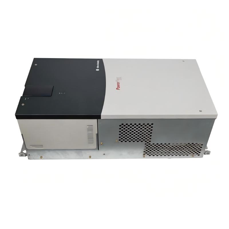
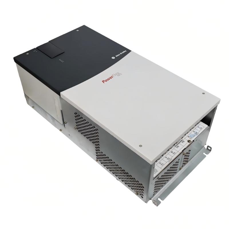
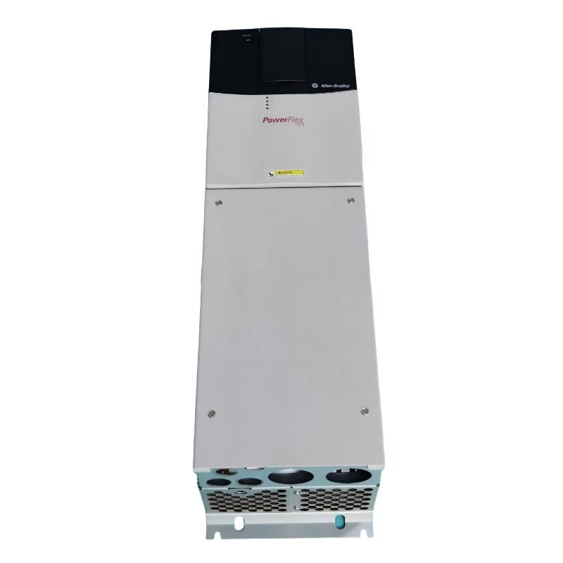
- Allen Bradley
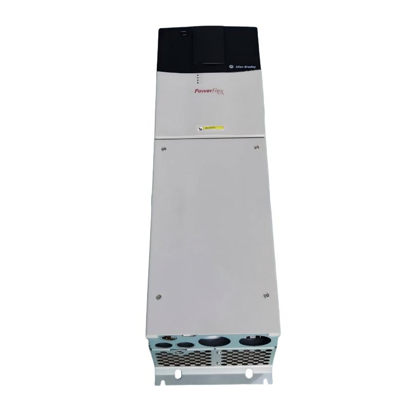
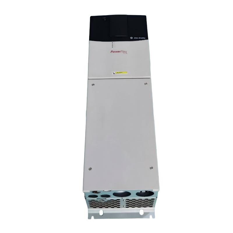
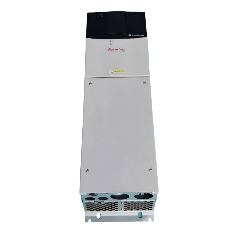
- 20BC085A0ANNANC0
- PowerFlex AC Drive
- USA
- 220.0 × 758.8 × 201.7 mm
- 24.49kg
- Xiamen, China
- New & In Stock
- T/T, PayPal, Western Union
- 1 Year
- 1-3 Working Days
- DHL, UPS, TNT, FedEx and EMS.
- 24-Hour Service
- COO
- 3
Our advantage

Global Logistics
We have a 10-year logistics and express cooperation agreement, so our products can be shipped to any place in the world.

Brand new and original
Our products are imported in bulk from the place of origin. Because of the cooperative relationship, our products are all original and 100% new.

24-hour service
We provide 7*24 hours service to our customers. We will be there whenever you need us.

Price advantage
All our products are priced very favorably because we have our own warehouse and supply.
| Company Information | |||
| [email protected] | |||
| Mobile | +8615980777398 | ||
| +8615980777398 | |||
| 15980777398 |
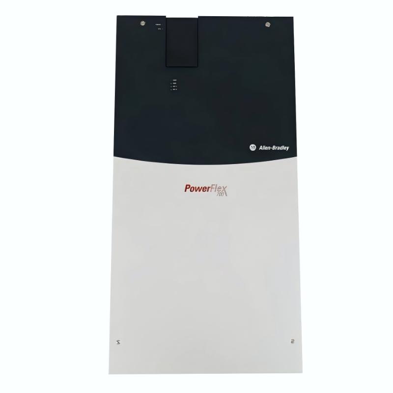
Allen-Bradley 20BC085A0ANNANC0 AC Drive: Technical Specifications, Product Overview, Applications, Advantages, and Related Models
1. Product Overview
The 20BC085A0ANNANC0 is an industrial adjustable-frequency AC drive from the PowerFlex 700 series. It is designed to control the speed and operation of compatible three-phase AC motors in industrial machinery, material-handling systems, and process equipment.
The model belongs to the 400 V-class, 85 A drive range. Its associated power ratings are approximately 45 kW for normal-duty applications and 37 kW for heavy-duty applications. These ratings describe different operating duty categories and should not be treated as interchangeable without checking the load requirements.
This configuration is associated with standard drive control and 24 V I/O, with no communication module specified. It is also listed without a drive-mounted braking resistor. The complete suffix matters when determining the exact braking hardware, feedback options, control interface, and other configuration details.
The PowerFlex 700 platform is intended for industrial applications that need adjustable motor speed, controlled acceleration and deceleration, and integration with machine-control systems. Typical uses include conveyors, pumps, fans, mixers, and general-purpose production machinery.
The specifications below distinguish between the model’s general electrical ratings and details that should be verified against the unit’s nameplate or installation drawing. This is especially important for dimensions, weight, and option-dependent features.
2. Brand and Product Series
|
Item |
Description |
|---|---|
|
Brand |
Allen-Bradley |
|
Model number |
|
|
Product category |
Adjustable-frequency AC drive / variable-frequency drive |
|
Product series |
PowerFlex 700 |
|
Drive type |
Industrial AC motor drive |
|
Supply voltage class |
400 V-class, three-phase |
|
Rated output current |
85 A |
|
Normal-duty power rating |
Approximately 45 kW |
|
Heavy-duty power rating |
Approximately 37 kW |
|
Enclosure class |
IP20 / NEMA Type 1 family configuration; verify exact catalog suffix |
|
Control arrangement |
Standard control; confirm the exact I/O configuration |
|
Communication option |
No communication module specified for this configuration |
|
Braking resistor |
No drive-mounted braking resistor specified |
|
Application type |
Industrial motor speed and torque control |
|
Installation type |
Electrical control-panel installation |
|
Product generation |
Established industrial drive platform |
3. Technical Parameters
3.1 Electrical Specifications
|
Parameter |
Specification |
|---|---|
|
Model |
20BC085A0ANNANC0 |
|
Product series |
PowerFlex 700 |
|
Nominal input voltage |
400 V AC class |
|
Typical voltage class |
380–480 V AC; verify the exact nameplate range |
|
Input phase |
Three-phase |
|
Output phase |
Three-phase |
|
Rated output current |
85 A |
|
Normal-duty rating |
Approximately 45 kW |
|
Heavy-duty rating |
Approximately 37 kW |
|
Supply frequency |
Typically 50/60 Hz, depending on the specific drive configuration |
|
Output frequency range |
Configuration-dependent; verify the applicable manual |
|
Overload capability |
Depends on duty category, overload duration, ambient conditions, and drive settings |
|
Motor compatibility |
Three-phase AC motor, subject to rated voltage, current, and load requirements |
|
Control type |
Standard drive control |
|
Control I/O |
Confirm the installed control-board configuration |
|
Communication interface |
No communication module specified |
|
Feedback option |
Confirm from the complete catalog number and installed hardware |
|
Dynamic braking |
Confirm whether a braking transistor is installed; do not assume it is included |
|
Braking resistor |
No drive-mounted resistor specified |
|
EMC provisions |
Confirm the filter and common-mode choke configuration on the nameplate or parts list |
|
Protective functions |
Available functions depend on the exact hardware and configured parameters |
|
Motor overload protection |
Must be configured and applied according to the motor and drive requirements |
|
Application rating |
Select normal-duty or heavy-duty capacity according to the actual load |
The 85 A rating is a key selection parameter, but it should not be used in isolation. The motor’s full-load current, starting torque, load inertia, operating speed, ambient temperature, and overload requirements all affect the final selection.
The normal-duty rating of approximately 45 kW and heavy-duty rating of approximately 37 kW refer to different application conditions. A machine with frequent starts, high starting torque, or sustained overloads may require the heavy-duty rating even if its nominal power appears to fit within the normal-duty range.
3.2 Mechanical and Installation Parameters
|
Parameter |
Specification |
|---|---|
|
Model |
20BC085A0ANNANC0 |
|
Product family |
PowerFlex 700 |
|
Frame size |
Expected Frame 4 for this 85 A configuration; confirm the nameplate |
|
Enclosure protection |
Commonly IP20 / NEMA Type 1 for this configuration class; verify exact suffix |
|
Approximate width |
220.0 mm |
|
Approximate height |
758.8 mm |
|
Approximate depth |
201.7 mm |
|
Approximate dimensions in centimetres |
22.0 × 75.88 × 20.17 cm |
|
Approximate net weight |
24.5 kg |
|
Approximate packaged weight |
Not confirmed for this exact catalog number |
|
Mounting arrangement |
Panel-mounted; confirm the specific mounting drawing |
|
Ventilation |
Required; follow the manufacturer’s clearance and airflow instructions |
|
Installation environment |
Protected industrial control-panel environment |
|
Maximum altitude without derating |
Commonly 1,000 m for this product class; verify the applicable manual |
|
Humidity |
Avoid condensation; confirm the model-specific environmental limits |
|
Service access |
Allow clearance for wiring, inspection, cooling, and maintenance |
|
Cabinet design |
Must account for drive heat loss, cable bending radius, and required clearances |
Dimensions and weight note: The dimensions and net weight above are approximate reference figures for the 85 A PowerFlex 700 frame configuration, not a verified dimensional drawing for every suffix. Mounting brackets, accessories, and hardware revisions can affect the final installation envelope. Confirm the precise dimensions and weight of the supplied unit before designing a cabinet or planning a replacement.
4. Product Introduction and Operating Principle
4.1 Adjustable-Frequency Motor Control
The 20BC085A0ANNANC0 is designed to vary the frequency and voltage supplied to a compatible AC motor. By changing the output frequency, the drive can adjust the motor’s operating speed instead of requiring the motor to run continuously at a fixed speed.
This is useful in production environments where equipment must operate at different speeds during startup, normal production, material transfer, or shutdown. A conveyor, for example, may need a slower speed during loading and a higher speed once the production line is running normally.
4.2 Vector Control
This model is configured for vector control. Vector-control methods are intended to provide more effective control of motor torque and speed than basic open-loop voltage-frequency control in suitable applications.
The actual performance depends on motor data, parameter settings, motor identification procedures, and the operating conditions. Correct commissioning is especially important when the application requires consistent torque at low speeds or responds to rapidly changing loads.
4.3 Industrial Input and Output Control
The specified configuration uses 24 V I/O and does not include a dedicated communication module. This arrangement can suit systems where the drive receives commands and speed references through compatible hardwired signals.
Before installation, confirm the terminal assignments, available input and output functions, and the control scheme. If the machine depends on a fieldbus network, a communication option or a different drive configuration may be needed.
4.4 Electrical Interference Management
The listed configuration includes an EMC filter and common-mode choke. These components can help manage certain forms of electrical interference associated with drive operation.
Good installation practices remain essential. Grounding, motor-cable routing, shielding, separation of control and power wiring, and compliance with the applicable electrical requirements all contribute to reliable operation.
4.5 Industrial Panel Installation
The drive uses an IP20 / NEMA Type 1 enclosure configuration. It is intended for a suitable electrical installation rather than direct exposure to water, rain, or heavy contamination.
The control cabinet should provide sufficient ventilation, electrical clearance, protection from contamination, and access for maintenance. The panel design must also account for the heat produced by the drive during normal operation.
5. Product Applications

5.1 Conveyor and Material-Handling Systems
Conveyor systems frequently require adjustable speed, smooth startup, and predictable stopping. The drive can help operators match belt speed to production demand and reduce abrupt mechanical movement.
Typical applications include assembly lines, packaging lines, warehouse material handling, and production transfer systems. The motor current, belt inertia, loaded-start requirements, and stopping time should be checked during selection.

5.2 Industrial Pumping Systems
Pumps used in water circulation, process-fluid transfer, and industrial utility systems may need to operate at different flow rates. Variable-speed control can help match pump output to demand when the pump and process are suitable for this operating method.
Pump curves, minimum flow, pressure limits, motor cooling, and the potential for water hammer should be considered before setting speed ramps or operating limits.

5.3 Fans and Ventilation Equipment
Industrial fans and ventilation systems may need to deliver different airflow levels depending on temperature, production demand, or working conditions. A drive can provide adjustable speed and reduce unnecessary full-speed operation where the fan and process allow it.
Continuous low-speed operation should be assessed carefully to ensure adequate motor cooling and operation within the manufacturer’s permitted speed range.

5.4 Mixers and Agitators
Mixing equipment can experience changing torque as the material becomes thicker, heavier, or more difficult to move. Adjustable speed can help tailor the process to different materials and production stages.
The required starting torque, maximum load, operating speed range, and frequency of starts should be assessed before deciding whether the drive’s normal-duty or heavy-duty rating is appropriate.

5.5 General Production Machinery
Industrial rollers, feeders, processing machines, and other motor-driven systems may benefit from adjustable operating speed and controlled acceleration.
The drive can be integrated into a suitable control system, provided that its I/O arrangement, speed-reference method, feedback requirements, and communication options match the machine design.
These are typical application categories rather than a guarantee of suitability for every machine. The correct selection depends on the motor nameplate, load characteristics, duty cycle, control architecture, and installation conditions.
6. Product Advantages
6.1 Suitable for Higher-Power Industrial Loads
The 85 A output-current rating places this model in a higher-power industrial drive class. Its approximately 45 kW normal-duty rating makes it relevant to machinery that needs more capacity than small compact drives can provide.
The actual application rating must still be checked. Motor current, overload demand, ambient temperature, and installation conditions may limit the usable capacity.
6.2 Flexible Motor-Speed Adjustment
The drive allows motor speed to be adjusted to match the production process. This can improve operational flexibility when the same machine needs to handle different materials, production rates, or operating stages.
In suitable pump and fan applications, variable-speed control may also reduce energy consumption when the system spends substantial time operating below full speed.
6.3 Controlled Starting and Stopping
Acceleration and deceleration settings can be adjusted to reduce sudden changes in speed. When correctly configured, this may help limit mechanical shock on belts, couplings, gearboxes, shafts, and driven equipment.
The appropriate ramp time depends on load inertia and the required stopping performance. Rapid deceleration may require braking hardware or another energy-management method, which is not included in the specified configuration.
6.4 Vector-Control Capability
Vector control can provide useful motor-speed and torque regulation when the motor data and drive parameters are configured correctly. This can benefit applications where load conditions vary or more responsive motor control is required.
Performance is application-dependent, and the drive should be commissioned using the correct motor parameters and operating procedure.
6.5 Hardwired Control Flexibility
The 24 V I/O arrangement supports compatible hardwired control systems. It can be suitable for installations where a PLC, relay logic, or machine controller provides the necessary control signals.
Because the model does not have a communication module installed in the listed configuration, any requirement for network communication must be evaluated separately.
6.6 EMC Filter and Common-Mode Choke
The included EMC filter and common-mode choke provide electrical-interference management features that can be useful in industrial control panels.
Their effectiveness depends on correct installation, grounding, wiring practices, and the overall system design. They do not eliminate the need to follow the installation instructions.
6.7 Established Industrial Drive Platform
The PowerFlex 700 family has been used in industrial motor-control applications for many years. This can be helpful when maintaining existing equipment, documenting an installed system, or assessing whether a like-for-like replacement is feasible.
However, the family is discontinued, so availability, repair options, and long-term support should be considered as part of any purchasing decision.
7. Limitations and Important Selection Notes
7.1 No Brake IGBT and No Drive-Mounted Braking Resistor
The specified catalog configuration is listed without a braking IGBT and without a drive-mounted braking resistor. If the machine has a high-inertia load, needs frequent rapid stops, or must control an overhauling load, the braking requirements need a separate engineering review.
Do not assume that an external resistor can be connected without checking the drive hardware, approved braking arrangement, resistor sizing, wiring, and thermal limits.
7.2 No Communication Module Installed
The listed model does not include a communication module. This is important if the existing machine uses an industrial network to exchange commands, speed references, status information, or fault data.
A replacement drive with the same current rating may still be unsuitable if its network interface or control architecture differs from the original system.
7.3 No Feedback Option Specified
The configuration is listed without a feedback option. If the application relies on encoder feedback or closed-loop speed control, the installed hardware and required control method must be verified before selection.
7.4 IP20 / NEMA Type 1 Enclosure
The drive is intended for an appropriate protected installation. It should not be treated as a waterproof or unrestricted outdoor device.
Dust, moisture, corrosive substances, condensation, and cabinet temperature can affect reliability. An appropriate enclosure and ventilation strategy should be selected for the installation environment.
7.5 Discontinued Product Status
The PowerFlex 700 product family has reached discontinued status. A replacement decision may therefore involve a remaining-stock unit, a refurbished drive, repair of an existing unit, or an engineered replacement from a newer drive family.
The most suitable option depends on the importance of downtime, the condition of the existing equipment, the control system, and the availability of technical support.
8. Five Related Models in the Same Series
The following models are useful starting points for comparing PowerFlex 700 configurations and nearby power ratings. Exact catalog suffixes matter: models with similar current ratings can differ in braking hardware, control voltage, communication options, feedback, and filtering.
|
Model |
Series |
Voltage class |
Current / power rating |
Configuration or application notes |
Approx. dimensions (W × H × D) |
Approx. net weight |
|---|---|---|---|---|---|---|
|
20BC085A0ANNANC0 |
PowerFlex 700 |
400 V AC, 3-phase |
85 A; 45 kW normal duty / 37 kW heavy duty |
Target configuration; IP20 / Type 1, vector control, 24 V I/O, no HIM, no brake IGBT, no resistor, no communication module, no feedback |
220.0 × 758.8 × 201.7 mm |
24.49 kg |
|
20BC085A0ANNANA0 |
PowerFlex 700 |
400 V AC, 3-phase |
85 A; 45 kW normal duty / 37 kW heavy duty |
Closely related 85 A configuration; verify the complete option suffix and installed hardware |
Approx. 220.0 × 758.8 × 201.7 mm |
Approx. 24.5 kg |
|
20BC085A0ANNADA0 |
PowerFlex 700 |
400 V AC, 3-phase |
85 A; 45 kW normal duty / 37 kW heavy duty |
Related configuration listed with a DeviceNet communication option; confirm exact catalog availability and interface requirements |
Approx. Frame 4 dimensions; verify drawing |
Approx. 24.5 kg |
|
20BC105A0ANNANC0 |
PowerFlex 700 |
400 V AC class |
Higher-current class; verify exact duty rating |
Higher-current family option for applications requiring more current capacity; requires a full load and installation review |
Larger frame may apply; confirm drawing |
Confirm exact configuration |
|
20BC140A0ANNANC0 |
PowerFlex 700 |
400 V AC class |
Higher-current class; verify exact duty rating |
Higher-capacity family option; check input protection, motor current, cabinet space, and cooling requirements |
Confirm exact frame drawing |
Confirm exact configuration |
Dimensions and weight: The 24.49 kg net weight and 220.0 × 758.8 × 201.7 mm frame dimensions are the published reference values for the target 85 A Frame 4 configuration. For the other models, figures are shown as approximate or unconfirmed where exact model-specific mechanical data has not been established. Obtain the correct mechanical drawing before making mounting or shipping arrangements.
8.1 Model Selection Guidance
– 20BC085A0ANNANC0: Use as the baseline when the application needs the same 85 A PowerFlex 700 configuration.
– 20BC085A0ANNANA0: Consider as a nearby catalog configuration, but compare the entire suffix and hardware details before treating it as equivalent.
– 20BC085A0ANNADA0: Consider only if its communication arrangement matches the control system. A network option can change how the drive is integrated into the machine.
– 20BC105A0ANNANC0: Consider if a higher current rating may be needed. Check the motor current and the applicable normal-duty and heavy-duty ratings.
– 20BC140A0ANNANC0: Consider for higher-current applications only after confirming the exact model, physical size, electrical ratings, and required protective devices.
These are comparison candidates, not automatic drop-in replacements. Even when the power rating is similar, a different option set can require wiring changes, control-system changes, new parameter settings, or a different cabinet arrangement.
9. Five Other Popular Models from the Same Brand
The following models represent other drive options from the same brand across compact and larger industrial product families. The smaller PowerFlex 525 models are intended for much lower power levels than the 20BC085A0ANNANC0. The larger industrial families may be relevant to engineered modernization projects, but a full technical comparison is necessary.
|
Model |
Series |
Voltage class |
Approximate rating / range |
Main characteristics |
Approx. dimensions (W × H × D) |
Approx. net weight |
|---|---|---|---|---|---|---|
|
25B-D2P3N104 |
PowerFlex 525 |
480 V-class configuration |
Approximately 2.3 A output; small motor range |
Compact adjustable-speed drive for small machinery; exact power rating depends on the applicable rating table |
Verify exact frame drawing |
Verify exact model weight |
|
25B-D6P0N104 |
PowerFlex 525 |
480 V-class configuration |
Approximately 6.0 A output; small-to-medium motor range |
Compact drive for conveyors, fans, pumps, and general machinery |
Verify exact frame drawing |
Verify exact model weight |
|
25B-D010N104 |
PowerFlex 525 |
480 V-class configuration |
Approximately 10 A output; small-to-medium motor range |
General-purpose variable-speed control in compact installations |
Verify exact frame drawing |
Verify exact model weight |
|
20F11ND077AA0NNNNN |
PowerFlex 753 |
Catalog-dependent; verify nameplate |
Higher-power industrial drive; confirm exact current and power |
Modular industrial drive family with configurable control and integration options |
Confirm frame and accessories |
Confirm exact configuration |
|
20G11NC060JA0NNNNN |
PowerFlex 755 |
Catalog-dependent; verify nameplate |
Industrial drive range; confirm exact current and power |
Industrial motor-control family with broader control and integration possibilities |
Confirm frame and accessories |
Confirm exact configuration |
The listed PowerFlex 525 examples have substantially lower current ratings than the target 85 A drive. They should not be selected as replacements for the target model merely because they belong to the same brand.
The PowerFlex 753 and 755 examples are included as potential modernization candidates, not verified equivalent replacements. Their complete catalog numbers, voltage classes, current ratings, options, and mechanical requirements must be confirmed before use.
10. Comparison of Related Product Families
|
Feature |
PowerFlex 700 |
PowerFlex 525 |
PowerFlex 753 |
PowerFlex 755 |
|---|---|---|---|---|
|
General purpose |
Established industrial motor drive |
Compact general-purpose drive |
Configurable industrial drive |
Advanced industrial drive family |
|
Typical application scale |
Medium-to-high power motor control |
Small-to-medium machinery |
Medium-to-high power applications, depending on configuration |
Industrial applications with broader control requirements |
|
Installation space |
Frame-specific; target model uses Frame 4 |
Generally compact; depends on current rating |
Depends on drive frame and options |
Depends on drive frame and options |
|
Control flexibility |
Depends on installed hardware and options |
Depends on model and configuration |
Depends on selected configuration |
Depends on selected configuration |
|
Communication |
Option-dependent |
Model-dependent |
Option-dependent |
Option-dependent |
|
Braking |
Depends on exact hardware |
Depends on exact model and braking requirements |
Depends on exact hardware |
Depends on exact hardware |
|
Replacement suitability |
Baseline product family for the target model |
Not a direct substitute for the 85 A model |
Possible engineering replacement candidate |
Possible engineering replacement candidate |
11. Installation and Maintenance Recommendations
11.1 Verify the Motor Nameplate
Before selecting or replacing the drive, record the motor’s rated voltage, full-load current, frequency, power, speed, and connection type. The drive’s current capacity must be suitable for the motor and the actual operating load.
11.2 Confirm the Duty Category
Determine whether the load requires normal-duty or heavy-duty operation. Applications with frequent acceleration, high starting torque, or repeated overloads may need a different selection from a continuously operating, relatively steady load.
11.3 Confirm the Control Wiring
Review the required start, stop, enable, speed-reference, and status signals. Confirm the I/O voltage and terminal configuration rather than relying solely on the product family’s general capabilities.
11.4 Review Network Requirements
If the existing drive communicates with a PLC or HMI over an industrial network, record the protocol, hardware module, node address, and required data exchange. The target configuration has no communication module specified, so the network arrangement needs special attention.
11.5 Assess Braking and Stopping Time
Determine whether the machine can stop using a controlled deceleration ramp or needs dedicated braking hardware. High-inertia loads, rapid stops, and overhauling loads may require a different configuration or an engineered braking system.
11.6 Check Cabinet Space and Cooling
Use the correct dimensional drawing to confirm the width, height, depth, mounting holes, cable-entry space, and maintenance clearances. The cabinet must also dissipate the heat generated by the drive and maintain the required operating environment.
11.7 Review Electrical Protection
Protective devices, conductor sizing, grounding, and isolation should follow the applicable drive documentation and local electrical codes. Do not choose fuses or circuit breakers solely from the drive’s nominal output current.
11.8 Plan for the Product Lifecycle
Since the PowerFlex 700 family is discontinued, assess whether repair, an existing-stock replacement, or a newer drive platform offers the best long-term outcome. Include the cost of commissioning, control-system changes, and downtime in the comparison.
12. Overall Product Assessment
The 20BC085A0ANNANC0 is a PowerFlex 700 industrial AC drive rated at 85 A, with approximately 45 kW normal-duty and 37 kW heavy-duty capability. Its configuration is associated with 400 V-class three-phase operation, vector control, 24 V I/O, an IP20 / NEMA Type 1 enclosure, conformal coating, an EMC filter, and a common-mode choke.
Its principal strengths are adjustable motor-speed control, controlled acceleration and deceleration, and suitability for a range of industrial motor-driven processes. It can be relevant to conveyors, pumps, fans, mixers, and other production machinery when the motor and load fall within its ratings.
The main points to check are the absence of a braking IGBT and drive-mounted braking resistor, the lack of an installed communication module, the lack of a specified feedback option, and the need to verify physical dimensions and weight against the actual unit.
For related models, begin with other 85 A PowerFlex 700 configurations if maintaining the existing installation is the priority. If evaluating a newer drive family, compare the electrical ratings, control interfaces, network requirements, braking provisions, mounting dimensions, and commissioning needs before selecting the replacement.