

ProductPRODUCT
Featured products



Contact Us
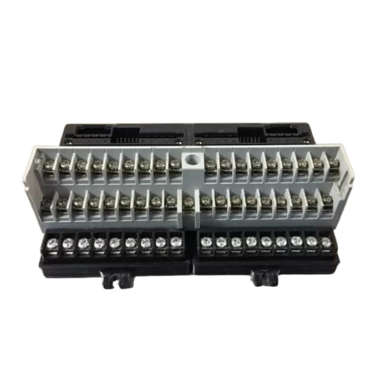
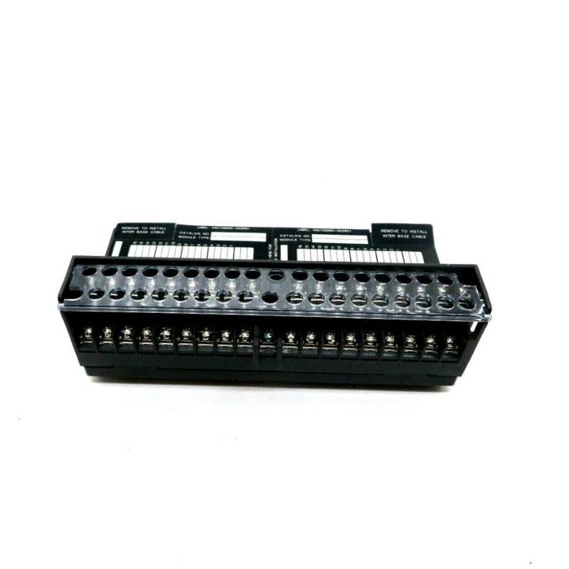
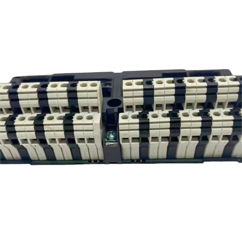
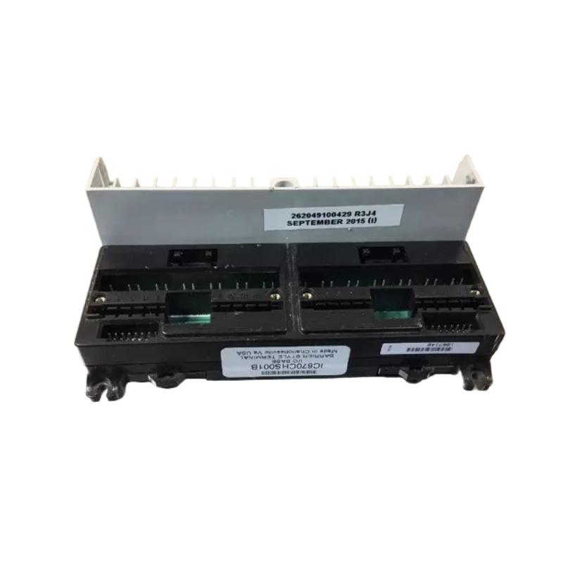
- GE
- IC670CHS001
- I/O Terminal Block
- USA
- 156 × 85 × 50 mm
- 0.22 kg
- Xiamen, China
- New & In Stock
- T/T, PayPal, Western Union
- 1 Year
- 1-3 Working Days
- DHL, UPS, TNT, FedEx and EMS.
- 24-Hour Service
- COO
- 72
Our advantage

Global Logistics
We have a 10-year logistics and express cooperation agreement, so our products can be shipped to any place in the world.

Brand new and original
Our products are imported in bulk from the place of origin. Because of the cooperative relationship, our products are all original and 100% new.

24-hour service
We provide 7*24 hours service to our customers. We will be there whenever you need us.

Price advantage
All our products are priced very favorably because we have our own warehouse and supply.
| Company Information | |||
| [email protected] | |||
| Mobile | +8615980777398 | ||
| +8615980777398 | |||
| 15980777398 |
Product Overview
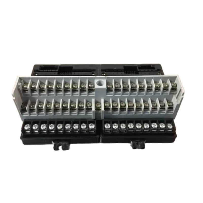
The GE IC670CHS001 I/O Terminal Block is a modular wiring and connection component used within compatible GE industrial automation systems. As an I/O terminal block, its primary role is to provide a structured termination point for field wiring associated with automation inputs and outputs.
In industrial control cabinets, reliable field wiring is essential because sensors, switches, actuators, and other process devices must maintain stable electrical connections with the control system. A properly installed terminal block helps organize field connections, simplify maintenance, and reduce wiring errors.
The supplied product information identifies the GE IC670CHS001 as an I/O Terminal Block, with dimensions of 156 × 85 × 50 mm and a weight of 0.22 kg.
Product Information
- Manufacturer: GE
- Product Family: Industrial Automation / I/O
- Model: IC670CHS001
- Product Type: I/O Terminal Block
- Dimensions: 156 × 85 × 50 mm
- Weight: 0.22 kg
- Application: Industrial Automation
- System Role: I/O Field Wiring and Termination
The IC670CHS001 should be installed as part of a compatible I/O architecture. Before commissioning, verify the terminal block arrangement, associated I/O equipment, field wiring, voltage levels, signal types, and control-system configuration.
Technical Specifications
| Parameter | Specification |
|---|---|
| Manufacturer | GE |
| Model Number | IC670CHS001 |
| Product Type | I/O Terminal Block |
| Dimensions | 156 × 85 × 50 mm |
| Weight | 0.22 kg |
| Application | Industrial Automation |
| System Role | I/O Wiring and Termination |
| Installation | Industrial Control Cabinet |
| Function | Field Signal Connection |
| Maintenance | Wiring / Inspection / Troubleshooting |
The dimensions and weight listed above are based on the product information supplied.
Function and Working Principle
The IC670CHS001 provides a structured termination point between field wiring and the associated automation I/O hardware.
A simplified signal path can be represented as:
Field Device
↓
IC670CHS001 I/O Terminal Block
↓
I/O Module
↓
Controller
↓
Control Logic
For output applications, the signal path operates in the opposite direction:
Controller
↓
I/O Module
↓
IC670CHS001
↓
Field Actuator
The terminal block itself does not replace the controller or I/O processing function. Its primary purpose is to provide the physical electrical connection and organized termination required by the overall control system.
Role in Industrial Control Systems
Terminal blocks play an important role in industrial automation because field devices are often installed throughout a machine or process area while the control equipment is installed inside a cabinet.
A typical architecture is:
Sensors / Switches
↓
Field Wiring
↓
IC670CHS001
↓
I/O Hardware
↓
PLC / Controller
↓
Control Program
↓
Output I/O
↓
IC670CHS001
↓
Actuators
This arrangement separates field wiring from the main control hardware and provides a structured point for inspection and maintenance.
Industrial Applications
Machine Automation
The IC670CHS001 can be used within compatible automation systems to organize field input and output wiring.
Manufacturing Equipment
Production machinery can use organized I/O termination to simplify wiring between sensors, actuators, and control equipment.
Packaging Machinery
Packaging machines often contain numerous discrete field devices. A structured terminal arrangement can make installation and troubleshooting easier.
Material Handling
Conveyors, transfer systems, and automated handling equipment can use I/O terminal connections for field devices.
OEM Machinery
Machine builders can incorporate standardized I/O termination into control cabinets to improve wiring organization.
Industrial Process Equipment
Process equipment can benefit from clearly organized field wiring when numerous signals must be connected to automation hardware.
Installation Guide
1. Confirm the Product Model
Before installation, verify:
GE IC670CHS001
I/O Terminal Block
Do not substitute another terminal block based only on physical appearance.
2. Review the I/O Architecture
Before installing the terminal block, identify:
- Associated I/O equipment
- Input circuits
- Output circuits
- Field devices
- Field power
- Signal voltage
- Signal type
- Terminal assignments
- Control-system configuration
This information should be documented before wiring begins.
3. Verify Electrical Requirements
Before connecting field wiring, verify:
- Supply voltage
- Signal voltage
- Current requirements
- Input type
- Output type
- Common connections
- Polarity where applicable
- Grounding arrangement
Incorrect electrical connections can damage equipment or create unsafe conditions.
4. Back Up Existing Documentation
Before modifying an existing control panel, preserve:
- Wiring diagrams
- Terminal assignments
- I/O lists
- Controller configuration
- Panel documentation
- Field-device information
Photographs can also be useful as a secondary reference during maintenance.
5. Place the Equipment in a Safe State
Before installation:
- Stop automatic operation.
- Place the machine in a safe state.
- Identify affected equipment.
- Isolate electrical energy where required.
- Follow approved lockout/tagout procedures.
- Verify the absence of hazardous energy before working on wiring.
6. Inspect the Terminal Block
Inspect the IC670CHS001 before installation.
Check for:
- Cracked housing
- Damaged terminals
- Bent contacts
- Corrosion
- Contamination
- Mechanical damage
- Loose components
Do not install visibly damaged hardware.
7. Check Cabinet Space
The supplied dimensions are:
156 × 85 × 50 mm
Provide additional clearance for:
- Field wiring
- Cable routing
- Terminal access
- Adjacent hardware
- Maintenance
- Ventilation
The listed dimensions should not be interpreted as the minimum required panel clearance.
8. Install the Terminal Block
Install the IC670CHS001 in the appropriate position within the compatible I/O architecture.
Verify:
- Correct orientation
- Secure mounting
- Proper alignment
- Terminal accessibility
- Clearance from adjacent components
Avoid excessive mechanical force.
9. Connect Field Wiring
Connect field wiring according to the approved system wiring documentation.
For each connection, verify:
- Correct terminal
- Correct wire
- Correct polarity
- Correct voltage
- Correct signal type
- Secure termination
Do not rely solely on wire color when identifying circuits.
10. Label All Connections
Clearly identify field connections.
Recommended information can include:
- Device tag
- I/O address
- Signal description
- Terminal number
- Voltage level
- Cable identification
Clear labeling significantly reduces future maintenance time.
Commissioning Procedure
Step 1 — Visual Inspection
Inspect the IC670CHS001 and all associated wiring.
Step 2 — Verify Terminal Assignments
Compare actual wiring with the approved wiring diagram.
Step 3 — Check Electrical Connections
Verify that connections are tight and correctly terminated.
Step 4 — Verify Field Devices
Confirm that connected sensors, switches, and actuators are correctly wired.
Step 5 — Check Power
Verify the relevant control and field power supplies.
Step 6 — Verify I/O Status
Check the associated I/O module status.
Step 7 — Test Inputs
Activate each applicable field input individually and verify the corresponding control-system indication.
Step 8 — Test Outputs
Command each applicable output under controlled conditions and verify the corresponding field device response.
Step 9 — Check for Abnormal Conditions
Inspect for:
- Unexpected voltage
- Loose connections
- Excessive heating
- Abnormal current
- Incorrect signal response
Step 10 — Return the System to Service
Restore normal operation only after all applicable tests have been completed successfully.
Troubleshooting Guide
Problem 1: Input Signal Is Not Detected
Possible causes include:
- Incorrect wiring
- Loose terminal
- Open field circuit
- Incorrect voltage
- Failed field device
- I/O module problem
- Incorrect terminal assignment
Recommended Checks
- Verify the field device.
- Check the terminal connection.
- Measure the expected signal where appropriate.
- Verify polarity.
- Check the associated I/O channel.
- Compare wiring against the documentation.
Problem 2: Output Device Does Not Operate
Possible causes include:
- Incorrect terminal wiring
- Loose connection
- Missing field power
- Output-channel problem
- Failed actuator
- Incorrect control logic
- Incorrect terminal assignment
Trace the output path from:
Controller → I/O Module → IC670CHS001 → Field Device
This helps determine whether the problem is in the control logic, I/O hardware, terminal block, wiring, or actuator.
Problem 3: Intermittent I/O Signal
Possible causes include:
- Loose terminal
- Damaged conductor
- Vibration
- Corrosion
- Poor connection
- Electrical interference
- Unstable field power
Inspect the complete signal path rather than replacing the terminal block immediately.
Problem 4: Multiple I/O Signals Fail
When several channels fail simultaneously, investigate common components first.
Check:
- Field power supply
- Common wiring
- Terminal connections
- I/O module
- Controller
- Shared wiring paths
A simultaneous failure of several independent field devices may indicate a common upstream problem.
Problem 5: Incorrect Input Status
If an input remains ON or OFF when the field device changes state, check:
- Field-device operation
- Wiring
- Terminal assignment
- Signal voltage
- I/O channel
- Common connection
- Controller configuration
Compare the measured field signal with the status shown by the control system.
Problem 6: Output Remains Energized
Possible causes include:
- Control logic
- Output-channel fault
- Wiring error
- Short circuit
- Incorrect terminal connection
- Field-device problem
First determine whether the output is being commanded by the controller. Then isolate the electrical output path.
Problem 7: Terminal Connection Becomes Hot
Abnormal heating can indicate:
- Loose connection
- Excessive current
- Incorrect conductor size
- High-resistance connection
- Wiring error
- Damaged terminal
Stop operation if a connection becomes abnormally hot and investigate the cause before returning the system to service.
Problem 8: Fault Appears After Rewiring
Check:
- Terminal numbering
- Wire identification
- Signal polarity
- Common connections
- I/O channel assignment
- Controller configuration
Compare the modified wiring against the previous known-good configuration.
Problem 9: Fault Remains After Replacing the Terminal Block
If replacement does not resolve the problem, investigate:
- Field device
- Field wiring
- I/O module
- Power supply
- Controller
- Configuration
- Common wiring
The terminal block may only be one part of the affected circuit.
I/O Diagnostic Strategy
A structured diagnostic sequence is:
Field Device
↓
Field Wiring
↓
IC670CHS001
↓
I/O Module
↓
Controller
For an output circuit:
Controller
↓
I/O Module
↓
IC670CHS001
↓
Field Wiring
↓
Actuator
This approach allows technicians to isolate the failure point logically.
Wiring Inspection Procedure
Input Circuits
For an input circuit:
- Verify the field device.
- Check field power.
- Check wiring continuity where appropriate.
- Verify the terminal.
- Check signal voltage.
- Verify the I/O channel.
- Confirm controller status.
Output Circuits
For an output circuit:
- Verify the controller command.
- Check the I/O channel.
- Verify the terminal connection.
- Check field power.
- Inspect wiring.
- Test the actuator.
Module Replacement Procedure
Phase 1 — Preparation
- Confirm GE IC670CHS001.
- Verify the replacement terminal block.
- Record all terminal assignments.
- Back up wiring documentation.
- Label wires if necessary.
- Place the machine in a safe state.
Phase 2 — Removal
- Stop the equipment.
- Isolate power as required.
- Verify safe conditions.
- Document the existing wiring.
- Disconnect field wiring carefully.
- Remove the existing terminal block.
Phase 3 — Installation
- Inspect the replacement IC670CHS001.
- Confirm the model number.
- Install it correctly.
- Secure the terminal block.
- Reconnect each field circuit.
- Verify each terminal against the wiring documentation.
Phase 4 — Verification
- Check terminal tightness.
- Verify polarity.
- Verify field voltage.
- Confirm I/O channel assignments.
- Inspect the complete wiring assembly.
Phase 5 — Commissioning
- Restore power.
- Check system status.
- Test input channels.
- Test output channels.
- Verify field-device operation.
- Monitor the system during controlled operation.
Preventive Maintenance
| Maintenance Item | Recommended Action |
|---|---|
| IC670CHS001 | Inspect physical condition |
| Terminal Connections | Check condition and security |
| Field Wiring | Inspect for damage |
| Labels | Verify identification |
| Field Power | Check stability |
| I/O Modules | Review status |
| Cabinet | Keep clean and dry |
| Grounding | Verify system arrangement |
| Wiring Documentation | Keep updated |
| Field Devices | Inspect operation |
| Connections | Check for corrosion |
| Diagnostics | Record recurring faults |
Environmental Considerations
Temperature
Maintain the control cabinet within the environmental limits applicable to the complete automation system.
Dust
Prevent excessive dust accumulation around terminal connections and control equipment.
Moisture
Protect the terminal block and wiring from condensation and excessive humidity.
Vibration
Excessive vibration can loosen connections over time.
Electrical Interference
Keep sensitive control wiring appropriately separated from high-current power circuits and major sources of electromagnetic interference.
Common Installation Mistakes
Incorrect Terminal Assignment
Always verify each terminal against the approved wiring documentation.
Loose Connections
Loose field wiring can cause intermittent signals, voltage drops, and localized heating.
Incorrect Polarity
Where the circuit requires polarity, verify the positive and negative connections before energizing the system.
Mixing Signal Types
Do not connect a field circuit to an incorrect I/O channel or terminal.
Poor Wire Identification
Unlabeled wiring increases the risk of maintenance errors.
Insufficient Cabinet Clearance
The IC670CHS001 measures 156 × 85 × 50 mm, but additional space is required for wiring and maintenance access.
Replacing Hardware Without Diagnosing the Circuit
A failed signal does not automatically indicate a terminal-block fault. Always inspect the complete signal path.
Key Advantages
- Provides structured field wiring termination
- Supports organized I/O connections
- Simplifies field-device maintenance
- Facilitates wiring inspection
- Supports modular industrial automation architectures
- Helps separate field wiring from control hardware
- Suitable for machine automation applications
- Suitable for manufacturing equipment
- Suitable for OEM control panels
- Compact dimensions of 156 × 85 × 50 mm
- Low weight of 0.22 kg
Technical FAQs
What is the GE IC670CHS001?
The GE IC670CHS001 is an I/O Terminal Block intended for use within a compatible GE industrial automation I/O architecture.
What is the function of IC670CHS001?
It provides a structured physical termination point for field wiring associated with compatible automation I/O equipment.
What are the dimensions of IC670CHS001?
The supplied dimensions are 156 × 85 × 50 mm.
What is the weight of IC670CHS001?
The supplied weight is 0.22 kg.
Can a terminal-block problem cause an I/O fault?
Yes. Loose, damaged, corroded, or incorrectly connected terminals can interrupt field signals.
Why is an input signal not reaching the controller?
Check the field device, field wiring, IC670CHS001 terminal connection, signal voltage, associated I/O channel, and controller configuration.
Why does an output device not operate?
Check the controller command, I/O channel, terminal connection, field power, wiring, and actuator.
Why are several I/O channels failing simultaneously?
Investigate common power supplies, common connections, the associated I/O module, and controller status before replacing individual components.
Why does an I/O signal work intermittently?
Loose connections, vibration, damaged wiring, corrosion, unstable power, and electrical interference can cause intermittent signals.
Should IC670CHS001 be replaced immediately when an I/O fault occurs?
No. First trace the complete circuit from the field device through wiring and terminal block to the I/O module and controller.
What should be documented before replacing IC670CHS001?
Record terminal assignments, wire identification, I/O channel information, field-device connections, and relevant wiring diagrams.
Can a loose terminal cause overheating?
Yes. A high-resistance connection can generate localized heating, especially when current is significant.
How should an IC670CHS001 fault be diagnosed?
Start at the affected field device and trace the electrical path through field wiring, IC670CHS001, I/O hardware, and controller logic.
Conclusion
The GE IC670CHS001 I/O Terminal Block is a field-wiring and termination component designed for compatible industrial automation systems. The supplied product information specifies dimensions of 156 × 85 × 50 mm and a weight of 0.22 kg.
Reliable operation depends on correct terminal assignment, secure field wiring, appropriate electrical connections, proper I/O configuration, and stable environmental conditions.
During installation, technicians should verify the complete I/O architecture, document terminal assignments, inspect all connections, and confirm signal types and voltage levels before energizing the system.
When troubleshooting an I/O problem, the most effective approach is to trace the complete signal path from the field device through the wiring and IC670CHS001 to the associated I/O module and controller. This systematic method can help identify wiring faults, terminal problems, I/O failures, configuration errors, and field-device issues without unnecessary component replacement.