

ProductPRODUCT
Featured products
Contact Us
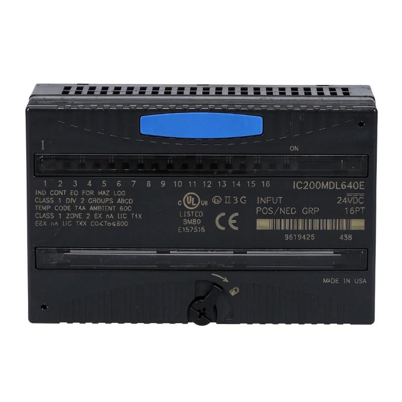
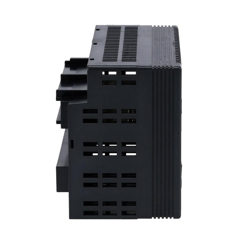
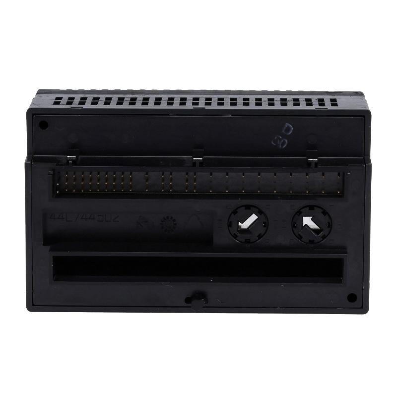
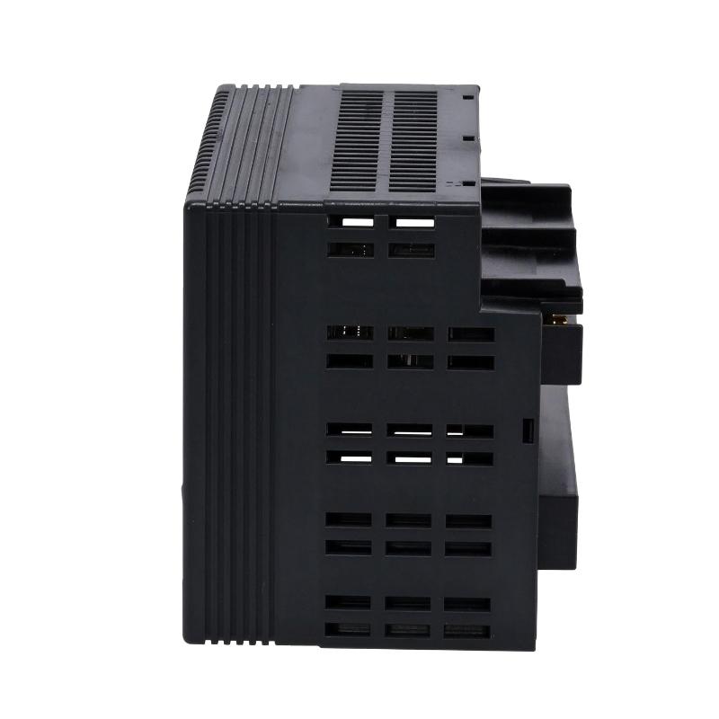
- GE
- IC200MDL640E
- VersaMax Discrete Input Module
- USA
- 110 x 66.8 x 50 mm
- 0.45 kg
- Xiamen, China
- New & In Stock
- T/T, PayPal, Western Union
- 1 Year
- 1-3 Working Days
- DHL, UPS, TNT, FedEx and EMS.
- 24-Hour Service
- COO
- 4
Our advantage

Global Logistics
We have a 10-year logistics and express cooperation agreement, so our products can be shipped to any place in the world.

Brand new and original
Our products are imported in bulk from the place of origin. Because of the cooperative relationship, our products are all original and 100% new.

24-hour service
We provide 7*24 hours service to our customers. We will be there whenever you need us.

Price advantage
All our products are priced very favorably because we have our own warehouse and supply.
| Company Information | |||
| [email protected] | |||
| Mobile | +8615980777398 | ||
| +8615980777398 | |||
| 15980777398 |
Product Overview
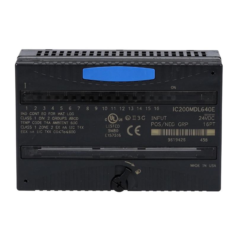
The GE IC200MDL640E VersaMax Discrete Input Module is a 24 V DC digital input module designed for the GE Fanuc VersaMax programmable logic controller (PLC) platform. It receives discrete signals from field devices and transfers their status to the controller for logic processing, equipment monitoring, and automated sequence control.
In industrial automation systems, discrete input modules provide the connection between field-level devices and PLC control logic. Sensors, pushbuttons, limit switches, and other switching devices generate signals representing conditions such as machine position, equipment status, operator commands, and process interlocks. The IC200MDL640E converts these electrical input states into digital information that can be processed by the VersaMax CPU or network interface unit.
This model provides 16 input points arranged in two groups of eight. It supports 24 V DC positive and negative logic, allowing the input groups to be wired according to the requirements of the connected field devices and control circuit design.
The IC200MDL640E is part of the VersaMax distributed I/O family. It receives operating power from the system backplane and requires a compatible carrier base for installation. Individual LED indicators show the status of the input points, while an OK indicator provides information about module backplane power.
With a basic input response time of 0.5 ms and configurable filtering options, the module can be used in a range of industrial monitoring and machine-control applications. Its role is to provide dependable digital signal acquisition between field devices and the PLC control system.
Technical Specifications
| Parameter | Specification |
|---|---|
| Brand | GE Fanuc / GE |
| Product Series | VersaMax |
| Model | IC200MDL640E |
| Product Type | Discrete Input Module |
| Input Type | Digital / Discrete Input |
| Number of Input Points | 16 |
| Input Groups | 2 groups of 8 |
| Nominal Input Voltage | 24 V DC |
| Input Voltage Range | 0–30 V DC |
| Logic Type | Positive and negative logic |
| On-State Voltage | 15–30 V DC |
| Off-State Voltage | 0–5 V DC |
| On-State Current | 2.0–5.5 mA |
| Off-State Current | 0–0.5 mA |
| Basic Input Response Time | 0.5 ms maximum |
| Configurable Input Filter | 0 ms, 1.0 ms, or 7.0 ms |
| Input Impedance | 10 kΩ maximum |
| Backplane Current Consumption | 25 mA maximum at 5 V DC |
| External Module Power Supply | Not required |
| LED Indicators | Individual input status LEDs and OK indicator |
| Isolation | Optical isolation between user inputs and logic; group isolation specified |
| Required Carrier | Compatible IC200CHS series carrier base |
| Dimensions Provided | 110 × 66.8 × 50 mm |
| Weight Provided | 0.45 kg |
| Mounting | VersaMax carrier-based installation |
Note: The dimensions and weight above are the supplied listing values. Confirm the complete hardware configuration and physical measurements before finalizing shipping or installation information.
Function and Working Principle
The IC200MDL640E receives electrical signals from field devices and converts their on/off states into digital input data for the VersaMax control system.
1. Digital Signal Acquisition
A discrete input represents one of two basic conditions: ON or OFF. For example, a proximity sensor may indicate whether a component is present, while a limit switch may indicate whether a mechanical assembly has reached a particular position.
The IC200MDL640E receives these 24 V DC signals through its input terminals. The module evaluates the electrical state of each channel and makes the corresponding digital information available to the PLC system.
The CPU or network interface unit processes the input information according to the application program.
2. Sixteen Input Channels
The module provides 16 discrete input points divided into two groups of eight.
This arrangement allows a single module to monitor several field devices while organizing the wiring into separate input groups. Each group has a common connection, which is used when wiring positive-logic or negative-logic input circuits.
For example, a machine may use several input points to monitor:
- Emergency-stop circuit status through an appropriate safety architecture.
- Motor contactor auxiliary contacts.
- Conveyor position switches.
- Proximity sensor signals.
- Equipment running feedback.
- Operator pushbuttons.
- Machine door or guard status signals.
The module itself is a standard digital input device and should not be treated as a safety-rated input module. Safety functions require appropriately certified safety equipment and circuit design.
3. Positive and Negative Logic
The IC200MDL640E supports positive and negative logic input arrangements.
In a positive-logic circuit, the input device supplies current to the input channel, with the current returning through the corresponding common connection.
In a negative-logic arrangement, the circuit uses the common connection to supply current toward the field device, which then returns the signal to the input channel.
The two groups of eight inputs can be wired according to the requirements of the application. Engineers should follow the module wiring diagram and verify the field device’s electrical characteristics before connecting signals.
4. Input Filtering
Industrial electrical environments may contain switching noise, short electrical disturbances, or mechanical contact bounce. These conditions can create unwanted signal transitions if they are not managed appropriately.
The IC200MDL640E provides configurable input filtering. The available filter settings are 0 ms, 1.0 ms, and 7.0 ms.
The basic input response time is 0.5 ms maximum. With additional filtering, the total response time increases. The documented total response times are approximately:
| Filter Setting | Total Response Time |
|---|---|
| 0 ms | 0.5 ms |
| 1.0 ms | 1.5 ms |
| 7.0 ms | 7.5 ms |
A shorter filter setting provides faster signal recognition, while a longer setting can help suppress unwanted transitions caused by electrical noise or switch bounce.
The appropriate value depends on the signal source and application requirements.
5. LED Status Indication
The module includes individual green LEDs for monitoring the ON/OFF status of each input point.
An additional OK LED indicates that backplane power is present at the module. These indicators help maintenance personnel identify input states during commissioning and troubleshooting.
LED indications should be interpreted together with the PLC program status and field wiring measurements. An illuminated input indicator does not necessarily confirm that the entire machine-control sequence is operating correctly.
Role in Industrial Control Systems
The IC200MDL640E serves as an input interface between field devices and the VersaMax PLC platform.
It does not independently execute the main machine-control program. Instead, it collects discrete signals and makes their status available to the CPU or network interface unit.
PLC System Integration
In a VersaMax control system, the IC200MDL640E is installed on a compatible carrier base. The module communicates with the controller through the system backplane.
The CPU reads the input states and uses them in programmed logic operations. These operations may include equipment sequencing, interlocking, alarm generation, motor control, and process monitoring.
For example, a PLC program may use an input signal from a limit switch to determine whether a machine actuator has reached its extended position. The controller can then allow the next stage of the production sequence to begin.
Sensor and Switch Connectivity
The module can receive signals from compatible 24 V DC field devices, including:
- Inductive proximity sensors.
- Photoelectric sensors.
- Mechanical limit switches.
- Pushbuttons and selector switches.
- Auxiliary relay contacts.
- Contactor feedback contacts.
- General-purpose machine status signals.
Before connecting any device, verify its output type, voltage, current, polarity, and wiring arrangement.
Distributed I/O Applications
VersaMax supports distributed I/O configurations in which input and output modules are installed near the equipment they serve.
In these installations, input signals can be collected locally and transferred through the control architecture to the main controller. This can help organize field wiring and simplify the arrangement of automation equipment across a production facility.
The IC200MDL640E can therefore be used in both compact machine-control panels and larger distributed automation systems, provided the carrier and controller configuration is compatible.
Industrial Applications
The 16-channel input capacity and 24 V DC signal interface make the IC200MDL640E suitable for a variety of general-purpose industrial monitoring and control applications.
1. Manufacturing Machinery
Manufacturing machines rely on discrete signals to identify equipment positions, operating states, and process conditions.
The module can collect signals from proximity sensors, limit switches, and operator controls. The PLC then uses this information to coordinate machine movements and production sequences.
Typical applications include assembly machines, material-feeding equipment, and automated workstations.
2. Conveyor and Material-Handling Systems
Conveyor systems use sensors and switches to detect product presence, belt position, transfer conditions, and equipment status.
The IC200MDL640E can collect these signals and provide them to the PLC for sequencing and monitoring.
For example, a photoelectric sensor may detect a product at a transfer point. The PLC can use the input state to control a downstream conveyor or activate another process step.
3. Packaging Equipment
Packaging machinery uses multiple discrete signals to monitor product position, package detection, machine doors, and actuator feedback.
The 16 input points allow several field devices to be connected to one module, subject to the electrical and wiring requirements of the installation.
The PLC can process these signals to coordinate feeding, sealing, cutting, and product-transfer operations.
4. Pumping and Auxiliary Equipment
Industrial pump systems often use discrete inputs to monitor motor contactors, pressure-switch status, tank-level switches, and equipment alarms.
The module can provide these states to the VersaMax controller, allowing programmed logic to coordinate equipment operation and generate alarms when abnormal conditions are detected.
5. Building and Utility Automation
In suitable control installations, the IC200MDL640E can monitor general-purpose switching signals from ventilation equipment, utility systems, and auxiliary machinery.
Examples include fan status, filter-switch indications, equipment running feedback, and general alarm contacts.
The electrical characteristics of each field device must be compatible with the module’s input specifications.
Installation and System Integration
Correct installation is essential for reliable signal acquisition and stable communication with the VersaMax controller.
1. Select a Compatible Carrier Base
The IC200MDL640E requires a compatible VersaMax carrier base from the IC200CHS series.
The carrier provides the mechanical mounting arrangement and electrical connection to the system backplane. Confirm the carrier model and terminal arrangement before installation.
The module should be installed and secured according to the applicable VersaMax hardware instructions.
2. Verify Input Voltage
The module is designed for nominal 24 V DC signals, with a specified input voltage range of 0–30 V DC.
Before connecting field devices, verify that their output voltage and current characteristics are suitable for the module.
Do not connect AC signals or voltage levels outside the module’s specified range.
3. Organize the Input Groups
The 16 input points are divided into two groups of eight. Each group has a common connection.
When designing the field wiring, identify which devices belong to each group and determine whether positive or negative logic is required.
The wiring arrangement should follow the manufacturer’s terminal diagram. Incorrect common connections or polarity can prevent signals from being detected correctly.
4. Configure Input Filtering
Select the input filter setting according to the characteristics of the connected field devices.
For fast electronic sensors, a shorter filter may be appropriate when rapid response is required. For mechanical contacts or signals affected by switching noise, additional filtering may improve signal stability.
The selected filter must not interfere with the timing requirements of the machine-control sequence.
5. Install and Check the Module
Before installation or removal, follow the system’s power-isolation and maintenance procedures.
After installation:
- Confirm that the module is seated correctly on its carrier.
- Inspect the field wiring and common connections.
- Verify the 24 V DC supply signals.
- Confirm that the OK indicator shows the expected status.
- Activate each field device and observe its corresponding input LED.
- Check the input state in the PLC programming environment.
- Test the relevant machine sequence and interlocks.
Record the final wiring and configuration information for future maintenance.
Compatible System Components
The IC200MDL640E is designed to operate within a compatible GE Fanuc VersaMax system.
| Component | Function | Integration Considerations |
|---|---|---|
| VersaMax CPU | Executes PLC logic and processes input data | Confirm the controller’s supported I/O configuration |
| VersaMax Network Interface Unit | Connects distributed I/O to the control network | Verify network architecture and module compatibility |
| IC200CHS Series Carrier Base | Provides mechanical mounting and backplane connection | Select a compatible carrier model |
| 24 V DC Power Supply | Supplies power to field input devices | Ensure adequate current capacity and correct polarity |
| Proximity Sensors | Detect the presence or position of objects | Confirm 24 V DC output compatibility |
| Photoelectric Sensors | Detect products and objects | Check output type and signal characteristics |
| Limit Switches | Provide mechanical position feedback | Verify contact ratings and wiring arrangement |
| Pushbuttons and Selector Switches | Provide operator input signals | Confirm contact configuration and common wiring |
| Relay Contacts | Provide auxiliary equipment status signals | Check contact condition and electrical ratings |
| PLC Programming Software | Configures and monitors the control application | Use a version compatible with the installed VersaMax controller |
The carrier base and field devices are not necessarily included with the IC200MDL640E module. Confirm the required system components separately when planning an installation or replacement.
Alternative Models and Replacement Considerations
When replacing an IC200MDL640E, the replacement must match the required input voltage, number of points, logic arrangement, carrier compatibility, and module revision requirements.
| Related Model | Product Description | Main Difference |
|---|---|---|
| IC200MDL640 | VersaMax 24 V DC, 16-point discrete input module | Base model in the same family |
| IC200MDL650 | VersaMax 24 V DC, 32-point discrete input module | Provides 32 input points rather than 16 |
| IC200MDL643 | VersaMax 5/12 V DC TTL input module | Uses a different input voltage range |
| IC200MDL644 | VersaMax 5/12 V DC TTL, 32-point input module | Different voltage class and point count |
| IC200MDL635 | VersaMax 48 V DC discrete input module | Designed for a different input voltage range |
| IC200MDL636 | VersaMax 48 V DC, 32-point input module | Different voltage class and point count |
These models are related VersaMax input modules, not automatic substitutes.
Before selecting a replacement, verify:
- Input voltage and signal type.
- Number of input channels.
- Positive-logic or negative-logic requirements.
- Input grouping and common-terminal arrangement.
- Input response time and filter settings.
- Carrier-base compatibility.
- Module revision and system configuration.
- PLC hardware and software support.
A 32-point module may appear to offer more capacity, but it can have different wiring and configuration requirements. A module with a different voltage class should not be substituted without redesigning the relevant field interface.
Key Advantages
Sixteen Discrete Input Channels
The module provides 16 input points in a compact VersaMax format, allowing several field devices to be monitored through one module.
24 V DC Signal Compatibility
Its 24 V DC input design supports common industrial sensors, switches, and contact-based signals.
Positive and Negative Logic
The two groups of eight inputs can support positive-logic and negative-logic wiring arrangements, providing flexibility for different field-device circuits.
Fast Input Response
The basic input response time is 0.5 ms maximum, supporting applications that require relatively fast recognition of input-state changes.
Configurable Filtering
Selectable filter times allow engineers to balance signal response speed and resistance to unwanted switching transitions.
Individual LED Indicators
Each input point has an LED for local status monitoring. The OK indicator provides an additional indication of backplane power status.
VersaMax System Integration
The module is designed for the GE Fanuc VersaMax platform and can be incorporated into compatible PLC and distributed I/O installations.
Technical FAQs
1. What is the GE IC200MDL640E?
The IC200MDL640E is a GE Fanuc VersaMax discrete input module designed to receive 24 V DC digital signals from industrial field devices and transfer their status to the PLC control system.
2. How many input channels does it provide?
It provides 16 discrete input points arranged in two groups of eight.
3. What is the nominal input voltage?
The nominal input voltage is 24 V DC, with a specified input range of 0–30 V DC.
4. Does the module support positive and negative logic?
Yes. The module supports positive-logic and negative-logic input arrangements. Each group of eight inputs has a common connection, and wiring must follow the manufacturer’s instructions.
5. What is the input response time?
The basic input response time is 0.5 ms maximum. Additional software-configurable filtering can increase the total response time.
6. Does it require an external power supply?
The module’s operating power is supplied through the VersaMax backplane. It does not require a separate external module power supply. However, compatible 24 V DC power must be provided to field devices where their electrical design requires it.
7. Does the IC200MDL640E require a carrier base?
Yes. It requires a compatible VersaMax carrier base, such as an appropriate model from the IC200CHS series.
8. How can technicians check input status?
Each input point has an individual LED indicator. Technicians can also monitor the corresponding input states through the PLC programming and diagnostic environment.
9. Can the IC200MDL640E be replaced by an IC200MDL650?
Not automatically. The IC200MDL650 provides 32 input points, compared with the 16 points on the IC200MDL640E. The wiring, configuration, and system requirements should be checked before substitution.
10. Is this module suitable for safety-critical emergency-stop circuits?
The IC200MDL640E is a standard discrete input module, not a dedicated safety-rated input module. Safety-related functions must use appropriately certified safety controllers, input modules, and circuit architectures.
Procurement and Maintenance Recommendations
When purchasing the GE IC200MDL640E, verify the complete model number, hardware revision, and physical condition. The suffix E is part of the product identification and should be checked against the installed module.
For replacement projects, confirm that the existing VersaMax carrier, CPU or network interface unit, field wiring, and PLC configuration support the selected module.
If purchasing used or refurbished equipment, request clear photographs of the model label, terminal area, housing, and connector surfaces. Where possible, obtain functional test information showing that the module powers up and correctly detects input signals.
During maintenance, inspect the carrier connection, field terminals, wiring insulation, and common connections. Check the input LEDs against the actual field-device states and compare them with the PLC input data. Unexpected signal changes may result from wiring problems, incorrect polarity, unstable field-device outputs, or unsuitable filtering.
Keep a record of the input assignments, group wiring, filter settings, and PLC addresses. This information can reduce troubleshooting time and help ensure that replacement modules are configured consistently.
Conclusion
The GE IC200MDL640E VersaMax Discrete Input Module is a 24 V DC, 16-point digital input module designed for industrial PLC and distributed I/O applications. Its two groups of eight inputs support positive-logic and negative-logic wiring, while its 0.5 ms basic response time and configurable input filtering provide flexibility for different signal-monitoring requirements.
With individual input LEDs, backplane-powered operation, and compatibility with the VersaMax carrier-based architecture, the IC200MDL640E provides a practical interface between industrial field devices and PLC control logic.
For maintenance and replacement applications, engineers should verify the complete model number, input characteristics, carrier compatibility, and wiring arrangement before installation.