

ProductPRODUCT
Featured products
Contact Us
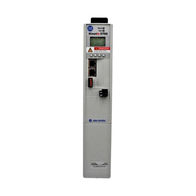
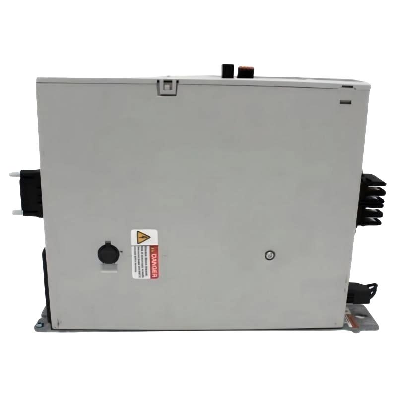
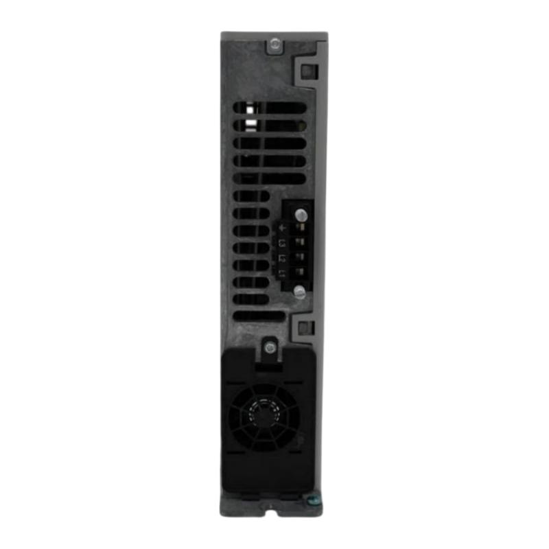
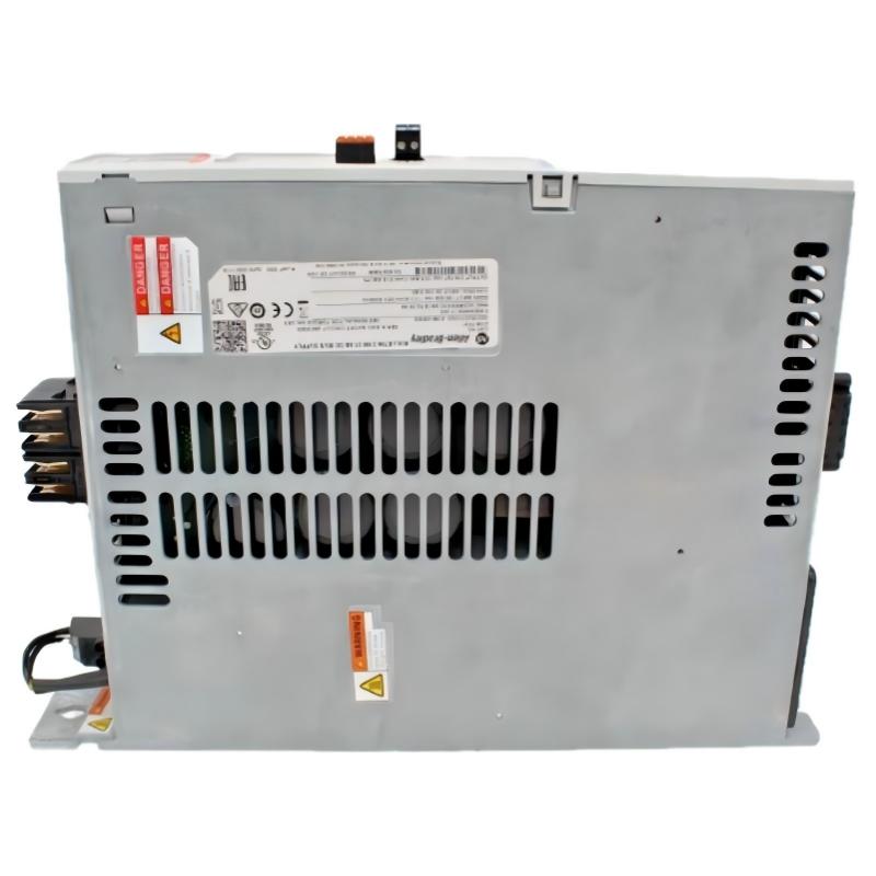
- Allen Bradley
- 2198-P031
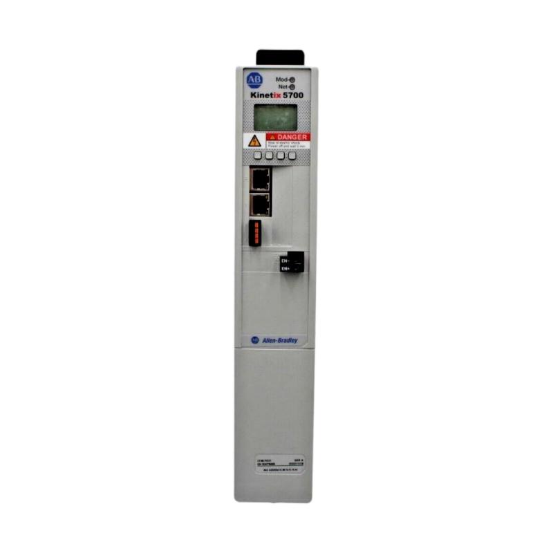
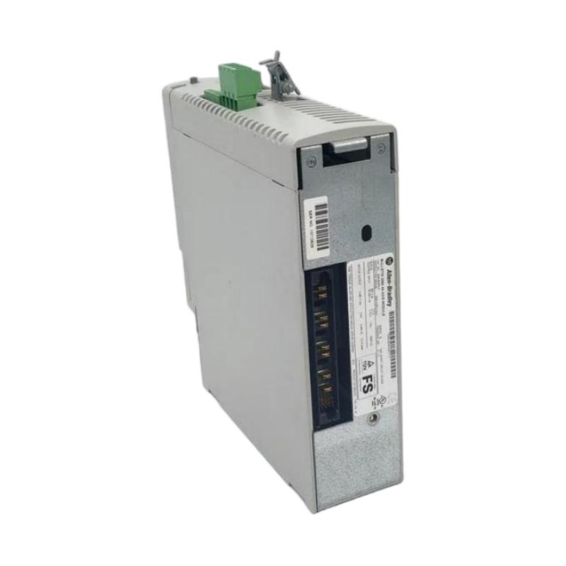
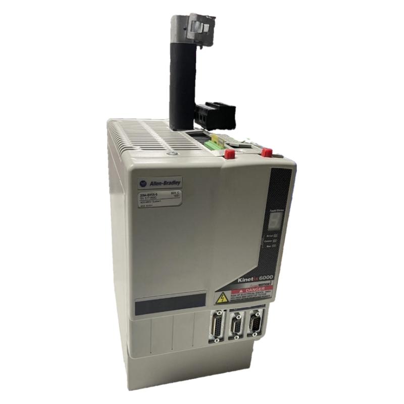
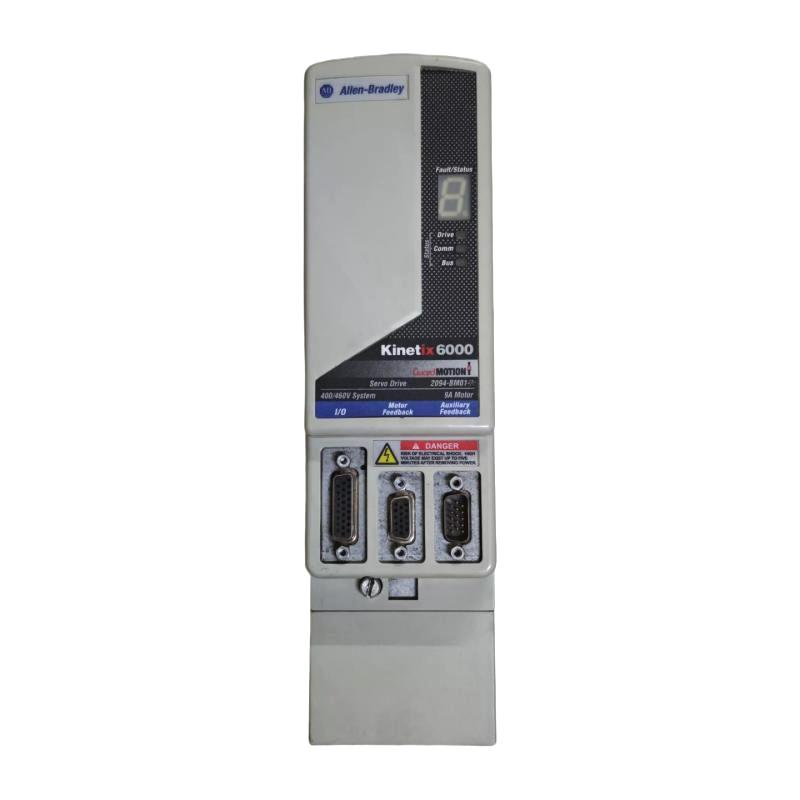
- Kinetix 5700 DC Bus Power Supply
- USA
- 358 x 300 x 55 mm
- 4.33 kg
- Xiamen, China
- New & In Stock
- T/T, PayPal, Western Union
- 1 Year
- 1-3 Working Days
- DHL, UPS, TNT, FedEx and EMS.
- 24-Hour Service
- COO
- 3
Our advantage

Global Logistics
We have a 10-year logistics and express cooperation agreement, so our products can be shipped to any place in the world.

Brand new and original
Our products are imported in bulk from the place of origin. Because of the cooperative relationship, our products are all original and 100% new.

24-hour service
We provide 7*24 hours service to our customers. We will be there whenever you need us.

Price advantage
All our products are priced very favorably because we have our own warehouse and supply.
| Company Information | |||
| [email protected] | |||
| Mobile | +8615980777398 | ||
| +8615980777398 | |||
| 15980777398 |
Product Overview
The Allen-Bradley 2198-P031 Kinetix 5700 DC Bus Power Supply is a power-conversion module designed for Rockwell Automation’s Kinetix 5700 servo drive system. It provides the DC-bus power required by connected servo inverters, supporting coordinated motion control in industrial automation applications.
Manufactured by Allen-Bradley, a brand of Rockwell Automation, the 2198-P031 is part of the Kinetix 5700 modular servo drive platform. This platform is designed for multi-axis motion applications that require reliable power distribution, precise motor control, and integration with programmable automation controllers.
The primary function of the 2198-P031 is to convert incoming three-phase AC electrical power into DC-bus power. The resulting DC voltage is distributed through the shared DC-bus system to compatible inverter modules, which control the operation of connected servo motors.
The module supports a continuous DC-bus output current of 10.5 A and a continuous output power rating of 7 kW under the specified operating conditions. Its input voltage range is 195–528 V AC, three-phase, making it suitable for compatible 240 V and 480 V-class power systems.
Unlike a conventional standalone power supply, the 2198-P031 is designed specifically for integration into a modular servo drive architecture. It works together with Kinetix 5700 inverter modules, DC-bus components, control power connections, and industrial automation controllers.
For machine builders and maintenance engineers, this module provides an important power-conversion component for multi-axis servo systems used in packaging, material handling, manufacturing, and other automated production processes.
Technical Specifications
| Parameter | Specification |
|---|---|
| Brand | Allen-Bradley |
| Manufacturer | Rockwell Automation |
| Model | 2198-P031 |
| Product Series | Kinetix 5700 |
| Product Type | DC Bus Power Supply |
| Module Function | AC-to-DC Bus Power Conversion |
| Input Voltage | 195–528 V AC |
| Input Phase | Three-phase |
| Input Frequency | 47–63 Hz |
| Nominal Supply Classes | 240 V / 480 V |
| Continuous Output Power | 7 kW |
| Continuous DC-Bus Output Current | 10.5 A |
| Peak DC-Bus Output Current | Approximately 31.6 A |
| Peak Current Duration | Up to 1 second, subject to duty-cycle limits |
| Nominal DC-Bus Voltage Range | 276–747 V DC |
| Control Power Input | 24 V DC ±10% |
| Control Power Current | Approximately 0.8 A DC |
| Module Width | 55 mm |
| Dimensions Provided | 358 × 300 × 55 mm |
| Weight Provided | 4.33 kg |
| Compatible Platform | Kinetix 5700 Servo Drive System |
| Typical Applications | Multi-axis servo motion control |
Note: Electrical ratings depend on the supply voltage and operating conditions. The supplied dimensions and weight are retained as listing information. Confirm the exact physical dimensions and shipping weight against the actual unit before installation or transportation.
Function and Working Principle
The 2198-P031 performs the AC-to-DC power conversion required by the Kinetix 5700 servo drive system. It supplies a shared DC bus that distributes electrical energy to compatible inverter modules.
1. AC Input Power Conversion
The module receives three-phase AC power from the industrial electrical distribution system. Its power-conversion circuitry processes the incoming electrical supply and produces DC power for the servo system.
The supported input voltage range is 195–528 V AC, three-phase. This allows the module to operate in compatible 240 V and 480 V-class installations.
Correct input voltage selection, circuit protection, grounding, and wiring are essential for safe and reliable operation.
2. DC-Bus Power Distribution
After conversion, DC power is supplied to the shared DC bus. Compatible Kinetix 5700 inverter modules connect to this bus and use the available electrical energy to control their associated servo motors.
This modular arrangement allows multiple servo axes to operate within one coordinated drive system.
The 2198-P031 provides a continuous DC-bus output current of 10.5 A and a continuous output power rating of 7 kW. These ratings must be considered when calculating the total power demand of the connected servo axes.
3. Peak Current Capability
Servo systems may experience temporary increases in power demand during acceleration, deceleration, and changes in mechanical load.
The 2198-P031 supports a peak DC-bus output current of approximately 31.6 A for up to one second, subject to the specified duty-cycle restrictions.
Engineers should evaluate both continuous and peak power requirements when designing a servo system. A power supply should not be selected solely according to the sum of motor nameplate power ratings.
4. 24 V DC Control Power
In addition to the main AC input, the module uses a 24 V DC control power supply. This control power supports the required control circuitry independently of the main power-conversion function.
The specified control power input is 24 V DC ±10%. The control power supply must have sufficient capacity for the connected system and should be wired according to the manufacturer’s instructions.
5. Shared Energy Architecture
The Kinetix 5700 system uses a shared DC-bus architecture. This arrangement allows compatible inverter modules to draw power from a common DC-bus source.
In suitable applications, energy generated by decelerating servo axes may be available to other axes through the shared DC-bus architecture, subject to system configuration and operating conditions.
This approach can help simplify power distribution in multi-axis machinery compared with designing every servo axis as a completely independent drive system.
Role in Industrial Automation Systems
The 2198-P031 is an important power component within a Kinetix 5700 servo motion-control system. It provides the electrical foundation required by the inverter modules that directly control servo motors.
1. Integration with Servo Inverter Modules
The DC-bus power supply connects to compatible Kinetix 5700 inverter modules through the system’s shared bus arrangement.
The inverter modules use the DC-bus power to generate controlled motor output. This allows servo motors to perform precise movements according to the commands issued by the motion controller.
The number and type of inverter modules must be selected according to the available DC-bus capacity and the system’s electrical requirements.
2. Integration with PLC and Motion Controllers
The Kinetix 5700 platform can be integrated with Rockwell Automation control systems, including suitable ControlLogix and CompactLogix controllers.
The controller executes the machine logic and motion commands, while the servo drive system supplies the electrical power and motor-control functions.
A typical system may include:
- ControlLogix or CompactLogix controller.
- Kinetix 5700 DC-bus power supply.
- Compatible Kinetix 5700 inverter modules.
- Servo motors and feedback devices.
- EtherNet/IP communication infrastructure.
- Safety and emergency-stop circuits.
- Industrial power distribution and protective devices.
The exact configuration depends on the machine’s axis count, motor requirements, safety architecture, and communication design.
3. Multi-Axis Motion Coordination
Industrial machines often require multiple motors to operate in coordination. Examples include packaging lines, robotic handling equipment, and synchronized production machinery.
The 2198-P031 supplies the DC-bus power needed by compatible inverter modules, allowing the servo system to support coordinated movement across multiple axes.
The motion controller manages the movement commands, while the power supply provides the required electrical energy.
4. Power Distribution and System Reliability
A properly designed DC-bus power architecture helps organize electrical power distribution across the servo system.
The power supply must be matched to the connected inverter modules and the expected operating profile. Engineers should evaluate continuous power demand, peak current, input supply conditions, and system protection before commissioning.
Industrial Applications
The Allen-Bradley 2198-P031 is designed for Kinetix 5700 servo systems used in industrial automation and motion-control applications.
1. Packaging Machinery
Packaging equipment frequently requires several servo axes to operate in synchronization. These axes may control product feeding, film handling, cutting, sealing, and indexing operations.
The 2198-P031 supplies DC-bus power to compatible servo inverters, supporting the coordinated motor operation required by automated packaging systems.
2. Material Handling Systems
Automated material-handling equipment may use servo motors for positioning, transfer, lifting, and synchronized movement.
The Kinetix 5700 platform can support these applications when the motor and inverter configuration meets the required load and motion specifications.
The DC-bus power supply provides the common electrical source for the connected inverter modules.
3. Automated Assembly Lines
Assembly machines often require accurate positioning and repeatable movement. Servo-driven mechanisms may control pressing, insertion, indexing, and product transfer operations.
The 2198-P031 supports the power requirements of compatible servo drive systems used in these applications.
4. Printing and Converting Equipment
Printing and converting machinery may require synchronized motor operation to maintain material tension, registration, and production speed.
A multi-axis servo system can coordinate the operation of rollers, feeding mechanisms, and cutting units. The DC-bus power supply provides electrical power to the connected inverter modules.
5. Robotics and Automated Production Equipment
Industrial automation systems may use servo-driven mechanisms for positioning, handling, and coordinated movement.
The Kinetix 5700 architecture can be incorporated into suitable motion-control systems where the required axis performance, electrical ratings, and controller compatibility are satisfied.
6. General Manufacturing Machinery
The 2198-P031 may also be used in manufacturing equipment that requires multiple servo axes, including automated processing machines, indexing equipment, and specialized production systems.
Its suitability depends on the combined electrical requirements of the connected servo inverters and motors.
Installation and System Integration
Correct installation is essential for safe operation and reliable DC-bus power distribution.
1. Verify the Input Power Supply
Before installation, confirm that the incoming electrical supply is within the module’s supported range of 195–528 V AC, three-phase.
Check the supply frequency, phase configuration, grounding arrangement, and upstream protective devices.
The input power system must comply with the manufacturer’s recommendations and applicable electrical regulations.
2. Check the Control Power Supply
The 2198-P031 requires a separate 24 V DC control power input.
Verify that the control power supply provides the required voltage and sufficient current capacity. Incorrect control power wiring can prevent the servo system from starting or cause unexpected faults.
3. Mounting and Panel Installation
The supplied dimensions are 358 × 300 × 55 mm, with a listed weight of 4.33 kg.
The manufacturer’s technical documentation identifies the module width as 55 mm. Before designing the electrical cabinet, verify the complete dimensional drawing, mounting positions, and required clearances.
The module should be installed in an appropriate industrial enclosure with sufficient ventilation and space for electrical connections.
Avoid installing the equipment in locations exposed to excessive moisture, conductive dust, or corrosive substances unless suitable environmental protection is provided.
4. DC-Bus Connection
The DC-bus power supply must be connected to compatible Kinetix 5700 inverter modules using the designated system bus arrangement.
Ensure that all bus connections are correctly installed and that the required end caps and accessories are fitted.
Incorrect bus connections can result in electrical faults, equipment damage, or unsafe operating conditions.
5. Grounding and Electrical Protection
Grounding is an important part of the installation process.
The correct grounding configuration depends on the site’s electrical distribution system. Rockwell Automation provides specific instructions for grounded-wye, ungrounded, corner-grounded, and impedance-grounded power configurations.
Upstream circuit protection must be selected according to the applicable manufacturer tables and local electrical requirements.
6. Commissioning and Testing
After installation, inspect the power connections, control wiring, grounding, and DC-bus connections.
Before enabling the system, verify that the connected inverter modules and motors are compatible with the power supply.
During commissioning, check:
- AC input voltage and phase sequence.
- 24 V DC control power.
- DC-bus connections and polarity.
- Protective grounding.
- Inverter module configuration.
- Controller communication.
- Servo enable and fault conditions.
- System response under expected operating loads.
All commissioning work should be performed by qualified personnel following the manufacturer’s safety instructions.
Compatible System Components
The 2198-P031 is designed to operate as part of the Kinetix 5700 modular servo drive system.
| Component | Function | Integration Considerations |
|---|---|---|
| Kinetix 5700 inverter modules | Convert DC-bus power into controlled motor output | Verify inverter compatibility and combined power demand |
| Kinetix servo motors | Provide mechanical movement | Match motor ratings, feedback, and application requirements |
| ControlLogix controller | Executes machine and motion-control logic | Confirm controller and motion-system compatibility |
| CompactLogix controller | Provides automation and motion control | Verify supported controller and firmware configuration |
| 24 V DC power supply | Provides control power | Confirm voltage and current capacity |
| EtherNet/IP network | Supports controller and drive communication | Configure network topology and communication settings |
| DC-bus accessories | Support bus connections and system arrangement | Use compatible components and installation procedures |
| Circuit protection devices | Protect the incoming power circuit | Follow the manufacturer’s protection recommendations |
| Industrial control cabinet | Houses and protects the servo system | Provide adequate cooling and installation clearances |
These components are examples of equipment used in a complete Kinetix 5700 system. They are not necessarily included with the 2198-P031 power supply.
Alternative Models and Replacement Considerations
The Kinetix 5700 product family includes several DC-bus power supply models. These models have different output power and current ratings.
| Model | Continuous Output Power | Continuous DC-Bus Current | Module Width |
|---|---|---|---|
| 2198-P031 | 7 kW | 10.5 A | 55 mm |
| 2198-P070 | 17 kW | 25.5 A | 85 mm |
| 2198-P141 | 31 kW | 46.9 A | 85 mm |
| 2198-P208 | 46 kW | 69.2 A | 85 mm |
The models above belong to the same product family, but they are not automatically interchangeable.
When replacing a 2198-P031, engineers should evaluate:
- Input voltage and three-phase supply requirements.
- Continuous DC-bus current.
- Continuous output power.
- Peak current requirements.
- Connected inverter module configuration.
- Available cabinet space and module width.
- Control power requirements.
- Grounding and circuit-protection arrangements.
- System firmware and controller compatibility.
- Required accessories and DC-bus connections.
A higher-capacity power supply should not be selected solely because it provides more output power. The complete system configuration must remain compatible with the selected module.
Key Advantages
1. Dedicated Kinetix 5700 Integration
The 2198-P031 is designed specifically for the Kinetix 5700 platform, providing the DC-bus power required by compatible servo inverter modules.
2. Three-Phase AC Input
Its 195–528 V AC three-phase input range supports compatible industrial electrical distribution systems.
3. 7 kW Continuous Output Power
The module provides a continuous output power rating of 7 kW under the specified operating conditions, supporting appropriately configured servo systems.
4. Shared DC-Bus Architecture
The common DC-bus arrangement supports modular multi-axis drive configurations and organized power distribution.
5. Peak Current Capability
The module supports temporary peak output current for demanding servo operating conditions, subject to the manufacturer’s limits.
6. Separate Control Power
The 24 V DC control power input provides a dedicated supply for the module’s control circuitry.
7. Modular System Design
The Kinetix 5700 platform allows engineers to configure servo systems using compatible power supplies, inverter modules, and system accessories.
Technical FAQs
1. What is the Allen-Bradley 2198-P031?
The 2198-P031 is a Kinetix 5700 DC-bus power supply manufactured by Rockwell Automation. It converts three-phase AC input power into DC-bus power for compatible servo inverter modules.
2. What input voltage does the 2198-P031 support?
It supports an input range of 195–528 V AC, three-phase, with an input frequency of 47–63 Hz.
3. What is the continuous output power?
The module has a continuous output power rating of 7 kW under the specified operating conditions.
4. What is its continuous DC-bus output current?
The continuous DC-bus output current is 10.5 A.
5. Does the 2198-P031 require a separate 24 V DC supply?
Yes. The module uses a 24 V DC control power input, specified at ±10%.
6. Can the 2198-P031 power multiple servo axes?
Yes. It is designed to provide DC-bus power to compatible Kinetix 5700 inverter modules. The number and type of axes depend on the total power demand and system configuration.
7. Is the 2198-P031 a servo amplifier?
It is a DC-bus power supply rather than an individual motor inverter. The connected inverter modules perform the motor-control function.
8. What is the module width?
The manufacturer specifies a module width of 55 mm.
9. Is the 2198-P031 compatible with other Kinetix 5700 power supply models?
It belongs to the same product family as the 2198-P070, 2198-P141, and 2198-P208. However, these models have different power and current ratings. They should only be substituted after a complete system compatibility assessment.
10. What should be checked before purchasing a replacement?
Verify the complete catalog number, nameplate information, physical condition, electrical ratings, and included connectors or accessories. For used equipment, request photographs and available functional test information.
Procurement and Maintenance Recommendations
When purchasing the Allen-Bradley 2198-P031, confirm the complete model number and ensure that it matches the requirements of the existing Kinetix 5700 servo system.
Check the input voltage range, continuous output power, DC-bus current, control power requirements, and connected inverter configuration. These details are important because a mismatch can affect system operation and equipment protection.
For new, surplus, or refurbished modules, request clear photographs of the product label, terminal areas, and physical enclosure. Confirm the product condition, testing status, warranty terms, and whether the required connectors and accessories are included.
During routine maintenance, inspect electrical connections, grounding, cabinet ventilation, and the condition of connected bus components. Look for signs of overheating, loose terminals, contamination, or physical damage.
Before servicing the module, isolate the incoming power and follow the manufacturer’s discharge procedures. DC-bus capacitors may retain hazardous voltage after the AC supply has been disconnected. Wait the specified time and verify that the DC bus is discharged before touching electrical connections.
For long-term equipment management, keep records of the installed catalog number, system configuration, firmware information, and replacement history. These records help maintenance teams identify compatible spare parts and reduce unnecessary commissioning work.
Conclusion
The Allen-Bradley 2198-P031 Kinetix 5700 DC Bus Power Supply is an important power-conversion component for industrial multi-axis servo systems. It accepts 195–528 V AC three-phase input and provides 7 kW of continuous output power with a 10.5 A continuous DC-bus current rating.
Designed for integration with compatible Kinetix 5700 inverter modules, the 2198-P031 supports shared DC-bus power distribution in packaging machinery, material-handling systems, automated assembly equipment, and other motion-control applications.
For industrial maintenance, procurement, and replacement projects, verifying the complete model number, electrical ratings, control power requirements, and system configuration is essential for maintaining reliable servo system operation.