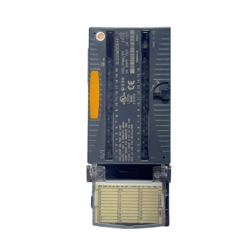
Product Overview
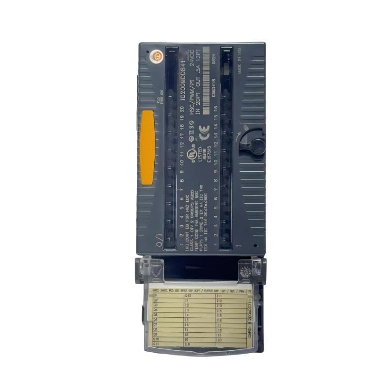
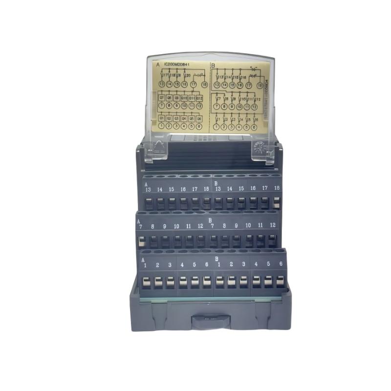
The GE IC200MDD841 VersaMax High-Speed Counter Module is a specialized I/O module designed for GE VersaMax industrial automation systems that require high-speed counting and pulse-based signal processing.
Standard PLC digital inputs are suitable for many conventional ON/OFF signals, but high-speed machine applications can require signal detection at frequencies or rates where normal PLC scan-based processing may not provide the required response. A high-speed counter module addresses this requirement by providing dedicated hardware for monitoring rapid pulse signals and counting events independently of the normal application-program scan.
The IC200MDD841 is therefore particularly relevant to applications involving rotating equipment, incremental encoders, production counters, position detection and other systems where pulse frequency or accumulated counts represent an important machine parameter.
The module can be used as an interface between high-speed field devices and the VersaMax control system. Depending on the application, pulse information can be used to determine machine speed, position, quantity, rotational movement or production rate.
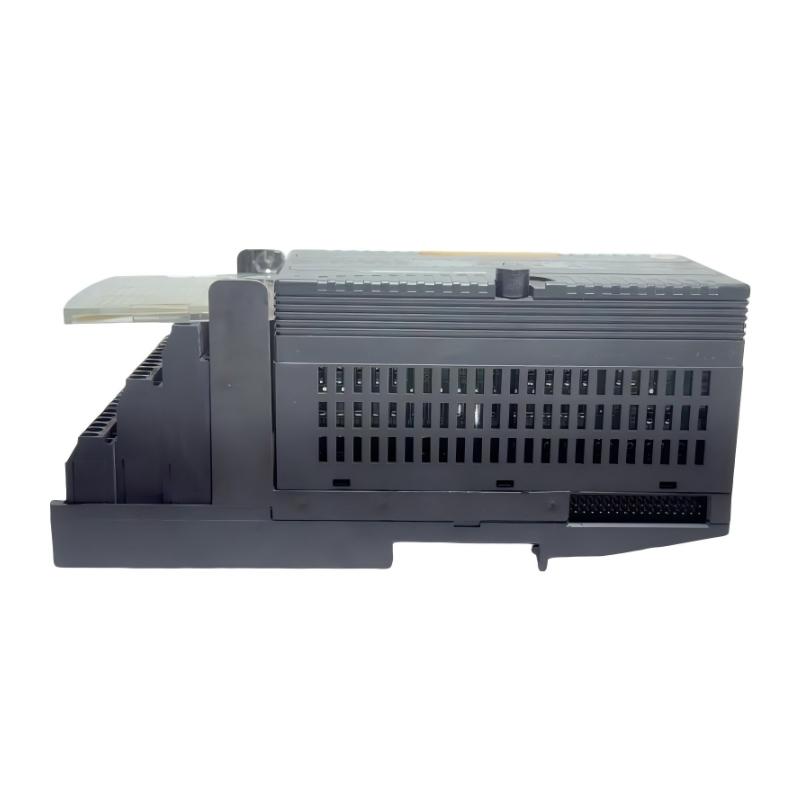
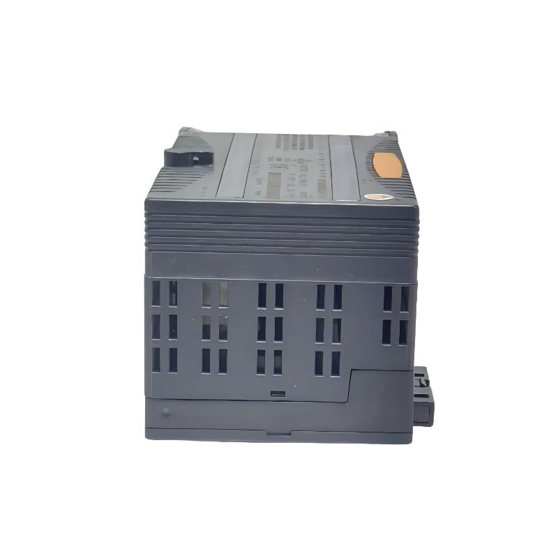
The specified dimensions of the IC200MDD841 are 133.4 × 85.9 × 69.1 mm, with a weight of approximately 0.159 kg. Its compact industrial form factor makes it suitable for installation within VersaMax control cabinets and machine-control panels.
Technical Specifications
| Parameter |
Details |
| Manufacturer |
GE / GE Fanuc |
| Product Series |
VersaMax |
| Model |
IC200MDD841 |
| Product Type |
High-Speed Counter Module |
| Main Function |
High-speed pulse counting |
| Application |
High-speed machine monitoring and control |
| Signal Type |
Pulse / high-speed discrete signals |
| Dimensions |
133.4 × 85.9 × 69.1 mm |
| Weight |
0.159 kg |
| Installation |
VersaMax modular I/O system |
| Measurement Function |
Pulse counting and high-speed event detection |
| Typical Inputs |
Encoder and pulse-generating devices |
| Application Type |
Machine and motion-related automation |
| System Architecture |
Modular PLC / distributed I/O |
| Controller Relationship |
Interfaces high-speed signals with VersaMax control |
| Maintenance |
Modular I/O replacement |
| Environment |
Industrial control cabinet |
| Mounting |
VersaMax system-dependent installation |
Function and Working Principle
The primary function of the IC200MDD841 is to detect and count high-speed pulse signals that may be generated by industrial sensors or rotating equipment.
A conventional PLC input is normally evaluated as part of the controller’s scanning process. When a machine generates pulses rapidly, relying only on the normal PLC scan can make accurate pulse detection more difficult.
A dedicated high-speed counter module provides a specialized interface for these signals.
A simplified signal path is:
Pulse-Generating Device → IC200MDD841 → VersaMax Control System
The module detects the incoming pulse events and maintains the corresponding count information for use by the control application.
Pulse Counting
Many industrial devices produce a sequence of electrical pulses as they operate.
For example, an incremental encoder can generate pulses as a shaft rotates:
Encoder Rotation → Pulse Signal → IC200MDD841 → Counter Value
The controller can then use the count information to determine machine movement or production conditions.
Frequency-Based Monitoring
Pulse frequency can also provide information about machine speed.
A simplified relationship is:
Pulse Frequency → IC200MDD841 → Control System → Speed Calculation
For example, a rotating shaft may generate a known number of pulses per revolution. By measuring the pulse rate, the control system can determine rotational speed.
The exact calculation depends on the encoder or sensor characteristics and the application configuration.
Role in Industrial Control Systems
The IC200MDD841 provides a dedicated interface for high-speed pulse signals within a VersaMax automation architecture.
A typical system may contain:
Encoder / Pulse Sensor
↓
IC200MDD841
↓
VersaMax CPU
↓
Machine Control Logic
The high-speed counter information can be used by the PLC program for tasks such as:
- Position monitoring
- Speed monitoring
- Product counting
- Length measurement
- Machine-cycle monitoring
- Rotational monitoring
- Production counting
This makes the module particularly valuable for machinery where timing and pulse accuracy are important.
Industrial Applications
The GE IC200MDD841 can be used in a variety of high-speed automation applications.
Typical applications include:
- Conveyor systems
- Packaging machinery
- Printing equipment
- Material handling
- Rotary machinery
- Production counting
- Encoder-based position monitoring
- Speed monitoring
- Cutting machinery
- Assembly machines
- Filling equipment
- Winding systems
- Machine tools
- Manufacturing automation
- OEM equipment
Production Counting
In a packaging or manufacturing line, each product may generate a pulse when it passes a sensor.
The sequence can be:
Product Detection → Pulse → IC200MDD841 → Count Accumulation → PLC Logic
The PLC can use the accumulated count to control production sequences, batch quantities or machine stops.
Rotational Speed Monitoring
A rotating shaft fitted with a pulse-generating sensor can provide a continuous stream of pulses.
The system can use this information to monitor:
- Shaft speed
- Motor rotation
- Conveyor speed
- Machine-cycle rate
- Equipment operation
This allows the PLC to detect abnormal speed conditions or coordinate other machine operations.
High-Speed Counter vs. Standard Digital Input
The IC200MDD841 should not be considered simply another standard digital input module.
| Feature |
IC200MDD841 |
Standard Digital Input |
| Main Function |
High-speed pulse counting |
Discrete signal monitoring |
| Typical Signal |
Rapid pulse train |
ON/OFF signal |
| Primary Application |
Speed, position and counting |
Switch and sensor monitoring |
| Pulse Processing |
Dedicated counting function |
Normal PLC input processing |
| Suitable for High-Speed Signals |
Yes |
Application-dependent |
| Typical Devices |
Encoders, pulse sensors |
Switches, proximity sensors |
| Main Measurement |
Count / pulse rate |
State |
This distinction is important when selecting hardware for machines with rapidly changing pulse signals.
Encoder and Pulse-Signal Applications
One of the important applications for a high-speed counter is encoder signal processing.
An encoder can produce pulses corresponding to mechanical movement.
For example:
Mechanical Rotation
↓
Encoder
↓
Pulse Train
↓
IC200MDD841
↓
PLC Control Application
The accumulated pulse count can represent a relative mechanical position, while pulse frequency can provide information related to rotational speed.
In a conveyor system, for example, encoder pulses can be used to monitor conveyor movement and coordinate downstream operations.
Position Monitoring
Pulse counting can also be used for relative position measurement.
If the machine uses a device that produces a known number of pulses per unit of movement, the control system can relate the accumulated pulse count to mechanical displacement.
A simplified concept is:
Pulse Count × Mechanical Scaling Factor = Estimated Position
The scaling factor depends on the mechanical system, encoder characteristics and application configuration.
This approach can be used in:
- Cutting machines
- Conveyor positioning
- Packaging equipment
- Winding machinery
- Material handling
- Assembly equipment
The exact positioning accuracy depends on the complete mechanical and control-system design.
Installation and System Integration
Correct installation is particularly important for high-speed signal applications because electrical noise and poor wiring can affect pulse detection.
Mechanical Installation
Before installation, verify:
- Correct model
- Compatible VersaMax system
- Appropriate module position
- Adequate cabinet space
- Suitable environmental conditions
- Proper mechanical engagement
The specified dimensions are 133.4 × 85.9 × 69.1 mm, so sufficient clearance should be provided.
Signal Wiring
High-speed pulse signals should be wired carefully.
Important considerations include:
- Secure connections
- Correct signal polarity where applicable
- Appropriate cable selection
- Proper cable routing
- Separation from high-power conductors
- Minimization of electrical noise
- Correct shielding practices where required
High-speed signals can be more sensitive to electrical interference than slow-changing digital signals.
Encoder Integration
When connecting an encoder or pulse-generating sensor, verify:
- Signal compatibility.
- Wiring configuration.
- Pulse characteristics.
- Mechanical installation.
- Encoder direction requirements.
- Control-system configuration.
The encoder and high-speed counter should be treated as a complete measurement chain.
Commissioning
A practical commissioning procedure includes:
- Install the IC200MDD841.
- Verify mechanical installation.
- Connect the pulse-generating device.
- Check signal wiring.
- Verify the VersaMax configuration.
- Start the system.
- Generate a controlled pulse signal.
- Verify counter operation.
- Compare the measured count with the expected value.
- Test the application at operating speed.
Compatible System Components
The IC200MDD841 is normally integrated into a complete VersaMax automation system.
| Component |
Function |
| VersaMax CPU Module |
Executes PLC application logic |
| VersaMax Power Module |
Supports system power |
| IC200MDD841 |
Processes high-speed pulse-counting signals |
| Incremental Encoder |
Generates pulses based on movement |
| Pulse Sensor |
Generates high-speed discrete signals |
| Proximity Sensor |
Detects machine movement or objects |
| I/O Carrier |
Provides module interface |
| Terminal Base |
Supports field wiring |
| Ethernet Interface |
Provides network communication where required |
| Drive / Motor System |
Provides machine movement |
| Mechanical Transmission |
Converts motor rotation into machine movement |
The actual components depend on the machine’s measurement and control requirements.
High-Speed Counting in Conveyor Systems
A conveyor is a common example of an application where high-speed counting can be useful.
An encoder connected to the conveyor shaft can generate pulses as the conveyor moves.
The control sequence can be represented as:
Conveyor Movement → Encoder Pulses → IC200MDD841 → PLC → Conveyor Control
The system can use pulse information to estimate:
- Conveyor movement
- Speed
- Product spacing
- Production count
- Machine position
For example, the PLC may use pulse counts to coordinate a product-detection sensor with a downstream actuator.
This allows machine operations to be synchronized according to actual mechanical movement rather than relying solely on elapsed time.
High-Speed Counter Troubleshooting
When the IC200MDD841 does not count pulses correctly, troubleshooting should cover the entire signal path.
A practical sequence is:
Power → Sensor / Encoder → Wiring → IC200MDD841 → Configuration → PLC Application
Check the Pulse Source
Verify that the encoder or pulse-generating sensor is actually producing the expected signal.
A defective sensor can appear to be a module problem.
Check Signal Wiring
Inspect:
- Loose terminals
- Damaged cables
- Incorrect connections
- Signal polarity
- Shielding
- Electrical interference
Check the Module
Verify the module’s installation and operating status.
Check Configuration
The PLC configuration should correspond to the actual high-speed counter setup.
Check Pulse Rate
If the signal frequency changes significantly during operation, confirm that the application and connected equipment are operating within their intended conditions.
Compare Expected and Actual Counts
Use a controlled test condition.
For example:
Known Number of Mechanical Events → Expected Pulse Count → Actual Counter Value
A mismatch can help identify whether the problem is mechanical, electrical or configuration-related.
Common High-Speed Counter Problems
| Symptom |
Possible Area to Check |
| Counter remains at zero |
Sensor, wiring, power or configuration |
| Count increases incorrectly |
Electrical noise or false pulses |
| Count is lower than expected |
Signal quality or pulse loss |
| Count changes while machine is stopped |
Noise or unwanted signal activity |
| Speed value is unstable |
Pulse quality or mechanical variation |
| Counter works slowly but fails at high speed |
Signal frequency, wiring or system configuration |
| Only one machine direction works |
Encoder or signal configuration |
| Counter resets unexpectedly |
System configuration or control logic |
The module should not be replaced immediately. The pulse source, wiring and configuration should be verified first.
Recommended Alternative Models
Depending on the application, the following VersaMax components may be considered.
| Recommended Model |
Type |
Key Feature |
Application |
| IC200MDD841 |
High-Speed Counter Module |
High-speed pulse counting |
Encoder and pulse applications |
| IC200MDD840 |
Discrete Hybrid I/O Module |
Combined discrete I/O |
Mixed digital control |
| IC200MDL650 |
Discrete Input Module |
Digital signal acquisition |
Standard discrete inputs |
| IC200MDL750 |
Discrete Output Module |
Digital output control |
Discrete actuators |
| IC200CPU001 |
VersaMax CPU Module |
PLC processing |
Machine control |
| IC200CPU002 |
VersaMax CPU Module |
Central PLC processing |
Automation systems |
| IC200CPWR102 |
Power Module |
System power support |
VersaMax systems |
| IC200ERM002 |
Extended Receiver Module |
Extended I/O architecture |
Distributed I/O |
| IC200EBI001 |
Ethernet Interface Unit |
Ethernet communication |
Networked automation |
The high-speed counter should be selected when the application requires dedicated pulse-counting functionality. A standard digital input module may not provide the same functionality for high-speed signals.
Key Advantages
- Designed for GE VersaMax automation systems
- Provides dedicated high-speed counting functionality
- Suitable for pulse-based measurement
- Useful for encoder applications
- Supports production counting
- Suitable for speed monitoring
- Supports position-related applications
- Useful for conveyor systems
- Suitable for packaging machinery
- Supports machine-cycle monitoring
- Compact industrial form factor
- Suitable for OEM automation equipment
- Supports modular VersaMax architecture
- Dimensions of approximately 133.4 × 85.9 × 69.1 mm
- Weight of approximately 0.159 kg
Technical FAQs
What is GE IC200MDD841?
The GE IC200MDD841 is a VersaMax High-Speed Counter Module designed for applications requiring high-speed pulse counting and signal processing.
What is the main function of IC200MDD841?
Its main function is to detect and count high-speed pulse signals for applications such as production counting, encoder monitoring, speed measurement and machine-position applications.
What are the dimensions of IC200MDD841?
The specified dimensions are 133.4 × 85.9 × 69.1 mm.
What is the weight of IC200MDD841?
The specified weight is approximately 0.159 kg.
Is IC200MDD841 a CPU module?
No. It is a specialized I/O module. The VersaMax CPU executes the main PLC application logic.
What is a high-speed counter used for?
A high-speed counter is used to detect and count rapidly changing pulse signals that may be difficult to process accurately using only conventional PLC scan-based input processing.
Can IC200MDD841 be used with an encoder?
It is intended for high-speed pulse applications, including applications where an encoder or other pulse-generating device provides the input signal. The complete electrical and system configuration should be verified before installation.
Can IC200MDD841 measure motor speed?
Pulse frequency can be used as part of a speed-monitoring application when the pulse source has a known relationship to mechanical speed.
Can IC200MDD841 be used for production counting?
Yes. Pulse-generating sensors can provide counting events that the high-speed counter can accumulate for production-monitoring applications.
What should be checked if the counter does not count correctly?
Check the pulse source, power, wiring, signal quality, module installation, system configuration and PLC application logic.
Why can a high-speed counter be preferable to a standard digital input?
A dedicated high-speed counter is designed specifically for rapid pulse signals and counting applications, whereas a conventional digital input is primarily intended for monitoring discrete ON/OFF states.
Conclusion
The GE IC200MDD841 VersaMax High-Speed Counter Module is a specialized I/O component designed for industrial applications that require reliable detection and counting of high-speed pulse signals. Unlike a conventional digital input module, its purpose is to support applications where pulse frequency, accumulated counts or rapid signal transitions are important to the machine-control process.
With specified dimensions of 133.4 × 85.9 × 69.1 mm and a weight of approximately 0.159 kg, the IC200MDD841 provides a compact solution for integrating high-speed measurement functions into a VersaMax control system.
The module is particularly suitable for applications involving encoders, production counters, rotating machinery, conveyors, packaging systems and position-related machine control. Pulse information can be incorporated into PLC logic for monitoring machine speed, tracking movement, counting products or coordinating machine operations.
For system integration and replacement projects, engineers should verify the pulse source, signal characteristics, wiring, encoder configuration, VersaMax CPU configuration and complete I/O architecture before installation. When a VersaMax application requires dedicated high-speed pulse-counting functionality, the GE IC200MDD841 provides a specialized interface for integrating high-speed measurement into an industrial control system.