

ProductPRODUCT
Featured products
Contact Us
- GE
- IC200MDD840F
- VersaMax Discrete Hybrid I/O Module
- USA
- 110 × 66.8 × 50 mm
- 0.16 kg
- Xiamen, China
- New & In Stock
- T/T, PayPal, Western Union
- 1 Year
- 1-3 Working Days
- DHL, UPS, TNT, FedEx and EMS.
- 24-Hour Service
- COO
- 4
Our advantage

Global Logistics
We have a 10-year logistics and express cooperation agreement, so our products can be shipped to any place in the world.

Brand new and original
Our products are imported in bulk from the place of origin. Because of the cooperative relationship, our products are all original and 100% new.

24-hour service
We provide 7*24 hours service to our customers. We will be there whenever you need us.

Price advantage
All our products are priced very favorably because we have our own warehouse and supply.
| Company Information | |||
| [email protected] | |||
| Mobile | +8615980777398 | ||
| +8615980777398 | |||
| 15980777398 |
Product Overview
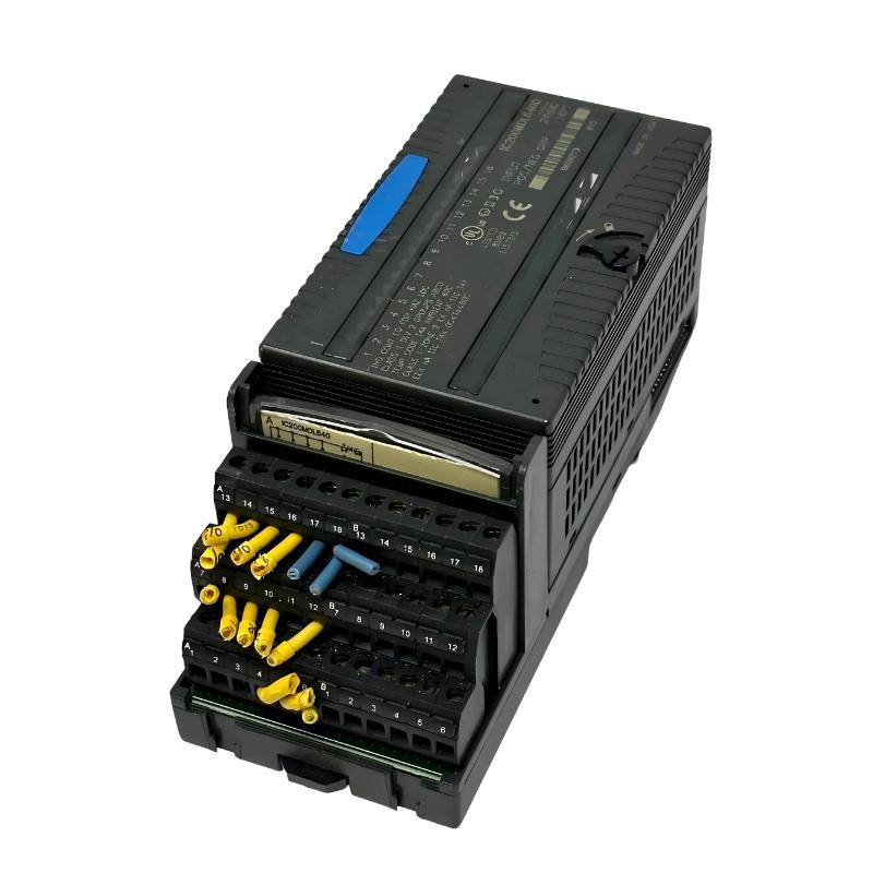
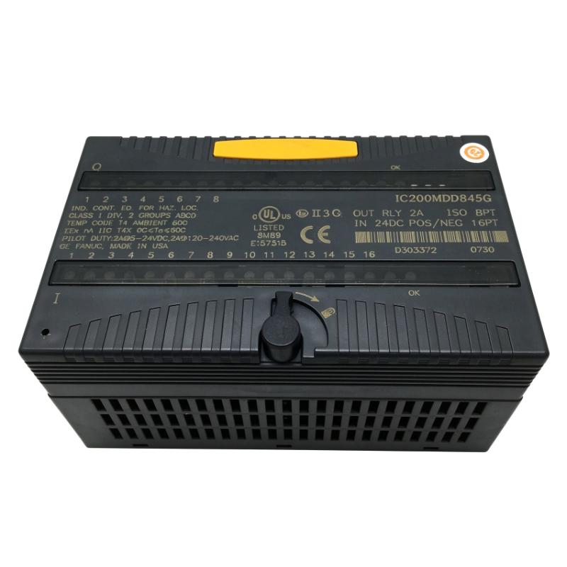
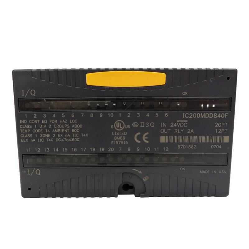
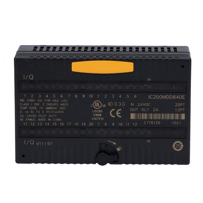
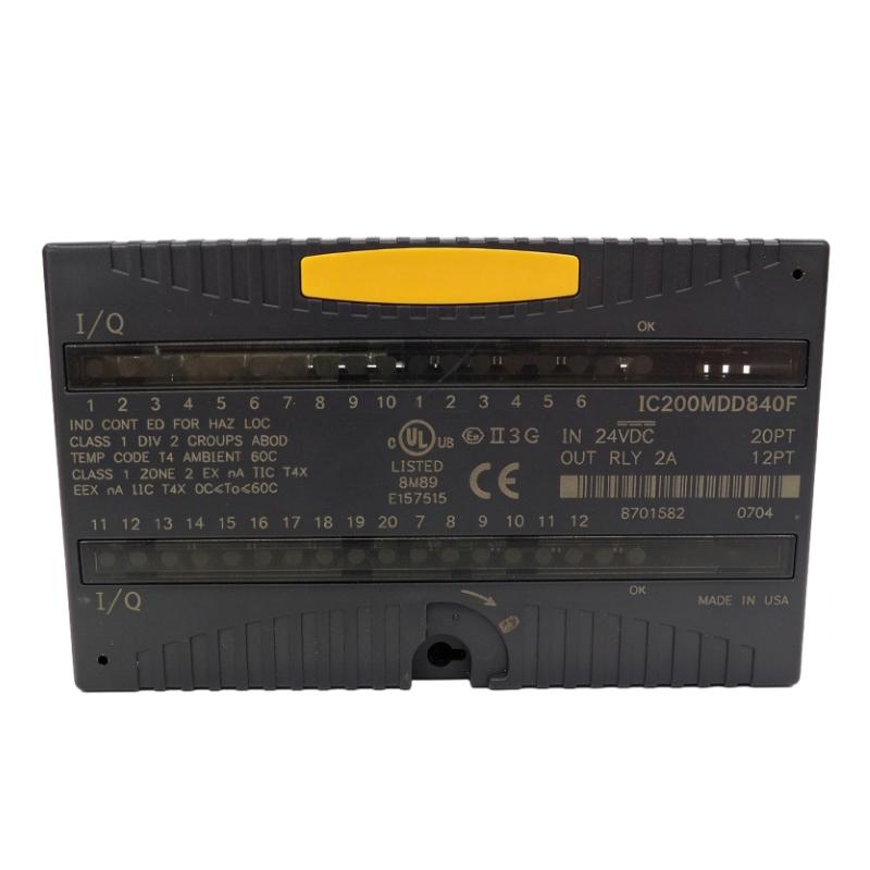
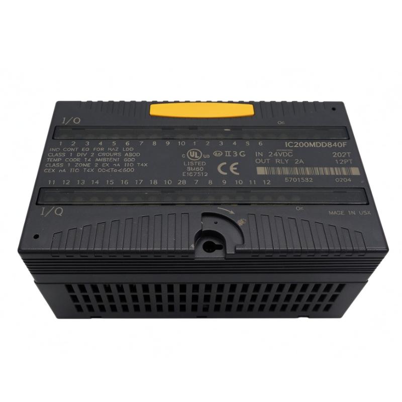
The GE IC200MDD840F VersaMax Discrete Hybrid I/O Module is a combination digital input and relay output module designed for GE Fanuc VersaMax automation systems. It allows a PLC or network interface unit to receive discrete signals from field devices and control external equipment through relay contacts.
Combining input and output functions in one module helps reduce the number of separate I/O modules required in suitable control-panel designs. It can interface with devices such as push buttons, limit switches, proximity sensors, contactors, indicator lamps, and other discrete-control equipment.
The base model IC200MDD840 provides 20 positive-logic 24 V DC inputs and 12 relay outputs, giving a total of 32 I/O points. The input channels are arranged in two groups of ten, while the relay outputs are divided into two groups of six. Each output group can handle a maximum current of 8 A, subject to the individual output and load ratings.
The module is part of the VersaMax distributed I/O family. It communicates with the system controller through the appropriate carrier base and backplane arrangement. The module receives operating power from the backplane, while external power supplies are required for the connected output loads.
The IC200MDD840F designation should be checked against the module’s complete nameplate and hardware revision before replacement. The suffix may identify a particular product revision or configuration, so it is important not to assume that every IC200MDD840 variant is interchangeable without verification.
Technical Specifications
| Parameter | Specification |
|---|---|
| Brand | GE Fanuc |
| Manufacturer | GE Intelligent Platforms / Emerson |
| Model | IC200MDD840F |
| Product Series | VersaMax |
| Product Type | Discrete Mixed I/O Module |
| I/O Configuration | 20 Inputs / 12 Relay Outputs |
| Total I/O Points | 32 |
| Input Type | Positive Logic / Sourcing |
| Nominal Input Voltage | 24 V DC |
| Input Voltage Range | 0–30 V DC |
| Input Channels | 20 |
| Output Type | Relay Contact |
| Relay Output Channels | 12 |
| Output Arrangement | Two groups of six |
| Maximum Current per Output Group | 8 A |
| Maximum Resistive Load | 2 A per point under specified voltage conditions |
| Output Load Supply | External power supply required |
| Backplane Current Consumption | 375 mA maximum at 5 V DC |
| Input Impedance | 10 kΩ maximum |
| Status Indicators | Individual point LEDs and module OK LED |
| Mounting / Connection | VersaMax carrier base |
| Dimensions Provided | 110 × 66.8 × 50 mm |
| Weight Provided | 0.16 kg |
Note: The listed dimensions correspond to the base module dimensions and do not include the carrier height or mating connectors. Verify the actual hardware revision and physical weight before procurement.
Function and Working Principle
The IC200MDD840F combines two essential PLC functions: receiving discrete input signals and switching external loads through relay outputs.
1. Discrete Input Signal Acquisition
The input section receives on/off signals from external field devices. Typical devices include:
- Push buttons and selector switches
- Limit switches
- Proximity sensors
- Photoelectric sensors
- Auxiliary contacts from contactors
- Machine status switches
The base IC200MDD840 configuration provides 20 positive-logic inputs designed for nominal 24 V DC signals. When an input signal reaches the required ON-state level, the corresponding input status is communicated to the PLC or network interface unit.
The input channels are arranged in two groups of ten. This grouping should be considered when designing field wiring and common connections.
2. Relay Output Control
The output section provides 12 relay channels. These outputs allow the control system to switch compatible external electrical loads.
Typical controlled devices include:
- Interposing relays
- Contactors
- Indicator lamps
- Solenoid valves
- Small control circuits
- Alarm and signaling devices
The relay contacts can switch specified AC and DC loads. The permitted current depends on the voltage and load type. Inductive loads may require additional suppression to protect contacts and reduce electrical interference.
3. PLC Data Exchange
The module exchanges discrete I/O data with the system controller through the VersaMax carrier and backplane arrangement.
Input states are transferred to the controller for logic processing. The controller then updates output data, allowing the relay channels to respond to programmed operating conditions.
This arrangement supports coordinated machine operation without requiring a separate input and output module for every signal group.
4. Status Indication
Individual point LEDs provide visual information about input and output logic states. An OK indicator provides information about the module’s backplane power status.
These indicators can help maintenance technicians identify wiring problems, missing signals, or module power issues during troubleshooting. However, an output status LED does not necessarily confirm that the connected external load is operating correctly.
Role in Industrial Control Systems
The IC200MDD840F acts as an interface between field devices and the VersaMax control system.
PLC Input Processing
The input channels allow a PLC to monitor machine conditions. For example, a limit switch can indicate that a mechanical assembly has reached a defined position. The controller can use this information to determine whether the next process step is permitted.
Output Device Control
The relay outputs allow the PLC to control external devices according to its program. A controller may energize a relay output when a machine condition is satisfied, activate an indicator lamp, or operate a compatible contactor control circuit.
Combined I/O in One Module
Because the module combines 20 inputs and 12 relay outputs, it can be useful in applications where both signal acquisition and discrete switching are needed in the same control area.
This arrangement can simplify I/O allocation and reduce the need for separate modules, provided that the input and output grouping meets the application’s wiring requirements.
Industrial Applications
1. Manufacturing Equipment
The module can receive signals from machine sensors and switches while controlling external relay-operated devices. It may be used in assembly machines, production equipment, and automated workstations.
2. Conveyor Systems
Input channels can monitor conveyor limit switches, sensor signals, and equipment status. Relay outputs can control compatible contactor circuits, signaling devices, or auxiliary equipment.
3. Packaging Machinery
Packaging systems often require a combination of product detection, position confirmation, and discrete device control. The mixed I/O configuration can support these functions as part of a larger PLC program.
4. Pump and Auxiliary Equipment
The module can monitor discrete equipment states and control compatible auxiliary relay circuits. Motor power switching should use appropriately rated contactors or motor starters rather than treating the module’s relay contacts as direct motor-drive outputs.
5. Process Automation
In process-control installations, the module can collect switch and equipment-status signals while controlling alarms, interposing relays, and other discrete devices. It is suitable for applications where the control logic is handled by a compatible VersaMax controller or network interface unit.
Installation and System Integration
1. Verify the Carrier Base
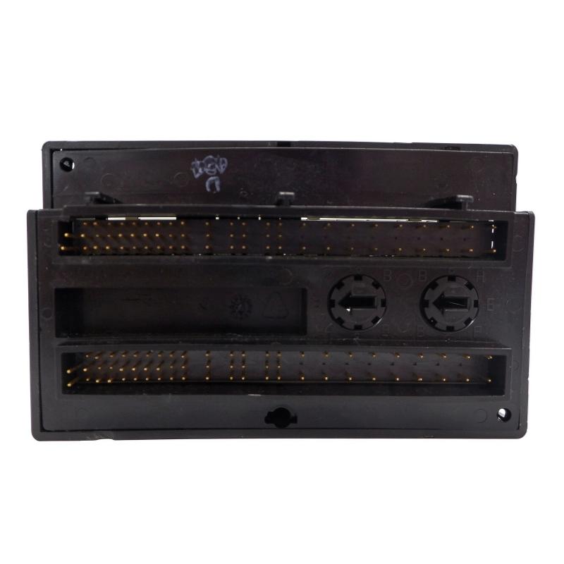
The IC200MDD840 family requires a compatible VersaMax carrier base. Confirm the carrier model and installation arrangement before mounting the module.
2. Check Input Wiring
The input section uses nominal 24 V DC positive-logic signals. Verify the field-device supply voltage, common connections, polarity, and input grouping before energizing the system.
3. Connect Relay Outputs Correctly
The 12 relay outputs are arranged in two groups of six. External power must be provided for the output loads. Check the voltage and current ratings for each connected load and for each output group.
Do not exceed the specified contact ratings. For inductive loads such as coils and solenoids, evaluate the need for suitable suppression components.
4. Confirm Backplane Power
The module draws operating power from the VersaMax backplane. Confirm that the system power supply and carrier arrangement can support the module’s maximum current requirement.
5. Configure the Controller
Install and configure the module through the appropriate VersaMax programming and hardware-configuration environment. Confirm the I/O address assignment and ensure that the PLC program references the correct input and output points.
6. Commission the Module
After installation, verify each input signal and test each relay output under controlled conditions. Check the module OK indicator, point LEDs, external power supplies, and connected devices before returning the machine to normal operation.
Compatible System Components
| Component | Function | Integration Considerations |
|---|---|---|
| VersaMax PLC CPU | Executes control logic | Confirm controller and firmware compatibility |
| VersaMax Network Interface Unit | Connects distributed I/O to a control network | Verify network architecture and module support |
| IC200CHS Series Carrier Base | Provides module mounting and backplane connections | Select a compatible carrier |
| VersaMax Power Supply | Provides system power | Check total backplane power capacity |
| 24 V DC Power Supply | Supplies field input devices | Confirm current capacity and correct polarity |
| Proximity Sensors | Detect objects and positions | Verify 24 V DC signal compatibility |
| Limit Switches | Provide machine-position signals | Check contact arrangement and wiring |
| Interposing Relays | Switch external loads | Select suitable coil and contact ratings |
| Contactors | Control larger electrical loads | Use appropriately rated control circuits |
Alternative Models and Replacement Considerations
The IC200MDD840F should be replaced only after checking the complete catalog number and hardware revision.
| Related Model | Description | Replacement Consideration |
|---|---|---|
| IC200MDD840 | 20-input / 12-relay-output mixed I/O module | Closely related base model; verify revision and compatibility |
| IC200MDD842 | 16-input / 16-output mixed module with DC outputs | Different output technology and channel configuration |
| IC200MDD843 | Mixed discrete input and relay output module | Verify channel count and electrical ratings |
| IC200MDD844 | 16-input / 16-output mixed I/O module | Different I/O allocation and output configuration |
| IC200MDL650 | VersaMax discrete input module | Input-only alternative; separate output module required |
| IC200MDL940 | VersaMax discrete output module | Output-only alternative; input module required separately |
A replacement decision should consider input voltage, output type, channel count, current ratings, group arrangement, carrier compatibility, and controller configuration. A module with a similar appearance may not provide the same electrical functions.
Key Advantages
Combined Input and Output Functions
The 20-input and 12-relay-output arrangement provides both signal acquisition and switching functions in a single module.
Flexible Field Device Connection
The 24 V DC positive-logic inputs can interface with commonly used industrial switches and sensors.
Relay-Based Switching
The relay outputs support compatible AC and DC loads within their specified electrical ratings.
Visual Status Monitoring
Individual point LEDs and an OK indicator assist with system monitoring and troubleshooting.
VersaMax System Integration
The module is designed for use within the VersaMax distributed I/O architecture, allowing it to exchange I/O data with compatible controllers and network interface units.
Compact Module Format
The module combines 32 I/O points in a compact form factor, helping organize control-panel layouts where compatible carrier bases are used.
Technical FAQs
1. What is the GE IC200MDD840F?
It is a VersaMax discrete mixed I/O module that combines 20 digital inputs and 12 relay outputs.
2. What input voltage does the module use?
The input section is designed for nominal 24 V DC positive-logic signals, with a specified input range of 0–30 V DC.
3. How many output channels are available?
The module provides 12 relay output channels arranged in two groups of six.
4. Does the module require an external power supply?
The module receives its operating power from the VersaMax backplane. However, external power is required for the connected relay output loads.
5. Can the relay outputs control motors directly?
The relay outputs are intended for loads within their specified contact ratings. Larger motors should be controlled through appropriately rated contactors or motor starters.
6. What carrier base does it use?
It requires a compatible VersaMax carrier base from the IC200CHS family. Confirm the exact carrier and system configuration before installation.
7. How can the module be diagnosed?
Check the module OK indicator, individual point LEDs, field wiring, external output power, and controller I/O configuration. A logic-side output indication does not necessarily prove that the external load is energized.
8. Is IC200MDD840F interchangeable with IC200MDD840?
The two designations are closely related, but the complete hardware revision and system compatibility should be confirmed before replacement. Verify the module label and applicable product documentation.
9. What should be checked before purchasing?
Confirm the complete catalog number, hardware revision, physical condition, terminal condition, carrier compatibility, and functional test status. Also verify the actual unit weight and included accessories.
Procurement and Maintenance Recommendations
When purchasing the GE IC200MDD840F, verify the full model designation and revision shown on the module label. Confirm that the product provides the required 20-input and 12-relay-output configuration and that it is suitable for the existing VersaMax controller and carrier base.
For used or refurbished equipment, request clear photographs of the front label, terminal connections, and module housing. Check for damaged connectors, corrosion, contamination, or signs of overheating. Where the module is intended for a critical production system, request functional testing of the input and relay output channels.
During maintenance, inspect field wiring, terminal connections, external load supplies, and carrier contacts. Verify that relay loads remain within the rated electrical limits. Keep the control cabinet clean and maintain suitable environmental conditions.
Because the module combines input and output functions, replacement planning should include a review of the PLC I/O address mapping and program logic. Confirm that the replacement preserves the correct channel assignments and output behavior before restarting the production system.
Conclusion
The GE IC200MDD840F VersaMax Discrete Hybrid I/O Module provides 20 positive-logic 24 V DC inputs and 12 relay outputs in one compact module. It is designed to interface field sensors and switches with a compatible VersaMax control system while allowing the controller to operate external relay-controlled devices.
Its mixed I/O arrangement, visual status indicators, and VersaMax system integration make it useful for manufacturing machinery, conveyors, packaging equipment, and other industrial automation applications. Before installation or replacement, verify the complete model designation, carrier compatibility, field wiring, external load requirements, and actual product condition.