

ProductPRODUCT
Featured products
Contact Us
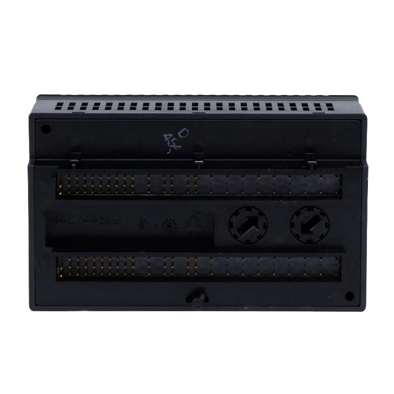
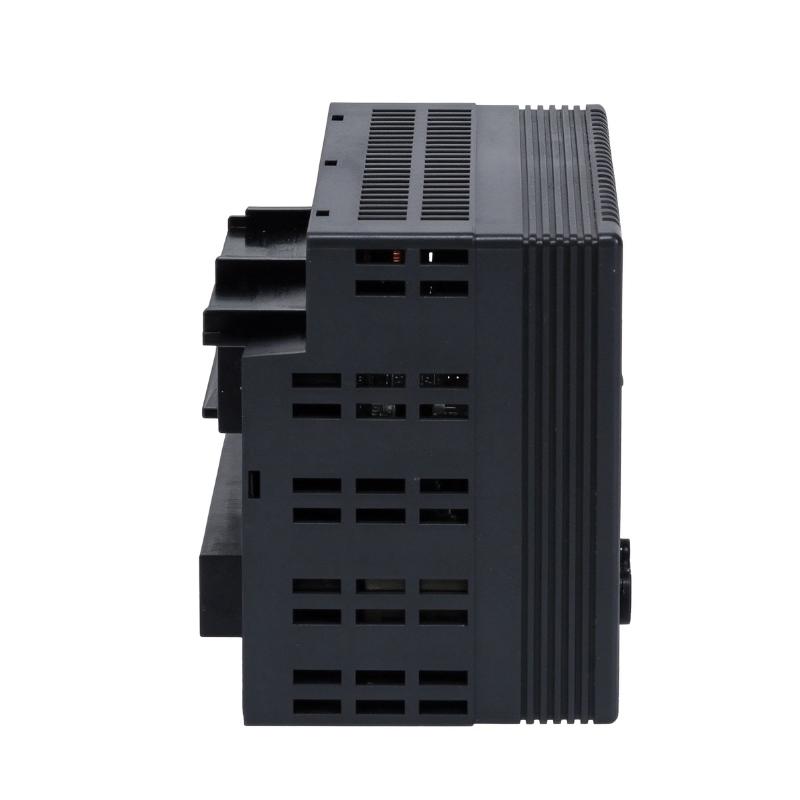
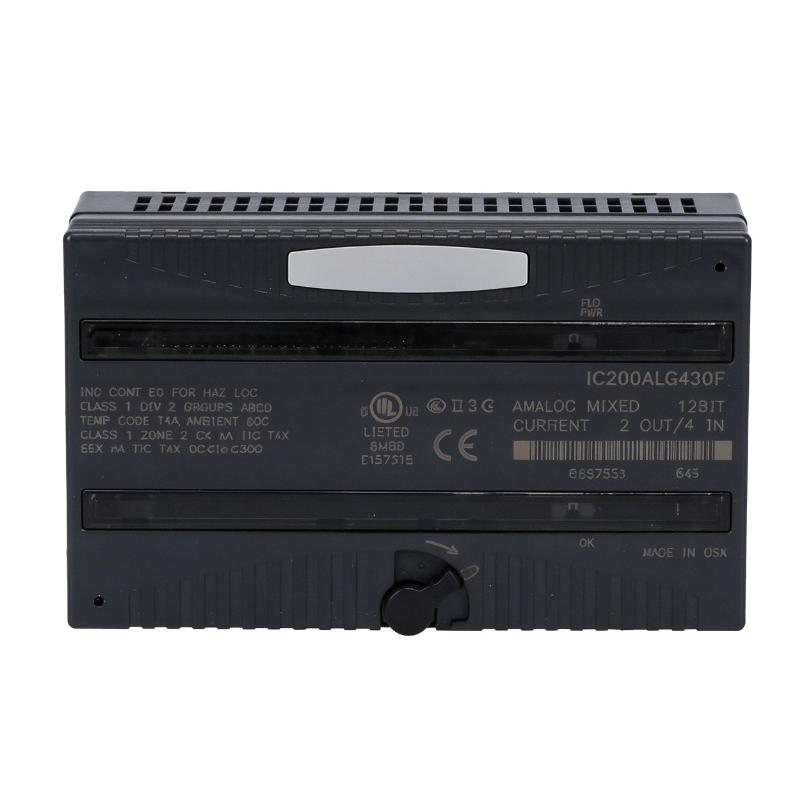
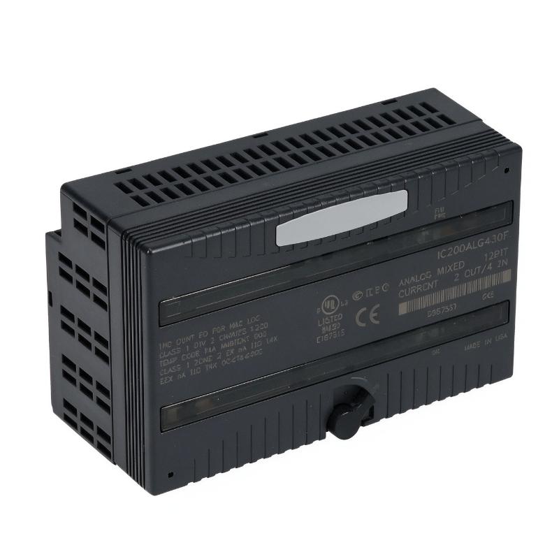
- GE
- IC200ALG430F
- VersaMax Analog Hybrid Module
- USA
- 110 x 66.8 x 50 mm
- 0.45 kg
- Xiamen, China
- New & In Stock
- T/T, PayPal, Western Union
- 1 Year
- 1-3 Working Days
- DHL, UPS, TNT, FedEx and EMS.
- 24-Hour Service
- COO
- 3
Our advantage

Global Logistics
We have a 10-year logistics and express cooperation agreement, so our products can be shipped to any place in the world.

Brand new and original
Our products are imported in bulk from the place of origin. Because of the cooperative relationship, our products are all original and 100% new.

24-hour service
We provide 7*24 hours service to our customers. We will be there whenever you need us.

Price advantage
All our products are priced very favorably because we have our own warehouse and supply.
| Company Information | |||
| [email protected] | |||
| Mobile | +8615980777398 | ||
| +8615980777398 | |||
| 15980777398 |
Product Overview
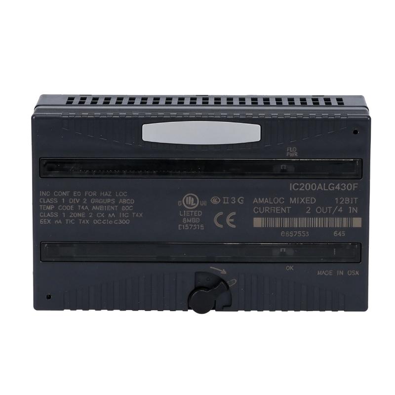
The GE IC200ALG430F VersaMax Analog Hybrid Module is an industrial programmable logic controller (PLC) I/O module designed to handle both analog current input and analog current output signals. It belongs to the GE Fanuc VersaMax automation platform, which is used in industrial control systems requiring flexible distributed I/O and process signal management.
Unlike a dedicated analog input or analog output module, the IC200ALG430F combines both functions in one compact module. It provides four differential analog current input channels and two single-ended analog current output channels. All six channels support 4–20 mA current signals, with 12-bit resolution for input and output conversion.
This combination allows a single module to receive measurements from field instruments and transmit control signals to external devices. For example, a PLC system can receive pressure, flow, or level measurements through the input channels and send corresponding control commands to compatible valves or other actuators through the output channels.
The module operates as part of a VersaMax I/O system. Intelligent processing is performed by the system CPU or Network Interface Unit (NIU), while the module exchanges input and output data through the backplane.
The IC200ALG430F is suitable for industrial applications where analog measurement and control signals need to be handled within the same I/O station. Its compact design also helps reduce the number of separate I/O modules required in installations with limited carrier capacity.
Technical Specifications
| Parameter | Specification |
|---|---|
| Brand | GE Fanuc / GE Intelligent Platforms |
| Manufacturer | General Electric |
| Model | IC200ALG430F |
| Product Series | VersaMax |
| Product Type | Analog Hybrid / Mixed I/O Module |
| Input Channels | 4 differential analog current inputs |
| Output Channels | 2 single-ended analog current outputs |
| Input Signal Range | 4–20 mA |
| Output Signal Range | 4–20 mA |
| Resolution | 12-bit |
| Input Filter Response | 5 ms |
| Input Update Rate | 0.4 ms |
| Output Update Rate | 0.3 ms maximum |
| Backplane Current Consumption | 50 mA at 5 V DC maximum |
| External Output Power Supply | +18 to +30 V DC |
| Input Isolation | 250 V AC continuous; 1500 V AC for 1 minute |
| Module Diagnostics | Loss of user-side power |
| LED Indicators | FLD PWR and OK |
| Mounting | VersaMax carrier base |
| Module Width | Single slot |
| Dimensions Provided | 110 × 66.8 × 50 mm |
| Weight Provided | 0.45 kg |
| Typical Application | Industrial analog signal acquisition and control |
Note: The supplied dimensions refer to the module body and do not include the carrier base or mating connectors. Verify the exact hardware revision and installation configuration before ordering.
Function and Working Principle
The IC200ALG430F performs two primary functions: converting incoming analog current signals into digital data for the PLC and converting digital control values from the PLC into analog current output signals.
1. Analog Current Input
The module provides four differential input channels for receiving 4–20 mA signals from field instruments.
Common field devices that use this signal range include:
- Pressure transmitters
- Flow transmitters
- Level transmitters
- Temperature transmitters with suitable signal converters
- Industrial process sensors
The input circuits receive the current signal and convert it into digital values. These values are transferred through the VersaMax backplane for processing by the CPU or NIU.
The differential input arrangement helps measure the signal between two input terminals and can support improved noise rejection when correctly wired.
2. Analog Current Output
The module also provides two single-ended analog current output channels. Each output can generate a 4–20 mA signal for compatible field devices.
Typical output applications include:
- Modulating control valves
- Current-controlled actuators
- Variable-speed drive reference inputs
- Process-control equipment
- Analog signal interfaces
The PLC calculates the required output value according to the control program and sends the corresponding digital data to the module. The module then converts that data into an analog current signal.
The output circuits require an external power supply. The recommended external supply range is +18 to +30 V DC, subject to the module’s installation requirements.
3. 12-Bit Signal Resolution
The IC200ALG430F uses 12-bit conversion for its analog input and output functions.
A 12-bit conversion provides 4096 possible digital levels. Across a configured 4–20 mA signal range, this allows the controller to represent changes in the measured or commanded current.
The practical measurement and control accuracy also depends on the module’s electrical characteristics, field wiring, signal quality, and connected instruments.
4. Signal Update and Filtering
The module provides an input update rate of approximately 0.4 ms and an output update rate of up to 0.3 ms. Its input filter response is approximately 5 ms.
These characteristics support analog signal processing in industrial control applications. Actual system response also depends on the PLC scan cycle, network or backplane performance, field-device response, and control-program execution.
5. Field Power Monitoring
The module includes FLD PWR and OK LED indicators.
The FLD PWR indicator shows the presence of user-side power for the field circuits. The OK indicator indicates that backplane power is available to the module.
The module can also report a loss-of-user-side-power fault. This diagnostic function helps maintenance personnel identify problems affecting the externally powered field-side circuits.
Role in Industrial Control Systems
The IC200ALG430F serves as an interface between analog field devices and a VersaMax PLC control system. It allows the controller to receive process measurements and transmit analog control commands.
PLC Signal Acquisition
The four input channels allow the PLC to receive current signals from multiple field instruments through one module.
For example, a process-control station may use separate channels to monitor pressure, flow, liquid level, and another process variable. The PLC receives the converted values and uses them in its control logic.
Analog Output Control
The two output channels allow the PLC to send analog commands to external equipment.
A control program may calculate a required valve position or motor reference value and transmit it through an output channel. The connected device responds according to its own input characteristics and configuration.
Distributed I/O Applications
The VersaMax platform supports distributed I/O architectures. The IC200ALG430F can be installed in a suitable I/O station and communicate with the controller through the VersaMax backplane and associated system hardware.
The CPU or NIU performs the intelligent processing, while the module provides the analog signal interface.
Process Monitoring and Control
By combining four input channels and two output channels, the module can support compact process-control loops.
For example, a PLC can monitor a pressure transmitter through an input channel, calculate a control response, and send a 4–20 mA command to a compatible control valve through an output channel.
This arrangement can reduce the need for separate input and output modules in suitable applications.
Industrial Applications
The IC200ALG430F can be used in industrial systems that require both analog measurement and analog control.
1. Water and Wastewater Treatment
Water treatment facilities use analog transmitters to monitor pressure, flow, and liquid level.
The module can receive 4–20 mA signals from compatible instruments and provide output signals for equipment such as modulating valves.
A PLC can use these signals to coordinate pumping, dosing, and water-level control processes.
2. Chemical Processing
Chemical production systems often require continuous monitoring of process variables.
The IC200ALG430F can receive analog signals from pressure and flow transmitters while providing output commands to compatible control devices.
Correct signal scaling and suitable electrical isolation are important when integrating the module into process-control installations.
3. Pumping and Fluid Control
Industrial pumping systems may use pressure and flow transmitters to provide feedback to a PLC.
The module can acquire these measurements and send analog commands to compatible control equipment. This allows the PLC to coordinate pump operation with other process devices.
4. Manufacturing and Production Lines
Manufacturing equipment may require analog feedback from sensors and analog commands to actuators.
The four input channels and two output channels provide a compact I/O solution for selected applications involving process measurement, machine regulation, and equipment coordination.
5. HVAC and Building Automation
Industrial HVAC systems may use analog sensors to monitor temperature, pressure, and flow.
The module can receive suitable 4–20 mA signals and transmit analog commands to compatible control devices. Its use depends on the signal requirements and the design of the VersaMax control system.
6. Energy and Utility Systems
Utility installations often require continuous measurement of process conditions and control of associated equipment.
The IC200ALG430F can be used where analog input acquisition and current-output control are required within a compatible VersaMax PLC architecture.
Installation and System Integration
Correct installation is essential for reliable signal conversion and stable operation.
1. Verify the Module Revision
Before installation, check the complete catalog number and hardware revision.
VersaMax documentation identifies revision requirements for certain analog modules used in expansion racks. The IC200ALG430 requires revision C or later for the listed expansion-rack compatibility condition.
The suffix F identifies a later catalog revision, but the complete system configuration should still be checked against the applicable VersaMax hardware documentation.
2. Install the Correct Carrier Base
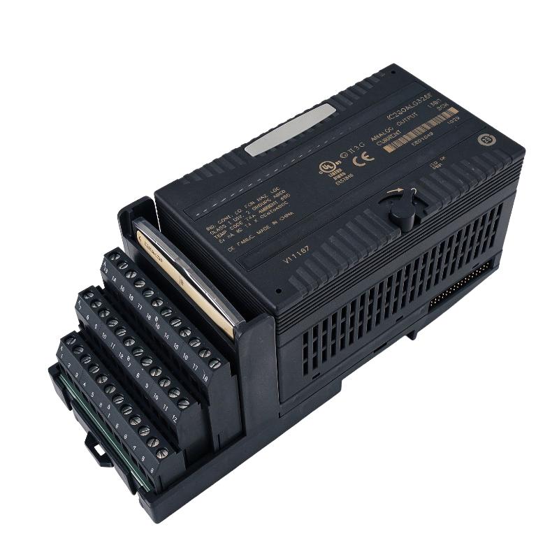
The IC200ALG430F is a single-slot module and requires a compatible VersaMax carrier base.
The carrier provides the physical mounting and electrical connections for the module. Confirm the carrier type, terminal arrangement, and available installation space before mounting.
The module dimensions of 110 × 66.8 × 50 mm do not include the carrier base or mating connectors.
3. Connect Analog Input Signals
The four input channels accept differential 4–20 mA current signals.
Use appropriate shielded twisted-pair cables for analog connections. Follow the field instrument’s wiring requirements and the module’s terminal configuration.
Cable shields should be grounded according to the installation design. Improper grounding or routing near high-current power conductors can introduce interference into analog measurements.
4. Connect Analog Output Circuits
The two output channels provide 4–20 mA current signals.
An external power supply is required for the output circuits. The recommended supply range is +18 to +30 V DC, including ripple, according to the module documentation.
Verify the output-loop wiring, connected device input impedance, and external supply capacity before commissioning.
5. Configure the PLC
The CPU or NIU performs the intelligent processing for the module.
The system configuration must allocate the correct input and output data areas. The module provides four words of analog input data and receives two words of analog output data.
The PLC program should apply the appropriate scaling, engineering-unit conversion, alarm limits, and output-control logic.
6. Configure Output Default Behavior
The module supports output behavior selection through a jumper arrangement on the carrier.
Depending on the configuration, outputs can hold their last commanded states or default to 4 mA if backplane power or communications are interrupted or the PLC stops.
The external field-side power supply must remain available for the configured output behavior to operate as intended. Verify the selected mode against the machine’s process-safety requirements.
7. Commission and Test
After installation, check the module’s physical seating, wiring, external power supply, and LED indicators.
Test each input channel with a suitable current source and confirm that the PLC displays the expected value. Test each output channel with an appropriate measuring instrument or connected field device.
Record the final configuration and verify that fault diagnostics and output default behavior meet the application requirements.
Compatible System Components
The IC200ALG430F operates within the GE Fanuc VersaMax automation platform. Its installation and operation depend on compatible carriers, controllers, power supplies, and field devices.
| Component | Function | Integration Considerations |
|---|---|---|
| VersaMax CPU | Executes the PLC control program | Confirm system configuration and I/O mapping |
| VersaMax NIU | Provides network interface functions for distributed I/O | Verify compatibility with the controller and network architecture |
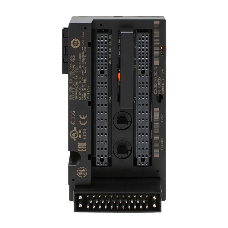
| IC200CHS Series Carrier | Provides module mounting and terminal connections | Select a compatible carrier base |
| VersaMax Power Supply | Supplies power to the I/O station | Confirm available power capacity |
| 4–20 mA Transmitters | Provide process measurements | Check signal range and differential wiring |
| Modulating Control Valves | Receive analog control commands | Verify current-input compatibility |
| External 24 V DC Supply | Powers the output field circuits | Follow the recommended external supply range |
| Shielded Twisted-Pair Cable | Carries analog signals | Apply suitable shielding and grounding |
| Industrial Ethernet or Field Network Equipment | Connects distributed control stations | Network integration depends on the selected CPU or NIU |
The listed components are examples of equipment used in a complete VersaMax control installation. They are not necessarily supplied with the IC200ALG430F module.
Alternative Models and Replacement Considerations
Several VersaMax analog modules provide related functions, but their signal types and channel configurations differ.
| Model | Function | Main Difference |
|---|---|---|
| IC200ALG430 | Analog mixed current module | Four 4–20 mA inputs and two 4–20 mA outputs |
| IC200ALG431 | Analog mixed voltage module | Four 0–10 V DC inputs and two 0–10 V DC outputs |
| IC200ALG432 | Analog mixed bipolar voltage module | Four ±10 V DC inputs and two ±10 V DC outputs |
| IC200ALG320 | Analog voltage output module | Dedicated voltage output functionality |
| IC200ALG321 | Analog current output module | Dedicated current output functionality |
| IC200ALG230 | Analog voltage input module | Dedicated voltage input functionality |
These models should not be treated as direct substitutes without checking the complete application requirements.
Before replacing an IC200ALG430F, verify:
- Number of analog input and output channels.
- Current or voltage signal requirements.
- Input and output resolution.
- Carrier and terminal compatibility.
- Hardware revision requirements.
- External output power supply.
- PLC or NIU compatibility.
- Input and output data mapping.
- Output default behavior.
- Field wiring and grounding arrangements.
A replacement with a different signal type may require wiring changes, PLC program modifications, or changes to connected field instruments.
Key Advantages
Combined Analog Input and Output
The module combines four analog current inputs and two analog current outputs in one unit, providing both measurement and control capabilities.
4–20 mA Signal Support
Its current input and output channels support a widely used industrial analog signal standard.
12-Bit Resolution
The 12-bit conversion capability provides digital representation of incoming measurements and outgoing control values.
Compact Single-Slot Design
The module occupies one VersaMax I/O slot, helping reduce the number of separate modules required in suitable installations.
Field Power Diagnostics
The FLD PWR and OK indicators provide useful information about field-side and backplane power conditions.
Configurable Output Defaults
The output default arrangement supports hold-last-state or 4 mA default behavior under specified power or communication interruption conditions.
Integration with VersaMax Systems
The module is designed for use within compatible VersaMax I/O architectures, supporting PLC-based process monitoring and control.
Technical FAQs
1. What is the GE IC200ALG430F?
The IC200ALG430F is a GE Fanuc VersaMax analog mixed I/O module. It combines four differential 4–20 mA analog inputs and two single-ended 4–20 mA analog outputs.
2. How many input channels does the module have?
It has four differential analog current input channels.
3. How many output channels does it provide?
It provides two single-ended analog current output channels.
4. What signal range does it support?
Both input and output channels support 4–20 mA current signals.
5. What is the module’s resolution?
The input and output conversion circuits use 12-bit resolution.
6. Does the module require an external power supply?
Yes. The output circuits require an external power supply. The recommended range is +18 to +30 V DC, including ripple, according to the module documentation.
7. Can it be used with a VersaMax PLC?
Yes. It is designed for the GE Fanuc VersaMax I/O platform and exchanges data with the CPU or Network Interface Unit through the system backplane.
8. What do the LED indicators mean?
The FLD PWR LED indicates the presence of user-side field power, while the OK LED indicates the presence of backplane power.
9. What happens if field-side power is lost?
The module can report a loss-of-user-side-power fault. The field-side power condition should be checked before assuming that the module itself has failed.
10. Can IC200ALG431 replace IC200ALG430F?
Not as a direct substitute in an existing 4–20 mA installation. IC200ALG431 is designed for 0–10 V DC analog signals, while IC200ALG430F uses 4–20 mA current signals. Signal compatibility must be verified before replacement.
Procurement and Maintenance Recommendations
When purchasing the GE IC200ALG430F, verify the complete catalog number, hardware revision, physical condition, and compatibility with the existing VersaMax carrier and controller.
Because analog modules directly interface with field instruments, it is important to confirm that the replacement has the correct number of input and output channels and supports the required 4–20 mA signal range.
For used or refurbished equipment, inspect the terminal connections, module housing, printed circuit board condition where accessible, and LED operation. Request functional test information when the module is intended for a critical process-control application.
During routine maintenance, check the external output power supply, analog wiring, cable shielding, grounding, and field instrument connections. Unexpected signal readings may be caused by wiring faults, incorrect loop power, grounding problems, or field-device issues rather than an internal module failure.
Keep a record of the PLC I/O configuration, signal scaling, output default selection, and module revision. This information can simplify troubleshooting and reduce commissioning time when a replacement is installed.
Conclusion
The GE IC200ALG430F VersaMax Analog Hybrid Module is a mixed analog I/O component designed for industrial control systems that require both current-signal acquisition and analog output control. It provides four differential 4–20 mA inputs and two single-ended 4–20 mA outputs, with 12-bit resolution for both functions.
Its single-slot design, field power diagnostics, and configurable output behavior make it a useful component in compatible VersaMax PLC installations. Before purchasing or replacing the module, engineers should verify the catalog number, hardware revision, carrier compatibility, external output power requirements, and PLC configuration to ensure reliable integration.