
NewsNEWCENTER
Featured products


Contact Us
GE HE700GEN200 uGENI VME Interface Module Troubleshooting and Fault Diagnosis Guide
2026-11-02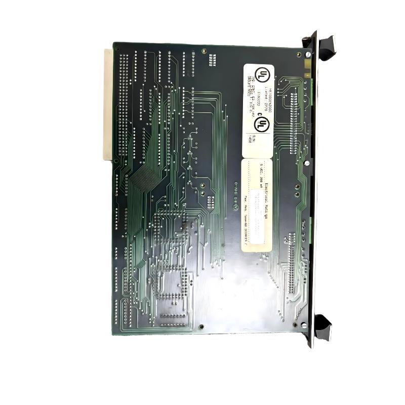
1. Introduction
The **GE HE700GEN200 uGENI VME Interface Module** is a dual-channel Genius communication interface designed for VME-based industrial control systems. It provides two independent Genius bus interfaces, allowing a VME host computer to exchange data with distributed Genius I/O devices. The module is commonly associated with legacy GE Fanuc control architectures and Horner APG uGENI VME interface technology. It can be used in applications where a VME host needs to communicate with remote I/O stations through the Genius network. When the HE700GEN200 develops a fault, symptoms may include communication loss, failure to initialize, inaccessible VME memory, intermittent device data, or problems affecting only one of the two Genius channels. However, these symptoms do not necessarily indicate an internal module failure. Incorrect DIP switch settings, VME address conflicts, network wiring problems, duplicate Genius addresses, incorrect baud rates, and termination faults can produce similar results. This guide provides a structured approach to identifying and troubleshooting common HE700GEN200 problems.
2. Product Identification and Troubleshooting Fundamentals
Before starting troubleshooting, confirm the module identity and understand its main interfaces.
| Parameter | Description |
|---|---|
| Model | HE700GEN200 |
| Product Family | Horner APG uGENI VME Interface |
| Compatible Control Technology | GE Fanuc Genius communication architecture |
| Module Type | Dual-channel Genius interface |
| Backplane | VME |
| Communication Channels | Two independent Genius interfaces |
| Network Configuration | DIP switch configuration |
| Network Topology | Genius serial bus |
| Typical Application | VME-based industrial control and distributed I/O |
The HE700GEN200 is the dual-channel version of the uGENI VME interface family. The HE700GEN100 is the corresponding single-channel version. These models should not be treated as interchangeable when the application requires two independent Genius networks. The module uses several configuration DIP switches. In particular, Switch 2 configures the first uGENI channel, while Switch 3 configures the second channel. Other switches are associated with VME addressing, interrupts, and interface operation.
3. Common HE700GEN200 Fault Symptoms
3.1 VME Host Cannot Access the Module
One common problem is that the VME host cannot communicate with the HE700GEN200 after installation or system startup. Possible causes include: – Incorrect VME address configuration. – Unsupported VME address modifier codes. – USER or SUPERVISOR access-mode mismatch. – Incorrect DIP switch settings. – Poor module seating in the backplane. – Incorrect host application memory mapping. – VME backplane or host CPU problems. Recommended checks: 1. Confirm that the module is fully inserted into the correct VME slot. 2. Inspect the backplane connector for contamination or mechanical damage. 3. Review the VME address settings. 4. Confirm that the host CPU supports the selected address modifier codes. 5. Check whether the application uses the correct address space. 6. Review the host system’s startup and diagnostic information. The module and host CPU must use compatible VME addressing arrangements. A physically installed board may still remain inaccessible if the address configuration is incorrect.
3.2 Genius Communication Failure
The VME host may recognize the module, but one or both Genius networks may fail to communicate with their connected devices. Possible causes include: – Incorrect Genius bus address. – Incorrect baud-rate selection. – Duplicate device addresses. – Incorrect network wiring. – Missing or incorrect termination. – Damaged communication cable. – A field device that is powered off or malfunctioning. – A short circuit on the Genius bus. Recommended checks: 1. Identify which Genius channel is affected. 2. Check the corresponding DIP switch configuration. 3. Confirm the baud rate used by the network devices. 4. Verify that all devices have unique addresses. 5. Inspect the Serial 1 and Serial 2 connections. 6. Check the network termination at both physical ends. 7. Review the module and host communication status. Do not change both channel configurations simultaneously. Troubleshoot each network independently to make it easier to identify the source of the fault.
3.3 Only One Genius Channel Is Working
The HE700GEN200 contains two independent Genius interfaces. A problem affecting only one channel may be caused by that channel’s configuration or external network. For example, the first channel may communicate normally while the second channel reports missing devices or communication errors. Possible causes include: – Incorrect settings on Switch 3. – Incorrect baud rate on the second Genius network. – Duplicate device addresses on that network. – Damaged second-channel wiring. – Incorrect termination. – A fault in the associated remote I/O device. Recommended checks: – Compare the two channel configurations. – Confirm that Switch 2 and Switch 3 contain the intended settings for their respective channels. – Inspect the second channel’s cable and terminal connections. – Check the address allocation of all connected devices. – Verify the second network’s baud rate. – Review channel-specific diagnostic information. Do not assume that the second channel is defective simply because the first channel operates normally.
3.4 Communication Is Intermittent
Intermittent communication may appear as devices repeatedly disappearing and returning, unstable I/O data, or occasional communication errors. Potential causes include: – Loose network terminals. – Damaged or poorly shielded cables. – Incorrect bus termination. – Electrical interference. – Unstable power to remote devices. – Cable routing too close to high-power equipment. – An inconsistent baud-rate configuration. Recommended checks: 1. Inspect the complete Genius cable route. 2. Check terminal tightness and cable condition. 3. Verify shield connections against the network design. 4. Confirm the terminating resistors are installed correctly. 5. Check the power supply condition of affected remote devices. 6. Compare communication events with machine operating conditions. If communication failures occur when large motors, drives, or switching equipment operate, investigate possible electrical interference and grounding problems.
3.5 Module Fails to Initialize
The uGENI interfaces require initialization by the VME host application. If initialization is incomplete, communication may not become available even when the board is physically installed correctly. Possible causes include: – Incorrect VME memory or I/O addressing. – Incorrect initialization sequence. – Invalid interrupt configuration. – Incorrect reset control. – A conflict on the Genius network. – A problem with the module or VME host. The uGENI initialization process uses the appropriate Short Address I/O space. The host application controls the reset and initialization sequence. If interrupts are used, the required interrupt vector must be configured before the interface is brought out of reset. Recommended checks: – Review the host application’s initialization sequence. – Confirm the configured VME address space. – Check the interface status information. – Verify the Genius network for address conflicts. – Confirm interrupt configuration where applicable. – Compare the current settings with the approved system configuration. Do not repeatedly reset the module without recording its status and identifying the cause of the initialization failure.
3.6 Interrupt Communication Problems
Some applications use VME interrupts to coordinate communication between the HE700GEN200 and the host CPU. If interrupt events are not received correctly, the problem may be related to interrupt priority, masking, vector configuration, or VME interrupt-chain placement. Recommended checks: – Confirm whether the application actually uses VME interrupts. – Verify the configured interrupt priority. – Check the interrupt mask and USER mode settings. – Confirm that the interrupt vector matches the host software configuration. – Verify that the module is installed in a suitable position in the VME interrupt chain. If the application does not use interrupts, do not introduce interrupt configuration changes as an attempted repair.
4. Understanding the DIP Switch Configuration
The DIP switches are an important part of HE700GEN200 troubleshooting. Incorrect settings can prevent communication even when the board and external wiring are in good condition. The module’s configuration includes several switch groups.
| DIP Switch | Configuration Function |
|---|---|
| Switch 1 | Interrupt priority |
| Switch 2 | Genius configuration for uGENI 1 |
| Switch 3 | Genius configuration for uGENI 2 |
| Switch 4 | Interrupt mask and USER mode configuration |
| Switch 5 | uGENI memory address configuration |
| Switch 6 | uGENI I/O address and interrupt vector configuration |
4.1 Check the Genius Bus Address
The Genius bus address configuration for each channel is independent. Switch 2 controls uGENI 1, and Switch 3 controls uGENI 2. The address is configured using the designated address switches. Confirm the selected address against the network’s device list. A duplicate address can prevent correct communication or cause abnormal network behavior.
4.2 Check the Baud Rate
The HE700GEN200 supports the following Genius baud-rate settings:
| Baud Rate | Switch 7 | Switch 6 |
|---|---|---|
| 153.6K Extended | ON | ON |
| 38.4K | ON | OFF |
| 76.8K | OFF | ON |
| 153.6K Standard | OFF | OFF |
These settings apply to the Genius configuration switch for each channel. Confirm the selected rate against the connected Genius devices and existing network configuration.
4.3 Record Switch Positions Before Adjustment
Before changing any DIP switch: 1. Photograph the existing settings. 2. Record the original positions. 3. Identify the affected channel. 4. Compare the settings with the approved configuration. 5. Change only the settings required by the documented correction. 6. Repeat the required initialization and communication tests. Never change switch positions randomly. Incorrect VME address, interrupt, or Genius settings can introduce additional problems.
5. Step-by-Step Troubleshooting Procedure
Step 1: Collect System Information
Record the following information before beginning hardware work: – Complete module model number. – VME rack and slot position. – Host CPU model. – Current DIP switch settings. – Genius channel affected. – Network baud rate. – Device addresses. – Exact error messages. – Whether the problem appeared after installation, maintenance, or a configuration change. This information helps distinguish a VME access problem from a Genius network communication fault.
Step 2: Determine Whether the Fault Is on the VME Side or Genius Side
First determine whether the host can access the module. If the host cannot access the configured address space, investigate VME addressing, backplane connections, host CPU compatibility, and module seating. If the host can access the module but Genius devices are unavailable, focus on the relevant Genius channel, DIP switch configuration, network wiring, and device addresses. This separation prevents unnecessary replacement of a functioning interface module.
Step 3: Inspect Network Wiring
Check the Genius bus connections, including Serial 1, Serial 2, Shield In, and Shield Out. Verify the cable routing and terminal connections against the approved wiring diagram. Inspect for damaged insulation, loose conductors, corrosion, and incorrect shield connections. Do not disconnect or reconnect live network wiring unless the approved maintenance procedure specifically permits it.
Step 4: Verify Termination
Genius network termination is essential for stable serial communication. The bus should be terminated at its two physical ends. The terminating resistor should match the characteristic impedance of the cable. Where the cable impedance is unknown, the applicable uGENI installation instructions specify the use of 120-ohm termination resistors. Check that termination has not been installed at intermediate devices and that both physical ends are correctly terminated.
Step 5: Verify Device Addresses and Baud Rates
Prepare a complete list of connected Genius devices and their assigned addresses. Confirm that: – Each device has a unique address. – The controller address matches the network design. – The first and second channels use their intended configurations. – The baud rate is consistent across each network. – No device has been accidentally assigned an address already in use.
Step 6: Inspect the VME Module
If the network checks do not resolve the problem, arrange an approved shutdown and isolate the relevant equipment before inspecting the module. Check for: – Bent or damaged backplane connector pins. – Contamination or corrosion. – Damaged PCB components. – Cracked solder joints. – Loose mounting hardware. – Signs of overheating. – Physical damage to front-panel connectors. Use ESD protection throughout the inspection.
Step 7: Perform Controlled Reinitialization
After confirming the hardware and configuration, perform the approved initialization sequence through the host application. If interrupts are used, confirm the vector configuration before releasing the uGENI interfaces from reset. Observe the interface status information and check whether communication becomes available. Record the results before performing additional changes.
6. Troubleshooting Reference Table
| Fault Symptom | Possible Cause | Recommended Action |
|---|---|---|
| VME host cannot access module | Incorrect address configuration or backplane connection | Verify VME address settings, address modifiers, and module seating. |
| Both Genius channels fail | Initialization, shared VME access, or module-level problem | Check host initialization and VME communication first. |
| Only one Genius channel fails | Incorrect channel DIP switch settings or network fault | Inspect the affected channel’s address, baud rate, and wiring. |
| Devices repeatedly disappear | Termination, cable, shielding, or electrical interference | Inspect the complete bus and verify termination. |
| Duplicate address indication or conflict | Two devices assigned the same bus address | Review and correct the Genius address allocation. |
| Interface does not initialize | Incorrect reset sequence or address configuration | Review the host initialization procedure and status information. |
| Interrupts not received | Incorrect interrupt level, vector, mask, or chain position | Verify the complete VME interrupt configuration. |
| Communication fails after maintenance | Changed DIP switch or wiring configuration | Compare the current installation with the recorded original settings. |
7. When Should the HE700GEN200 Be Replaced?
Replacing the module should be considered only after external communication and configuration problems have been investigated. Possible reasons for replacement include: – Confirmed internal hardware failure. – Physical damage to the PCB or connectors. – Persistent interface faults after VME addressing and initialization have been verified. – A Genius channel that remains inoperative after its external network has been checked. – Repeated module-level failures confirmed through qualified testing. Before ordering a replacement, verify the complete HE700GEN200 model number and the system’s dual-channel requirement. The HE700GEN100 is a single-channel interface and is not an equivalent replacement where both Genius networks are required.
8. Replacement and Post-Repair Verification
After replacing the module, complete the following checks.
Hardware Installation
Verify that the replacement is correctly seated in the VME rack and that its connectors and retaining hardware are secure.
DIP Switch Configuration
Restore the approved configuration for VME addressing, interrupt operation, and both Genius channels. Compare each switch group with the recorded system settings.
VME Access Test
Confirm that the host CPU can access the module using the configured address space and access mode.
Genius Channel Testing
Test the first and second Genius networks independently. Confirm that the expected devices are recognized and that data exchange is stable.
Application Verification
Check the host application’s I/O data and diagnostics. Verify representative remote I/O points under approved operating conditions.
Operational Monitoring
Monitor the module for repeated communication errors, initialization failures, and device dropouts before returning the affected system to normal operation.
9. Preventive Maintenance Recommendations
The HE700GEN200 is a legacy interface module, so maintaining accurate configuration records is particularly important. Recommended practices include: 1. Record all DIP switch settings and VME address assignments. 2. Maintain an updated list of Genius device addresses. 3. Document the baud rate of each network. 4. Inspect network wiring and termination during scheduled maintenance. 5. Check the VME backplane and module connectors for contamination or damage. 6. Review communication diagnostics for recurring faults. 7. Store spare modules in suitable antistatic packaging. 8. Verify replacement compatibility before installation. 9. Keep the original application initialization procedure available. 10. Avoid unapproved changes to interrupt and address settings. Good documentation makes it easier to restore the original operating configuration after maintenance or replacement.
10. Frequently Asked Questions
What is the GE HE700GEN200 used for?
The HE700GEN200 is a dual-channel uGENI VME interface module. It allows a VME-based host system to communicate with two Genius distributed I/O networks.
Why does the HE700GEN200 have two Genius channels?
The dual-channel design allows one module to interface with two independent Genius networks. Each channel has its own network configuration and should be diagnosed separately.
What is the difference between HE700GEN100 and HE700GEN200?
The HE700GEN100 provides one Genius communication channel, while the HE700GEN200 provides two. A single-channel module should not be substituted where the application requires both networks.
What should I check if the VME host cannot recognize the module?
Check the VME address configuration, supported address modifier codes, USER or SUPERVISOR access mode, backplane connection, and host application initialization.
Why does only one Genius channel fail?
The affected channel may have an incorrect DIP switch setting, baud rate, device address, cable connection, or termination arrangement. Check the two networks independently.
Can an incorrect baud rate cause communication failure?
Yes. The HE700GEN200 supports 38.4K, 76.8K, and 153.6K Genius communication settings, including standard and extended 153.6K modes. The selected configuration must match the connected network devices.
Why are terminating resistors necessary?
Termination helps reduce signal reflections on the Genius bus. The network should be terminated at both physical ends using resistors appropriate for the cable impedance.
Does the HE700GEN200 require initialization after power-up?
Yes. The VME host application must initialize the uGENI interfaces using the appropriate addressing and reset procedure before normal communication begins.
Can I replace the HE700GEN200 with another VME communication module?
Not automatically. The replacement must support the required Genius protocol, dual-channel operation, VME interface, addressing arrangement, and application software.
11. Technical Summary
The GE HE700GEN200 uGENI VME Interface Module provides dual-channel Genius communication for compatible VME-based industrial control systems. Its troubleshooting process should begin by separating VME host-access problems from Genius network communication problems. The most important checks include VME address configuration, DIP switch settings, Genius bus addresses, baud rates, network wiring, termination, and host initialization. If both channels fail, investigate shared VME and initialization conditions first. If only one channel fails, focus on that channel’s configuration and external network. Accurate configuration records, careful inspection, and independent testing of both Genius channels can reduce unnecessary replacement and help maintain reliable operation of legacy industrial automation systems.