
NewsNEWCENTER
Featured products


Contact Us
GE HE700GEN200 uGENI VME Interface Module Installation and Commissioning Guide
2026-11-02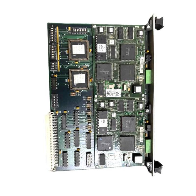
1. Product Overview
The **GE HE700GEN200 Interface Module** is a dual-channel Genius interface module designed for VME-based industrial control systems. It belongs to the uGENI VME Interface product family associated with Horner APG and GE Fanuc control technology. The module provides communication between a VME host system and GE Genius distributed I/O networks. It can operate as an interface to Genius field devices and can replace or operate alongside a conventional Genius Bus Controller (GBC), depending on the system architecture. The HE700GEN200 is designed for applications where an existing industrial control system needs to exchange data with remote I/O devices over the Genius bus. Its dual-channel design allows two Genius communication networks to be connected through one VME interface module. Unlike an ordinary analog or digital I/O module, the HE700GEN200 primarily performs communication and interface functions. Correct installation therefore requires attention to VME addressing, Genius bus configuration, network wiring, termination, and controller initialization.
2. Technical Specifications
| Parameter | Description |
|---|---|
| Manufacturer / Product Family | Horner APG / GE Fanuc-compatible |
| Model | HE700GEN200 |
| Product Type | uGENI VME Interface Module |
| Interface Function | Dual-channel Genius bus communication |
| Backplane Interface | VME |
| Module Format | Single-slot VME module |
| Genius Channels | 2 |
| Network Topology | Daisy-chain bus |
| Maximum Devices | Up to 32 devices on a Genius bus |
| Network Terminals | Serial 1, Serial 2, Shield In, Shield Out |
| Configuration | VME address configuration and Genius bus configuration |
| Installation Platform | Compatible VME rack and host system |
The exact electrical requirements, address settings, interrupt configuration, and supported communication rates must be checked against the applicable HE700GEN200 hardware revision and system documentation.
3. Main Functions and Operating Principles
3.1 Dual-Channel Genius Communication
The HE700GEN200 provides two Genius communication channels. Each channel can connect to a separate Genius network, allowing the VME host to exchange information with distributed field devices through the module. Each Genius network can support up to 32 devices, subject to the network configuration and device limitations.
3.2 VME Backplane Interface
The module occupies a single VME slot and communicates with the host CPU through the VME backplane. The host accesses the module using the configured VME address space. Correct address mapping is essential. The VME CPU and the uGENI module must use compatible address modes and address ranges.
3.3 Genius Bus Controller Integration
The HE700GEN200 can replace a conventional Genius Bus Controller in suitable configurations or operate alongside an existing controller. The actual arrangement depends on the application and network design. When multiple controllers are present, Genius bus addresses and controller roles must be assigned correctly to avoid address conflicts.
3.4 Network Data Exchange
The module handles communication between the VME host and Genius network devices. The host uses the module’s memory and I/O data structures to exchange information with connected devices. The host application must initialize the interface and access the appropriate data areas according to the module’s programming documentation.
4. Preparation Before Installation
4.1 Verify the Module
Before installation, check the following:
- Confirm the complete model number: HE700GEN200.
- Inspect the PCB, front-panel connectors, and mounting components.
- Check for corrosion, contamination, damaged components, or bent pins.
- Confirm that the VME rack and host CPU support the required interface.
- Verify the module revision and applicable hardware documentation.
- Confirm that the application requires a dual-channel Genius interface.
Do not confuse HE700GEN200 with HE700GEN100. The HE700GEN100 is the single-channel version, while HE700GEN200 is the dual-channel version.
4.2 Prepare the System Configuration
Before inserting the module, determine: – The VME CPU address modes supported by the host. – The required VME address range. – Whether USER and SUPERVISOR addressing modes are used. – The interrupt requirements of the application. – The Genius bus addresses assigned to connected devices. – The network communication settings. – Whether the module will replace or operate alongside a GBC. These settings should be established before commissioning to prevent addressing conflicts.
4.3 Electrical and ESD Safety
- Shut down and isolate the relevant equipment according to the approved maintenance procedure.
- Apply lockout/tagout where required.
- Verify that the VME rack is de-energized before inserting or removing the module, unless an approved procedure explicitly permits otherwise.
- Use an ESD wrist strap and antistatic handling procedures.
- Protect the board from moisture, dust, and mechanical impact.
5. Installation Procedure
Step 1: Identify the VME Rack Position
Locate the designated VME slot using the system rack layout and hardware documentation. The HE700GEN200 is a single-slot VME module. If its interrupt capability is being used, its position must be compatible with the VME interrupt chain. If interrupts are not used, follow the documented placement requirements for the installed rack.
Step 2: Inspect the VME Slot
Check the receiving slot for damaged connectors, contamination, loose hardware, or foreign objects. Ensure that the backplane connector is in suitable condition.
Step 3: Insert the Module
Align the module with the rack guides and insert it carefully into the designated VME slot. Apply even pressure and avoid forcing the board into the backplane connector. Secure the module using the rack’s specified retaining mechanism.
Step 4: Connect the Genius Bus Network
The module provides Genius network connections with four communication terminals:
- Serial 1
- Serial 2
- Shield In
- Shield Out
Connect the network cable according to the approved wiring diagram. Maintain the required signal and shield continuity throughout the daisy-chain network. Do not substitute terminal positions based on the appearance of another interface module.
Step 5: Install Network Termination
The Genius bus must be terminated at both physical ends of the network. The terminating resistor should match the characteristic impedance of the selected cable. Where the cable impedance is unknown, the HE700GEN100/200 installation manual specifies the use of 120-ohm terminating resistors. Do not install termination resistors at every device. Incorrect termination can cause communication errors and intermittent network operation.
Step 6: Verify Device Addresses
Assign a unique Genius bus address to each device on the network. The standard address range is 0 through 31. Typical address conventions include: – Address 31: commonly used by the primary bus controller. – Address 30: commonly used by a backup controller in redundant arrangements. – Address 0: normally reserved for the Genius Hand-Held Monitor. Confirm the actual address allocation against the application design. Avoid duplicate addresses.
Step 7: Check All Connections
Before restoring power, verify:
- The module is fully seated in the VME backplane.
- The retaining hardware is secure.
- Both Genius channels are connected to the intended networks.
- Serial signal terminals are correctly wired.
- Shield connections follow the system grounding design.
- Termination resistors are installed at the correct network ends.
- All device addresses are unique.
6. VME and Genius Configuration
The HE700GEN200 requires coordinated configuration of the VME host and the Genius network.
6.1 VME Address Configuration
The VME CPU must support the address mode and address ranges selected for the module. Configure the host application and interface module according to the approved address map. Check the following: – VME address modifier codes. – USER or SUPERVISOR access requirements. – Short I/O address allocation. – Memory address allocation. – Interrupt level and vector settings, if used. An incorrect VME address configuration may prevent the host CPU from accessing the interface correctly.
6.2 Genius Bus Configuration
Configure each Genius network independently. Verify the device addresses, bus controller role, communication parameters, and expected I/O data assignments. The module’s two channels should be treated as separate communication networks unless the application documentation specifies another arrangement.
6.3 Interrupt Configuration
If the application uses VME interrupts, configure the interrupt level and vector in accordance with the host CPU and the system software. Ensure that the module is positioned correctly in the interrupt chain. Incorrect interrupt configuration can affect communication between the host and interface.
6.4 Initialization
After power-up, the uGENI interface must be initialized by the host system. The application software should configure the VME access environment and Genius communication parameters before normal data exchange begins. Use the appropriate initialization sequence from the installed software and hardware documentation. Do not assume that simply inserting the module automatically establishes communication.
7. Commissioning and Functional Testing
7.1 Initial Power-Up
Restore power according to the approved startup procedure. Observe the module’s available status indications and check the VME host for hardware recognition or initialization errors.
7.2 Verify VME Communication
Confirm that the host CPU can access the configured module address space. Review the application diagnostics for address conflicts, access errors, or initialization failures.
7.3 Test Genius Channel 1
Check the first Genius network independently. Confirm that connected devices are recognized and that expected status and I/O information can be exchanged.
7.4 Test Genius Channel 2
Repeat the communication checks for the second network. Verify that the two channels operate according to the intended configuration.
7.5 Validate Remote I/O Data
Compare the values received by the host with the expected field-device states. Test representative input and output points under approved operating conditions.
7.6 Confirm System Stability
Monitor both channels for communication interruptions, repeated device dropouts, and abnormal diagnostics. Complete the required functional tests before returning the control system to normal service.
8. Common Installation Problems
| Problem | Possible Cause | Recommended Check |
|---|---|---|
| VME host cannot access module | Incorrect address mapping or poor backplane connection | Verify VME addressing and module seating. |
| Genius network communication failure | Incorrect wiring, termination, or device address | Inspect the bus wiring and network configuration. |
| Only one channel communicates | Issue isolated to the second network or its configuration | Check the second channel’s wiring and device settings. |
| Intermittent communication | Loose terminals, poor shielding, or incorrect termination | Inspect the cable, shield continuity, and termination. |
| Device address conflict | Duplicate Genius bus addresses | Review the complete device address list. |
| Interrupt-related problems | Incorrect interrupt-chain position or configuration | Check the VME interrupt design and host settings. |
9. Frequently Asked Questions
What is the GE HE700GEN200 used for?
The HE700GEN200 is a dual-channel uGENI VME interface module. It connects a VME-based host system with two Genius distributed I/O networks.
What is the difference between HE700GEN100 and HE700GEN200?
The HE700GEN100 is the single-channel Genius interface version, while the HE700GEN200 provides two Genius communication channels.
How many devices can connect to a Genius bus?
A Genius bus can support up to 32 devices, subject to the network design and device configuration.
Does the HE700GEN200 require a VME rack?
Yes. It is designed as a single-slot VME interface module and requires a compatible VME backplane and host configuration.
Can the HE700GEN200 replace a Genius Bus Controller?
It can replace or operate alongside a conventional Genius Bus Controller in suitable system configurations. The exact arrangement must be verified against the application design.
Why are terminating resistors important?
Termination helps control signal reflections on the Genius communication cable. The network should be terminated at its two physical ends using resistors appropriate for the cable impedance.
Does the module need software initialization?
Yes. The VME host and Genius network must be configured, and the uGENI interface must be initialized according to the applicable application software and module documentation.
10. Technical Summary
The GE HE700GEN200 is a dual-channel uGENI VME Interface Module designed to connect VME-based industrial control systems with GE Genius distributed I/O networks. Its installation involves more than mounting the circuit board: engineers must configure VME addressing, establish correct Genius bus wiring, assign unique device addresses, install proper termination, and initialize the interface through the host system. Careful preparation and independent testing of both Genius channels help reduce communication problems and improve the reliability of legacy industrial automation installations.